2000 MITSUBISHI MONTERO relay
[x] Cancel search: relayPage 1273 of 1839
ABS <4WD> -Troubleshooting35B-10
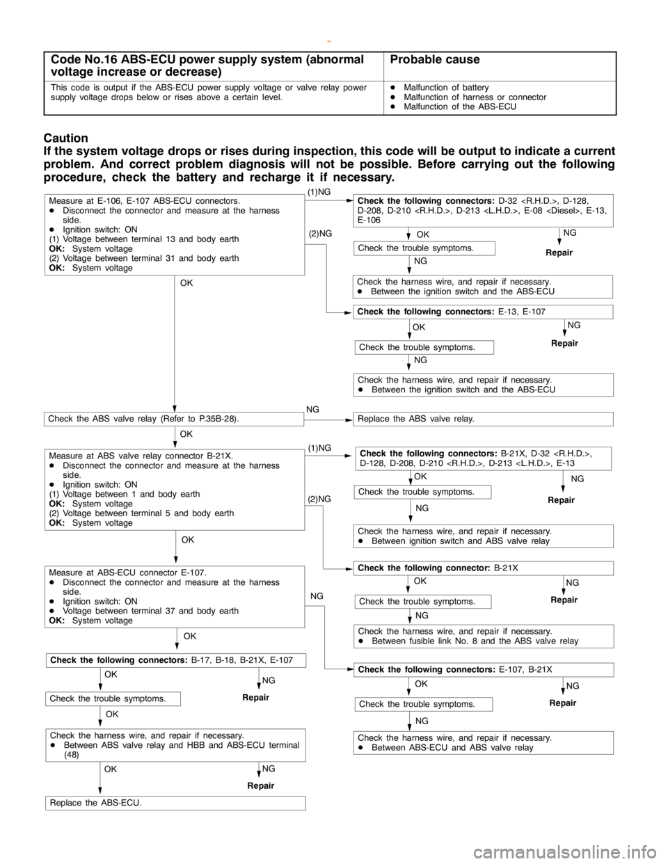
Code No.16 ABS-ECU power supply system (abnormal
voltage increase or decrease)Probable cause
This code is output if the ABS-ECU power supply voltage or valve relay power
supply voltage drops below or rises above a certain level.DMalfunction of battery
DMalfunction of harness or connector
DMalfunction of the ABS-ECU
Caution
If the system voltage drops or rises during inspection, this code will beoutput to indicate a current
problem. And correct problem diagnosis will not be possible. Before carrying out the following
procedure, check the battery and recharge it if necessary.
OKNG
Repair
OK
(1)NGCheck the following connectors:D-32
D-208, D-210
E-106
NG
Check the harness wire, and repair if necessary.
DBetween the ignition switch and the ABS-ECU (2)NG
OK
Check the trouble symptoms.
NG
Repair
NG
Check the harness wire, and repair if necessary.
DBetween the ignition switch and the ABS-ECU
Check the following connectors:E-13, E-107
Measure at E-106, E-107 ABS-ECU connectors.
DDisconnect the connector and measure at the harness
side.
DIgnition switch: ON
(1) Voltage between terminal 13 and body earth
OK:System voltage
(2) Voltage between terminal 31 and body earth
OK:System voltage
NG (1)NG
Check the ABS valve relay (Refer to P.35B-28).NGReplace the ABS valve relay.
OK
Check the harness wire, and repair if necessary.
DBetween ignition switch and ABS valve relay
OK
Repair
OK
Replace the ABS-ECU.
Check the trouble symptoms.
Check the following connectors:B-21X, D-32
D-128, D-208, D-210
NG(2)NG
Check the harness wire, and repair if necessary.
DBetween fusible link No. 8 and the ABS valve relay
OK
NG
Repair
NGCheck the trouble symptoms.
Check the following connector:B-21X
OK
NG
OK
NG
Repair
Check the harness wire, and repair if necessary.
DBetween ABS-ECU and ABS valve relayNG
Check the trouble symptoms.
Check the following connectors:E-107, B-21X
OK
OK
NG
RepairCheck the trouble symptoms.
Check the following connectors:B-17, B-18, B-21X, E-107
NG
Repair
Check the harness wire, and repair if necessary.
DBetween ABS valve relay and HBB and ABS-ECU terminal
(48)
Measure at ABS-ECU connector E-107.
DDisconnect the connector and measure at the harness
side.
DIgnition switch: ON
DVoltage between terminal 37 and body earth
OK:System voltage
Measure at ABS valve relay connector B-21X.
DDisconnect the connector and measure at the harness
side.
DIgnition switch: ON
(1) Voltage between 1 and body earth
OK:System voltage
(2) Voltage between terminal 5 and body earth
OK:System voltage
Check the trouble symptoms.
www.WorkshopManuals.co.uk
Purchased from www.WorkshopManuals.co.uk
Page 1278 of 1839
ABS <4WD> -Troubleshooting35B-15
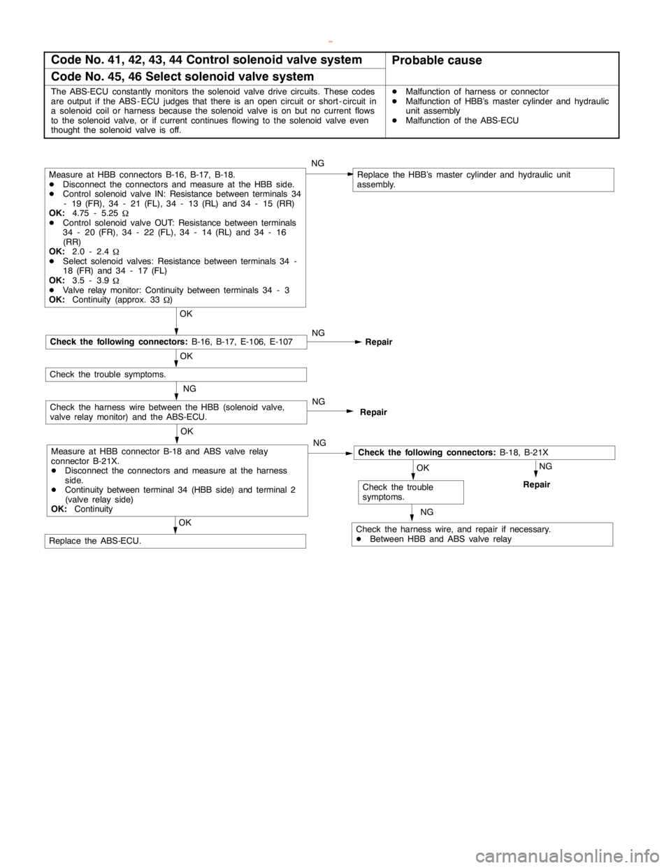
Code No. 41, 42, 43, 44 Control solenoid valve systemProbable cause
Code No. 45, 46 Select solenoid valve system
The ABS-ECU constantly monitors the solenoid valve drive circuits. These codes
are output if the ABS - ECU judges that there is an opencircuit or short - circuit in
a solenoid coil or harness because the solenoid valve is on but no current flows
to the solenoid valve, or if current continues flowing to the solenoid valve even
thought the solenoid valve is off.DMalfunction of harness or connector
DMalfunction of HBB’s master cylinder and hydraulic
unit assembly
DMalfunction of the ABS-ECU
NG
NG
OK
Repair
NG
Replace the HBB’s master cylinder and hydraulic unit
assembly.
OK
Check the following connectors:B-18, B-21X
Check the harness wire, and repair if necessary.
DBetween HBB and ABS valve relay
OK
Check the trouble
symptoms.
NG
Repair
OK
OK
Replace the ABS-ECU.
Repair
Measure at HBB connectors B-16, B-17, B-18.
DDisconnect the connectors and measure at the HBB side.
DControl solenoid valve IN: Resistance between terminals 34
- 19 (FR), 34 - 21 (FL), 34 - 13 (RL) and 34 - 15 (RR)
OK:4.75 - 5.25
W
DControl solenoid valve OUT: Resistance between terminals
34 - 20 (FR), 34 - 22 (FL), 34 - 14 (RL) and 34 - 16
(RR)
OK:2.0 - 2.4
W
DSelect solenoid valves: Resistance between terminals 34 -
18 (FR) and 34 - 17 (FL)
OK:3.5 - 3.9
W
DValve relay monitor: Continuity between terminals 34 - 3
OK:Continuity (approx. 33
W)
NG
Check the following connectors:B-16, B-17, E-106, E-107
Check the trouble symptoms.
NG
Check the harness wire between the HBB (solenoid valve,
valve relay monitor) and the ABS-ECU.
Measure at HBB connector B-18 and ABS valve relay
connector B-21X.
DDisconnect the connectors and measure at the harness
side.
DContinuity between terminal 34 (HBB side) and terminal 2
(valve relay side)
OK:ContinuityNG
www.WorkshopManuals.co.uk
Purchased from www.WorkshopManuals.co.uk
Page 1279 of 1839
ABS <4WD> -Troubleshooting35B-16
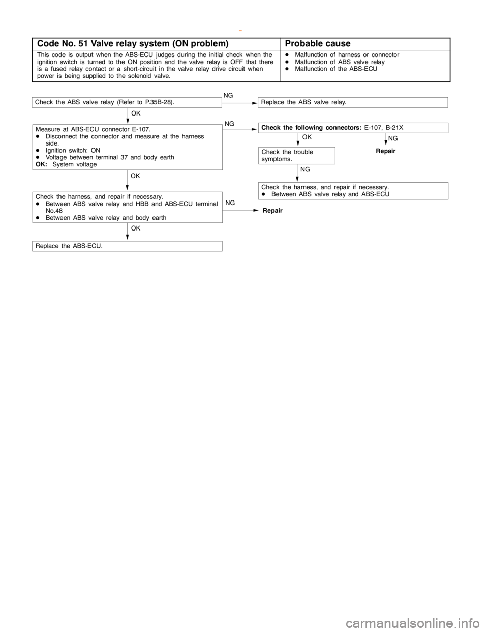
Code No. 51 Valve relay system (ON problem)Probable cause
This code is output when the ABS-ECU judges during the initial check when the
ignition switch is turned to the ON position and the valve relay is OFF that there
is a fused relay contact or a short-circuit in the valve relay drive circuit when
power isbeing supplied to the solenoidvalve.DMalfunction of harness or connector
DMalfunction of ABS valve relay
DMalfunction of the ABS-ECU
Repair NG
Check the ABS valve relay (Refer to P.35B-28).NGReplace the ABS valve relay.
OK
Check the harness, and repair if necessary.
DBetween ABS valve relay and ABS-ECU
OKNG
Repair
OK
Replace the ABS-ECU.
Check the trouble
symptoms.
Check the following connectors:E-107, B-21X OK
NG
NG
Check the harness, and repair if necessary.
DBetween ABS valve relay and HBB and ABS-ECU terminal
No.48
DBetween ABS valve relay and body earth
Measure at ABS-ECU connector E-107.
DDisconnect the connector and measure at the harness
side.
DIgnition switch: ON
DVoltage between terminal 37 and body earth
OK:System voltage
www.WorkshopManuals.co.uk
Purchased from www.WorkshopManuals.co.uk
Page 1280 of 1839
ABS <4WD> -Troubleshooting35B-17
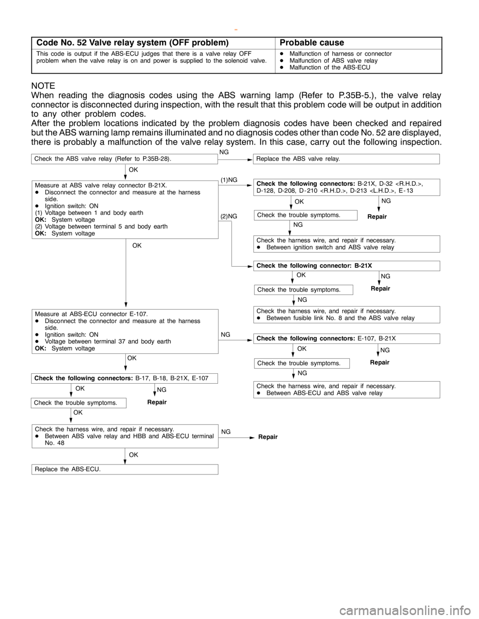
Code No. 52 Valve relay system (OFF problem)Probable cause
This code is output if the ABS-ECU judges that there is a valve relay OFF
problem when the valve relay is on and power is supplied to the solenoid valve.DMalfunction of harness or connector
DMalfunction of ABS valve relay
DMalfunction of the ABS-ECU
NOTE
When reading the diagnosis codes using the ABS warning lamp (Refer to P.35B-5.), the valve relay
connector is disconnected during inspection, with the result that this problem code will be output in addition
to any other problem codes.
After the problem locations indicated by the problem diagnosis codes have been checked and repaired
but the ABS warning lamp remains illuminated and no diagnosis codes other than code No. 52 are displayed,
there is probably a malfunction of the valve relay system. In this case, carry out the following inspection.
NG
Repair (1)NG
Check the ABS valve relay (Refer to P.35B-28).NGReplace the ABS valve relay.
OK
Check the harness wire, and repair if necessary.
DBetween ignition switch and ABS valve relay
OK
Repair
OK
Replace the ABS-ECU.
Check the trouble symptoms.
Check the following connectors:B-21X, D-32
D-128, D-208, D - 210
NG
NG
Check the harness wire, and repair if necessary.
DBetween ABS valve relay and HBB and ABS-ECU terminal
No. 48
(2)NG
Measure at ABS valve relay connector B-21X.
DDisconnect the connector and measure at the harness
side.
DIgnition switch: ON
(1) Voltage between 1 and body earth
OK:System voltage
(2) Voltage between terminal 5 and body earth
OK:System voltage
Check the harness wire, and repair if necessary.
DBetween fusible link No. 8 and the ABS valve relay
OK
NG
Repair
NGCheck the trouble symptoms.
Check the following connector: B-21X
OK
NG
Measure at ABS-ECU connector E-107.
DDisconnect the connector and measure at the harness
side.
DIgnition switch: ON
DVoltage between terminal 37 and body earth
OK:System voltage
OK
NG
Repair
Check the harness wire, and repair if necessary.
DBetween ABS-ECU and ABS valve relayNG
Check the trouble symptoms.
Check the following connectors:E-107, B-21X
OK
OK
NG
RepairCheck the trouble symptoms.
Check the following connectors:B-17, B-18, B-21X, E-107
www.WorkshopManuals.co.uk
Purchased from www.WorkshopManuals.co.uk
Page 1283 of 1839
ABS <4WD> -Troubleshooting35B-20
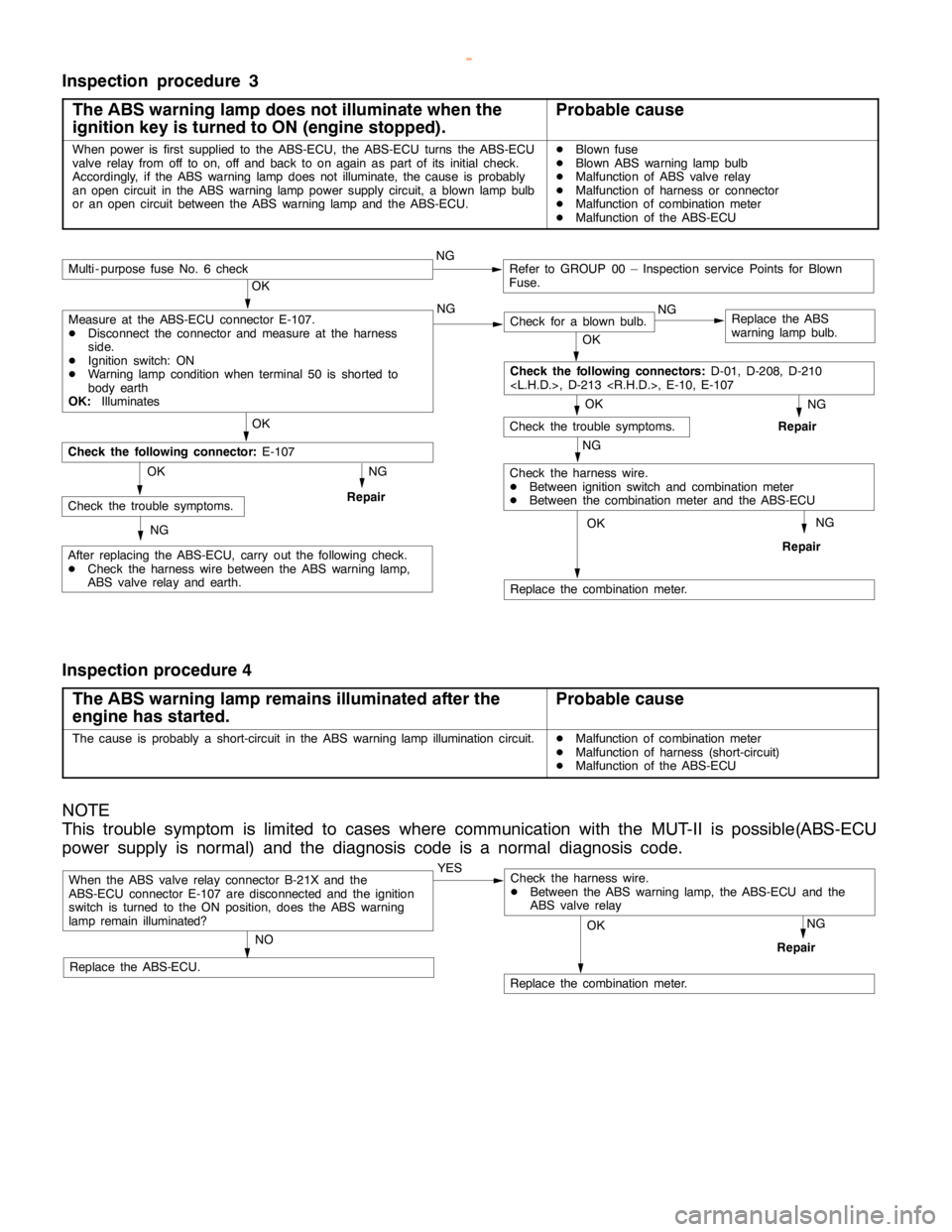
Inspection procedure 3
The ABS warning lamp does not illuminate when the
ignition key is turned to ON (engine stopped).
Probable cause
When power is first supplied to the ABS-ECU, the ABS-ECU turns the ABS-ECU
valve relay from off to on, off and back to onagain aspart of its initial check.
Accordingly, if the ABS warninglampdoes not illuminate, the cause is probably
an opencircuit in the ABS warninglamppower supply circuit, a blownlamp bulb
or an opencircuit between the ABS warninglamp and theABS-ECU.DBlown fuse
DBlown ABS warninglamp bulb
DMalfunction of ABS valve relay
DMalfunction of harness or connector
DMalfunction of combination meter
DMalfunction of the ABS-ECU
NG
Replace the combination meter.
NG
Repair
OK
NG
Check for a blown bulb.Replace the ABS
warning lamp bulb.
OK
NG
Repair
OK
Check the trouble symptoms.
Multi - purpose fuse No. 6 checkNGRefer to GROUP 00 – Inspection service Points for Blown
Fuse.
NG
Check the harness wire.
DBetween ignition switch and combination meter
DBetween the combination meter and the ABS-ECU
OK
OK
After replacing the ABS-ECU, carry out the following check.
DCheck the harness wire between the ABS warning lamp,
ABS valve relay and earth.
Check the following connector:E-107
NG
RepairCheck the trouble symptoms.OK
NG
Check the following connectors:D-01, D-208, D-210
Measure at the ABS-ECU connector E-107.
DDisconnect the connector and measure at the harness
side.
DIgnition switch: ON
DWarning lamp conditionwhen terminal 50 is shorted to
body earth
OK:Illuminates
Inspection procedure 4
The ABS warning lamp remains illuminated after the
engine has started.
Probable cause
The cause is probably a short-circuit in the ABS warninglamp illuminationcircuit.DMalfunction of combination meter
DMalfunction of harness (short-circuit)
DMalfunction of the ABS-ECU
NOTE
This trouble symptom is limited to cases where communication with the MUT-II is possible(ABS-ECU
power supply is normal) and the diagnosis code is a normal diagnosis code.
When the ABS valve relay connector B-21X and the
ABS-ECU connector E-107 are disconnected and the ignition
switch is turned to the ON position, does the ABS warning
lamp remain illuminated?YES
NO
Replace the ABS-ECU.
Replace the combination meter.
NG
Repair
OK
Check the harness wire.
DBetween the ABS warning lamp, the ABS-ECU and the
ABS valve relay
www.WorkshopManuals.co.uk
Purchased from www.WorkshopManuals.co.uk
Page 1288 of 1839

ABS <4WD> -Troubleshooting35B-25
Termi-
nal
No.Normal condition Inspection conditions Check item
37ABS valve relay outputIgnition
switch: ONWhen system abnormality is
detected and relay is offSystem voltage
When relay is on approx. 1
second after engine starts2 V or less
39Brake warning lamp outputIgnitionWhen lamp is switched off2 V or less
switch: ONWhen lamp is illuminatedSystem voltage
40Control solenoid valve OUT (RL)Ignition switch: ONSystem voltage
41Control solenoid valve OUT(FR)Ignition switch: ONSystem voltage
46Center differential lock switch
input
switch: ONTransfer selector lever position:
2H, 4HSystem voltage
Transfer selector lever position:
4HLc, 4LLc2 V or less
4WD detection switch input
switch: ONTransfer selector lever position:
2HSystem voltage
Transfer selector lever position:
4H2 V or less
47Diagnosis select inputWhen the MUT-IIis connected1 V or less
When the MUT-IIis not connectedApprox. 12 V
48Valve relay monitorIgnition switch: ONSystem voltage
50ABS warning lamp outputIgnitionWhen lamp is switched offSystem voltage
switch: ONWhen lamp is illuminated2 V or less
51Control solenoid valve IN (RL)Ignition switch: ONSystem voltage
52Control solenoid valve IN (FR)Ignition switch: ONSystem voltage
www.WorkshopManuals.co.uk
Purchased from www.WorkshopManuals.co.uk
Page 1573 of 1839

54A-3
ON-VEHICLE SERVICE 46......................
Room Lamp Delay-off Time Adjustment
Procedure 46...............................
REAR COMBINATION LAMP 47...........
SPECIAL TOOLS 47...........................
TROUBLESHOOTING 47.......................
REAR COMBINATION LAMP 47................
HIGH-MOUNTED STOP LAMP 48.........
COLUMN SWITCH 48....................
SPECIAL TOOLS 48...........................
COLUMN SWITCH 48..........................
HAZARD WARNING LAMP SWITCH 50....
SPECIAL TOOLS 50...........................
HAZARD WARNING LAMP SWITCH 50.........
HORN 51................................
CIGARETTE LIGHTER 51.................
ACCESSORY SOCKET 51................
RHEOSTAT 52...........................
CLOCK OR CENTER DISPLAY 53........
TROUBLESHOOTING 53.......................
CLOCK OR CENTER DISPLAY 67..............
RADIO/TAPE PLAYER 68.................
TROUBLESHOOTING 68.......................
RADIO AND CD AUTO CHANGER 81..........
FRONT SPEAKERS 82...................
REAR SPEAKERS 82.....................
ANTENNA83 ............................DEFOGGER 86...........................
TROUBLESHOOTING
ON-VEHICLE SERVICE 86.....................
Printed Heater Check 86.....................
Defogger Relay Continuity Check 86...........
DEFOGGER SWITCH 87.......................
SMART WIRING SYSTEM (SWS)
Refer to GROUP 54B ....................
RADIATOR (RADIATOR FAN MOTOR)
Refer to GROUP 14 ......................
AUTOMATIC TRANSMISSION
Refer to GROUP 23 ......................
ANTI-LOCK BRAKE SYSTEM (ABS)
Refer to GROUP 35B ....................
DOOR HANDLE LATCH (DOOR LOCK)
Refer to GROUP 42 ......................
DOOR GLASS-REGULATOR (POWER
WINDOWS)
Refer to GROUP 42 ......................
KEYLESS ENTRY SYSTEM
Refer to GROUP 42 ......................
WINDSHIELD WIPER/WASHER
Refer to GROUP 51 ......................
REAR WIPER/WASHER
Refer to GROUP 51 ......................
SRS AIRBAG Refer to GROUP 52B......
HEATER Refer to GROUP 55.............
AIR CONDITIONER Refer to GROUP 55...
www.WorkshopManuals.co.uk
Purchased from www.WorkshopManuals.co.uk
Page 1644 of 1839
CHASSIS ELECTRICAL -Radio/Tape Player54A-74
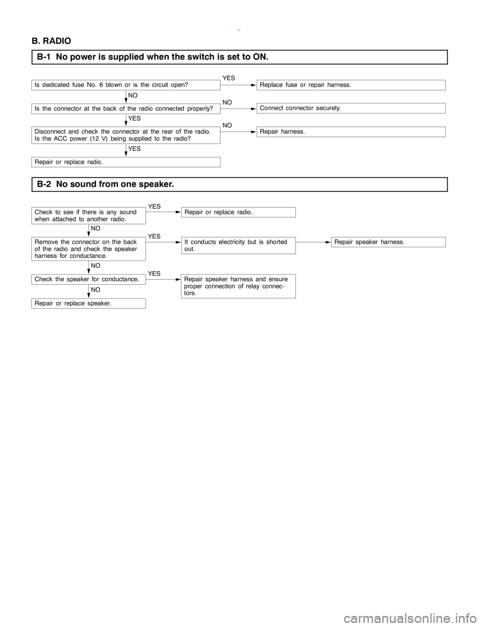
B. RADIO
B-1 No power is supplied when the switch is set to ON.
Is dedicated fuse No. 6 blown or is the circuitopen?YESReplace fuse or repair harness.
NO
Is the connector at the back of the radio connected properly?NOConnect connector securely.
YES
Disconnect and check the connector at the rear of the radio.
Is the ACC power (12 V)being supplied to the radio?NORepair harness.
YES
Repair or replace radio.
B-2 No sound from one speaker.
Check to see if there is any sound
when attached to another radio.YESRepair or replace radio.
NO
Remove the connector on the back
of the radio and check the speaker
harness for conductance.YESIt conducts electricity but is shorted
out.Repair speaker harness.
NO
Check the speaker for conductance.YESRepair speaker harness and ensure
proper connection of relay connec-
tors.
NO
Repair or replace speaker.
www.WorkshopManuals.co.uk
Purchased from www.WorkshopManuals.co.uk