2000 DODGE NEON check oil
[x] Cancel search: check oilPage 831 of 1285
(3) Squeeze retainer tabs together and pull fuel
tube/quick-connect fitting assembly off of fuel tube
nipple. The retainer will remain on fuel tube.
INSTALLATION
CAUTION: Never install a quick-connect fitting
without the retainer being either on the fuel tube or
already in the quick-connect fitting. In either case,
ensure the retainer locks securely into the quick-
connect fitting by firmly pulling on fuel tube and fit-
ting to ensure it is secured.
(1) Using a clean lint free cloth, clean the fuel tube
nipple and retainer.
(2) Prior to connecting the fitting to the fuel tube,
coat the fuel tube nipple with clean 30 weight engine
oil.
(3) Push the quick-connect fitting over the fuel
tube until theretainer seats and a click is heard.
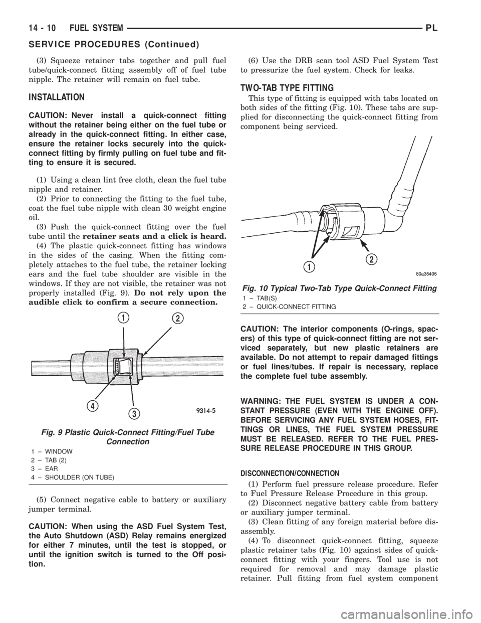
(4) The plastic quick-connect fitting has windows
in the sides of the casing. When the fitting com-
pletely attaches to the fuel tube, the retainer locking
ears and the fuel tube shoulder are visible in the
windows. If they are not visible, the retainer was not
properly installed (Fig. 9).Do not rely upon the
audible click to confirm a secure connection.
(5) Connect negative cable to battery or auxiliary
jumper terminal.
CAUTION: When using the ASD Fuel System Test,
the Auto Shutdown (ASD) Relay remains energized
for either 7 minutes, until the test is stopped, or
until the ignition switch is turned to the Off posi-
tion.(6) Use the DRB scan tool ASD Fuel System Test
to pressurize the fuel system. Check for leaks.
TWO-TAB TYPE FITTING
This type of fitting is equipped with tabs located on
both sides of the fitting (Fig. 10). These tabs are sup-
plied for disconnecting the quick-connect fitting from
component being serviced.
CAUTION: The interior components (O-rings, spac-
ers) of this type of quick-connect fitting are not ser-
viced separately, but new plastic retainers are
available. Do not attempt to repair damaged fittings
or fuel lines/tubes. If repair is necessary, replace
the complete fuel tube assembly.
WARNING:
THE FUEL SYSTEM IS UNDER A CON-
STANT PRESSURE (EVEN WITH THE ENGINE OFF).
BEFORE SERVICING ANY FUEL SYSTEM HOSES, FIT-
TINGS OR LINES, THE FUEL SYSTEM PRESSURE
MUST BE RELEASED. REFER TO THE FUEL PRES-
SURE RELEASE PROCEDURE IN THIS GROUP.
DISCONNECTION/CONNECTION
(1) Perform fuel pressure release procedure. Refer
to Fuel Pressure Release Procedure in this group.
(2) Disconnect negative battery cable from battery
or auxiliary jumper terminal.
(3) Clean fitting of any foreign material before dis-
assembly.
(4) To disconnect quick-connect fitting, squeeze
plastic retainer tabs (Fig. 10) against sides of quick-
connect fitting with your fingers. Tool use is not
required for removal and may damage plastic
retainer. Pull fitting from fuel system component
Fig. 9 Plastic Quick-Connect Fitting/Fuel Tube
Connection
1 ± WINDOW
2 ± TAB (2)
3 ± EAR
4 ± SHOULDER (ON TUBE)
Fig. 10 Typical Two-Tab Type Quick-Connect Fitting
1 ± TAB(S)
2 ± QUICK-CONNECT FITTING
14 - 10 FUEL SYSTEMPL
SERVICE PROCEDURES (Continued)
Page 832 of 1285
being serviced. The plastic retainer will remain on
component being serviced after fitting is discon-
nected. The O-rings and spacer will remain in quick-
connect fitting connector body.
(5) Inspect quick-connect fitting body and compo-
nent for damage. Replace as necessary.
CAUTION:
When the quick-connect fitting was dis-
connected, the plastic retainer will remain on the com-
ponent being serviced. If this retainer must be
removed, very carefully release the retainer from the
component with two small screwdrivers. After removal,
inspect the retainer for cracks or any damage.
(6) Prior to connecting quick-connect fitting to
component being serviced, check condition of fitting
and component. Clean parts with a lint-free cloth.
Lubricate with clean engine oil.
(7) Insert quick-connect fitting to component being
serviced and into plastic retainer. When a connection
is made, a click will be heard.
(8) Verify a locked condition by firmly pulling on
fuel tube and fitting (15-30 lbs.).
(9) Connect negative cable to battery or auxiliary
jumper terminal.
(10) Start engine and check for leaks.
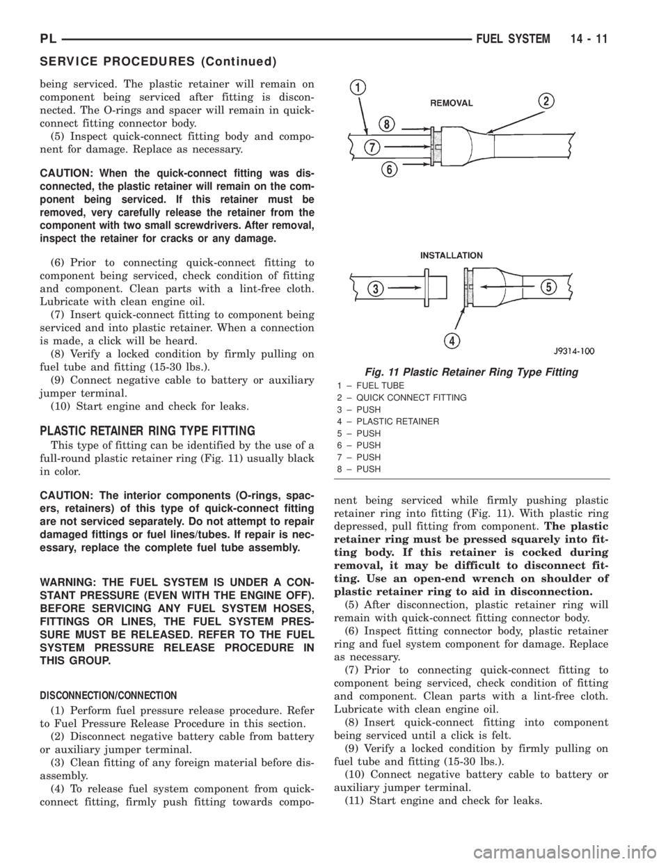
PLASTIC RETAINER RING TYPE FITTING
This type of fitting can be identified by the use of a
full-round plastic retainer ring (Fig. 11) usually black
in color.
CAUTION: The interior components (O-rings, spac-
ers, retainers) of this type of quick-connect fitting
are not serviced separately. Do not attempt to repair
damaged fittings or fuel lines/tubes. If repair is nec-
essary, replace the complete fuel tube assembly.
WARNING: THE FUEL SYSTEM IS UNDER A CON-
STANT PRESSURE (EVEN WITH THE ENGINE OFF).
BEFORE SERVICING ANY FUEL SYSTEM HOSES,
FITTINGS OR LINES, THE FUEL SYSTEM PRES-
SURE MUST BE RELEASED. REFER TO THE FUEL
SYSTEM PRESSURE RELEASE PROCEDURE IN
THIS GROUP.
DISCONNECTION/CONNECTION
(1) Perform fuel pressure release procedure. Refer
to Fuel Pressure Release Procedure in this section.
(2) Disconnect negative battery cable from battery
or auxiliary jumper terminal.
(3) Clean fitting of any foreign material before dis-
assembly.
(4) To release fuel system component from quick-
connect fitting, firmly push fitting towards compo-nent being serviced while firmly pushing plastic
retainer ring into fitting (Fig. 11). With plastic ring
depressed, pull fitting from component.The plastic
retainer ring must be pressed squarely into fit-
ting body. If this retainer is cocked during
removal, it may be difficult to disconnect fit-
ting. Use an open-end wrench on shoulder of
plastic retainer ring to aid in disconnection.
(5) After disconnection, plastic retainer ring will
remain with quick-connect fitting connector body.
(6) Inspect fitting connector body, plastic retainer
ring and fuel system component for damage. Replace
as necessary.
(7) Prior to connecting quick-connect fitting to
component being serviced, check condition of fitting
and component. Clean parts with a lint-free cloth.
Lubricate with clean engine oil.
(8) Insert quick-connect fitting into component
being serviced until a click is felt.
(9) Verify a locked condition by firmly pulling on
fuel tube and fitting (15-30 lbs.).
(10) Connect negative battery cable to battery or
auxiliary jumper terminal.
(11) Start engine and check for leaks.
Fig. 11 Plastic Retainer Ring Type Fitting
1 ± FUEL TUBE
2 ± QUICK CONNECT FITTING
3 ± PUSH
4 ± PLASTIC RETAINER
5 ± PUSH
6 ± PUSH
7 ± PUSH
8 ± PUSH
PLFUEL SYSTEM 14 - 11
SERVICE PROCEDURES (Continued)
Page 834 of 1285
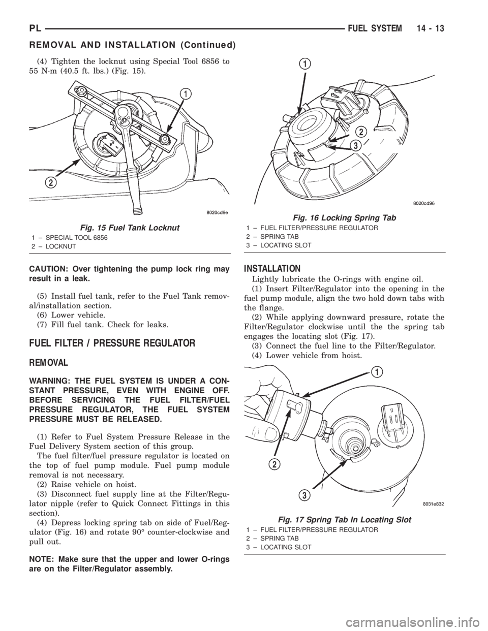
(4) Tighten the locknut using Special Tool 6856 to
55 N´m (40.5 ft. lbs.) (Fig. 15).
CAUTION: Over tightening the pump lock ring may
result in a leak.
(5) Install fuel tank, refer to the Fuel Tank remov-
al/installation section.
(6) Lower vehicle.
(7) Fill fuel tank. Check for leaks.
FUEL FILTER / PRESSURE REGULATOR
REMOVAL
WARNING: THE FUEL SYSTEM IS UNDER A CON-
STANT PRESSURE, EVEN WITH ENGINE OFF.
BEFORE SERVICING THE FUEL FILTER/FUEL
PRESSURE REGULATOR, THE FUEL SYSTEM
PRESSURE MUST BE RELEASED.
(1) Refer to Fuel System Pressure Release in the
Fuel Delivery System section of this group.
The fuel filter/fuel pressure regulator is located on
the top of fuel pump module. Fuel pump module
removal is not necessary.
(2) Raise vehicle on hoist.
(3) Disconnect fuel supply line at the Filter/Regu-
lator nipple (refer to Quick Connect Fittings in this
section).
(4) Depress locking spring tab on side of Fuel/Reg-
ulator (Fig. 16) and rotate 90É counter-clockwise and
pull out.
NOTE: Make sure that the upper and lower O-rings
are on the Filter/Regulator assembly.
INSTALLATION
Lightly lubricate the O-rings with engine oil.
(1) Insert Filter/Regulator into the opening in the
fuel pump module, align the two hold down tabs with
the flange.
(2) While applying downward pressure, rotate the
Filter/Regulator clockwise until the the spring tab
engages the locating slot (Fig. 17).
(3) Connect the fuel line to the Filter/Regulator.
(4) Lower vehicle from hoist.
Fig. 15 Fuel Tank Locknut
1 ± SPECIAL TOOL 6856
2 ± LOCKNUT
Fig. 16 Locking Spring Tab
1 ± FUEL FILTER/PRESSURE REGULATOR
2 ± SPRING TAB
3 ± LOCATING SLOT
Fig. 17 Spring Tab In Locating Slot
1 ± FUEL FILTER/PRESSURE REGULATOR
2 ± SPRING TAB
3 ± LOCATING SLOT
PLFUEL SYSTEM 14 - 13
REMOVAL AND INSTALLATION (Continued)
Page 842 of 1285
FUEL INJECTION SYSTEM
TABLE OF CONTENTS
page page
DESCRIPTION AND OPERATION
INJECTION SYSTEM......................22
MODES OF OPERATION...................22
SYSTEM DIAGNOSIS......................24
POWER DISTRIBUTION CENTER............24
POWERTRAIN CONTROL MODULE...........24
PCM GROUND...........................26
5 VOLT SUPPLYÐPCM OUTPUT.............26
8-VOLT SUPPLYÐPCM OUTPUT.............26
FUEL CORRECTION or ADAPTIVE MEMORIES . . 26
PROGRAMMABLE COMMUNICATIONS
INTERFACE (PCI) BUS...................27
AIR CONDITIONING PRESSURE
TRANSDUCERÐPCM INPUT..............27
AUTOMATIC SHUTDOWN (ASD) SENSEÐ
PCM INPUT...........................27
BATTERY VOLTAGEÐPCM INPUT............28
BRAKE SWITCHÐPCM INPUT...............28
CAMSHAFT POSITION SENSORÐPCM INPUT . . 28
CLUTCH INTERLOCK/UPSTOP SWITCH.......29
CRANKSHAFT POSITION SENSORÐPCM
INPUT................................30
ENGINE COOLANT TEMPERATURE
SENSORÐPCM INPUT...................30
FUEL LEVEL SENSORÐPCM INPUT..........31
HEATED OXYGEN SENSOR (O2 SENSOR)Ð
PCM INPUT...........................32
IGNITION CIRCUIT SENSEÐPCM INPUT......34
INLET AIR TEMPERATURE SENSORÐPCM
INPUT................................34
KNOCK SENSORÐPCM INPUT..............34
MANIFOLD ABSOLUTE PRESSURE (MAP)
SENSORÐPCM INPUT...................35
POWER STEERING PRESSURE SWITCHÐ
PCM INPUT...........................35
SENSOR RETURNÐPCM INPUT.............35
SPEED CONTROLÐPCM INPUT.............36
SCI RECEIVEÐPCM INPUT.................36
PARK/NEUTRAL POSITION SWITCHÐPCM
INPUT................................36
THROTTLE POSITION SENSORÐPCM INPUT . . 36VEHICLE SPEED SIGNAL (VSS)ÐPCM INPUT . . 37
AIR CONDITIONING CLUTCH RELAYÐPCM
OUTPUT..............................38
AUTOMATIC SHUTDOWN RELAYÐPCM
OUTPUT..............................38
CHARGING SYSTEM INDICATOR LAMPÐPCM
OUTPUT..............................38
FUEL PUMP RELAYÐPCM OUTPUT..........38
PROPORTIONAL PURGE SOLENOIDÐPCM
OUTPUT..............................39
GENERATOR FIELDÐPCM OUTPUT..........39
IDLE AIR CONTROL MOTORÐPCM OUTPUT . . . 39
DATA LINK CONNECTOR...................40
FUEL INJECTORSÐPCM OUTPUT...........40
IGNITION COILÐPCM OUTPUT..............40
MALFUNCTION INDICATOR (CHECK ENGINE)
LAMPÐPCM OUTPUT...................41
SPEED CONTROLÐPCM INPUT.............41
SCI RECEIVEÐPCM OUTPUT...............41
TACHOMETERÐPCM OUTPUT..............42
TORQUE CONVERTOR CLUTCH SOLENOIDÐ
PCM OUTPUT..........................42
REMOVAL AND INSTALLATION
THROTTLE BODY........................42
THROTTLE POSITION SENSOR.............43
IDLE AIR CONTROL MOTOR................43
MAP SENSOR...........................44
POWERTRAIN CONTROL MODULE (PCM).....44
UPSTREAM HEATED OXYGEN SENSOR......45
DOWNSTREAM HEATED OXYGEN SENSOR
1/2 ..................................46
AIR CLEANER BOX.......................46
AIR CLEANER ELEMENT...................47
ENGINE COOLANT TEMPERATURE SENSOR . . . 47
VEHICLE SPEED SENSOR.................47
KNOCK SENSOR.........................48
SPECIFICATIONS
VECI LABEL.............................49
TORQUE...............................49
SPECIAL TOOLS
FUEL..................................49
PLFUEL SYSTEM 14 - 21
Page 844 of 1285
1 second. Therefore, battery voltage is not supplied to
the fuel pump, ignition coil, fuel injectors and heated
oxygen sensors.
ENGINE START-UP MODE
This is an OPEN LOOP mode. If the vehicle is in
park or neutral (automatic transaxles) or the clutch
pedal is depressed (manual transaxles) the ignition
switch energizes the starter relay. The following
actions occur when the starter motor is engaged.
²If the PCM receives the camshaft position sensor
and crankshaft position sensor signals, it energizes
the Auto Shutdown (ASD) relay and fuel pump relay.
If the PCM does not receive both signals within
approximately one second, it will not energize the
ASD relay and fuel pump relay. The ASD and fuel
pump relays supply battery voltage to the fuel pump,
fuel injectors, ignition coil and heated oxygen sen-
sors.
²The PCM energizes the injectors (on the 69É
degree falling edge) for a calculated pulse width until
it determines crankshaft position from the camshaft
position sensor and crankshaft position sensor sig-
nals. The PCM determines crankshaft position within
1 engine revolution.
²After determining crankshaft position, the PCM
begins energizing the injectors in sequence. It adjusts
injector pulse width and controls injector synchroni-
zation by turning the individual ground paths to the
injectors On and Off.
²When the engine idles within664 RPM of its
target RPM, the PCM compares current MAP sensor
value with the atmospheric pressure value received
during the Ignition Switch On (zero RPM) mode. If
the PCM does not detect a minimum difference
between the two values, it sets a MAP diagnostic
trouble code into memory.
Once the ASD and fuel pump relays have been
energized, the PCM determines injector pulse width
based on the following:
²Battery voltage
²Engine coolant temperature
²Engine RPM
²Intake air temperature (IAT)
²Throttle position
²The number of engine revolutions since cranking
was initiated.
During Start-up the PCM maintains ignition tim-
ing at 9É BTDC.
ENGINE WARM-UP MODE
This is an OPEN LOOP mode. The following inputs
are received by the PCM:
²Engine coolant temperature
²Manifold Absolute Pressure (MAP)
²Intake air temperature (IAT)²Crankshaft position (engine speed)
²Camshaft position
²Knock sensor
²Throttle position
²A/C switch
²Battery voltage
²Power steering pressure switch
²Vehicle speed
²Speed control
²O2 sensors
²All diagnostics
The PCM adjusts injector pulse width and controls
injector synchronization by turning the individual
ground paths to the injectors On and Off.
The PCM adjusts ignition timing and engine idle
speed. Engine idle speed is adjusted through the idle
air control motor.
CRUISE OR IDLE MODE
When the engine is at operating temperature this
is a CLOSED LOOP mode. During cruising or idle
the following inputs are received by the PCM:
²Intake air temperature
²Engine coolant temperature
²Manifold absolute pressure
²Crankshaft position (engine speed)
²Camshaft position
²Knock sensor
²Throttle position
²Exhaust gas oxygen content
²A/C control positions
²Power steering pressure switch
²Battery voltage
²Vehicle speed
The PCM adjusts injector pulse width and controls
injector synchronization by turning the individual
ground paths to the injectors On and Off.
The PCM adjusts engine idle speed and ignition
timing. The PCM adjusts the air/fuel ratio according
to the oxygen content in the exhaust gas (measured
by the upstream and downstream heated oxygen sen-
sor).
The PCM monitors for engine misfire. During
active misfire and depending on the severity, the
PCM either continuously illuminates or flashes the
malfunction indicator lamp (Check Engine light on
instrument panel). Also, the PCM stores an engine
misfire DTC in memory.
The PCM performs several diagnostic routines.
They include:
²Oxygen sensor monitor
²Downstream heated oxygen sensor diagnostics
during open loop operation (except for shorted)
²Fuel system monitor
²EGR monitor
²Purge system monitor
PLFUEL SYSTEM 14 - 23
DESCRIPTION AND OPERATION (Continued)
Page 846 of 1285
²Air Conditioning Controls
²Battery Voltage
²Inlet Air/Battery Temperature Sensor
²Brake Switch
²Camshaft Position Sensor
²Crankshaft Position Sensor
²Engine Coolant Temperature Sensor
²Fuel Level Sensor
²Ignition Switch
²Inlet Air/Intake Air Temperature Sensor
²Knock Sensor
²Manifold Absolute Pressure (MAP) Sensor
²Oxygen Sensors
²Power Steering Pressure Switch²SCI Receive
²Speed Control Switches
²Throttle Position Sensor
²Transmission Park/Neutral Switch (automatic
transmission)
²Vehicle Speed Sensor
PCM Outputs:
²Air Conditioning WOT Relay
²Auto Shutdown (ASD) Relay
²Charging Indicator Lamp
²Data Link Connector
²Proportional Purge Solenoid
²EGR Solenoid
²Fuel Injectors
²Fuel Pump Relay
²Generator Field
²Idle Air Control Motor
²Ignition Coils
²Malfunction Indicator (Check Engine) Lamp
²Radiator Fan Relay
²Speed Control Solenoids
²Tachometer
²Torque Convertor Clutch Solenoid
Based on inputs it receives, the PCM adjusts fuel
injector pulse width, idle speed, ignition spark
advance, ignition coil dwell and EVAP canister purge
operation. The PCM regulates the cooling fan, air
conditioning and speed control systems. The PCM
changes generator charge rate by adjusting the gen-
erator field. The PCM also performs diagnostics.
The PCM adjusts injector pulse width (air-fuel
ratio) based on the following inputs.
²Battery voltage
²Coolant temperature
²Inlet Air/Intake air temperature
²Exhaust gas content (oxygen sensor)
²Engine speed (crankshaft position sensor)
²Manifold absolute pressure
²Throttle position
The PCM adjusts ignition timing based on the fol-
lowing inputs.
²Coolant temperature
²Inlet Air/Intake air temperature
²Engine speed (crankshaft position sensor)
²Knock sensor
²Manifold absolute pressure
²Throttle position
²Transmission gear selection (park/neutral
switch)
The PCM also adjusts engine idle speed through
the idle air control motor based on the following
inputs.
²Air conditioning sense
²Battery voltage
²Battery temperature
²Brake switch
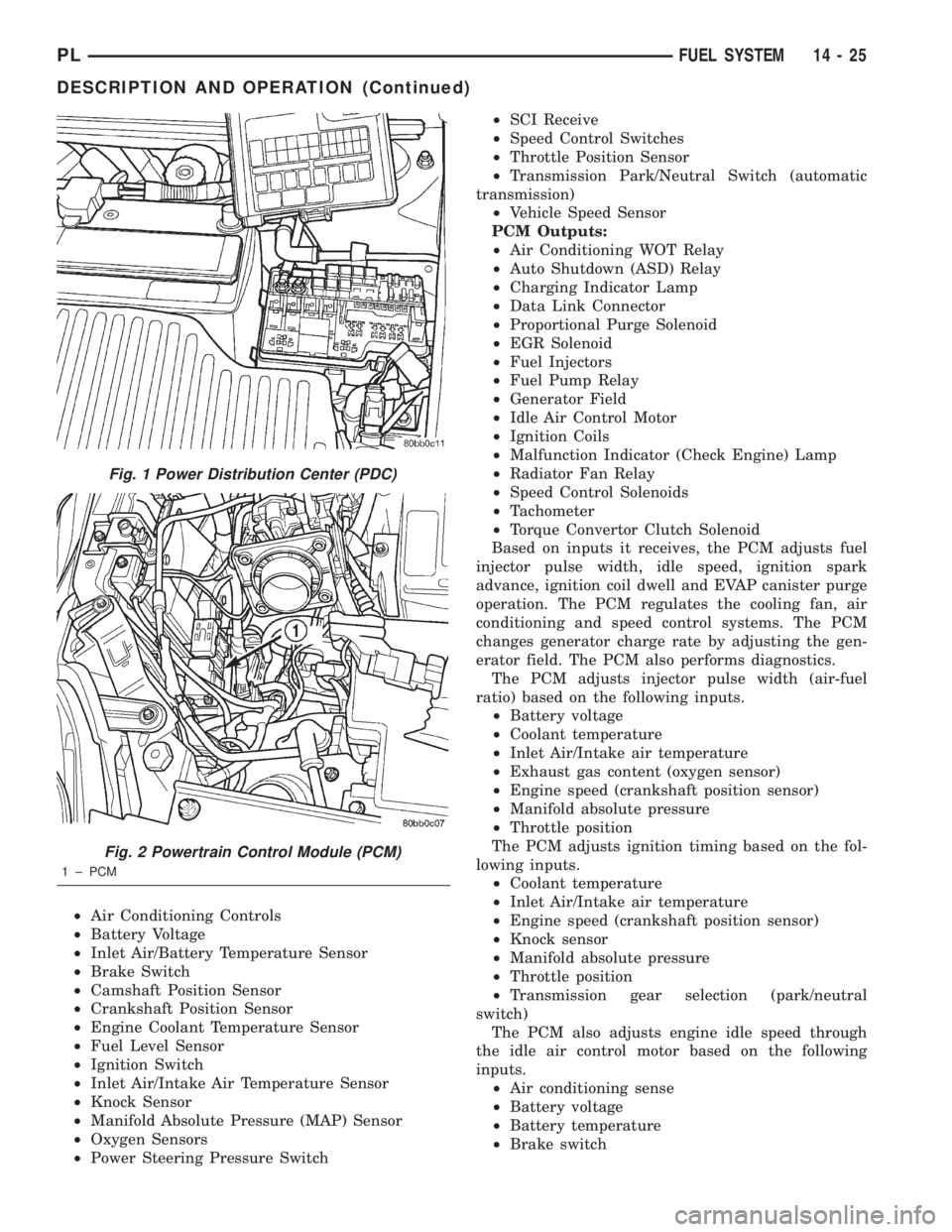
Fig. 1 Power Distribution Center (PDC)
Fig. 2 Powertrain Control Module (PCM)
1 ± PCM
PLFUEL SYSTEM 14 - 25
DESCRIPTION AND OPERATION (Continued)
Page 848 of 1285
As the engine enters one of these cells the PCM
looks at the amount of short term correction being
used. Because the goal is to keep short term at 0 (O2
Sensor switching at 0.5 volt), long term will update
in the same direction as short term correction was
moving to bring the short term back to 0. Once short
term is back at 0, this long term correction factor is
stored in memory.
The values stored in long term adaptive memory
are used for all operating conditions, including open
loop. However, the updating of the long term memoryoccurs after the engine has exceeded approximately
17É F, with fuel control in closed loop and two min-
utes of engine run time. This is done to prevent any
transitional temperature or start-up compensations
from corrupting long term fuel correction.
Long term adaptive memory can change the pulse-
width by as much as 25%, which means it can correct
for all of short term. It is possible to have a problem
that would drive long term to 25% and short term to
another 25% for a total change of 50% away from
base pulse-width calculation.
TYPICAL ADAPTIVE MEMORY FUEL CELLS
Open
ThrottleOpen
ThrottleOpen
ThrottleOpen
ThrottleOpen
ThrottleOpen
Throttle Idle Decel
Vacuum 20 17 13 9 5 0
Above 1,984
rpm1 3 5 7 9 11 13 Drive 15
Below 1,984
rpm02 4 6 8 1012
Neutral14
MAP volt =0 1.4 2.0 2.6 3.3 3.9
Fuel Correction Diagnostics
There are two fuel correction diagnostic routines:
²Fuel System Rich
²Fuel System Lean
A DTC is set and the MIL is illuminated if the
PCM detects either of these conditions.
PROGRAMMABLE COMMUNICATIONS
INTERFACE (PCI) BUS
OPERATION
Various modules exchange information through a
communications port called the PCI Bus. The Power-
train Control Module (PCM) transmits the Malfunc-
tion Indicator Lamp (Check Engine) On/Off signal
and engine RPM on the PCI Bus. The PCM receives
the Air Conditioning select input, transaxle gear
position inputs over the PCI Bus. The PCM also
receives the air conditioning evaporator temperature
signal from the PCI Bus.
The following components access or send informa-
tion on the PCI Bus.
²Instrument Panel
²Body Control Module
²Air Bag System Diagnostic Module
²Full ATC Display Head
²ABS Module
²Transmission Control Module
²Powertrain Control Module
²Overhead Travel Module
AIR CONDITIONING PRESSURE
TRANSDUCERÐPCM INPUT
OPERATION
The Powertrain Control Module (PCM) monitors
the A/C compressor discharge (high side) pressure
through the air conditioning pressure transducer.
The transducer supplies an input to the PCM. The
PCM engages the A/C compressor clutch if pressure
is sufficient for A/C system operation.
AUTOMATIC SHUTDOWN (ASD) SENSEÐPCM
INPUT
OPERATION
The ASD sense circuit informs the PCM when the
ASD relay energizes. A 12 volt signal at this input
indicates to the PCM that the ASD has been acti-
vated. This input is used only to sense that the ASD
relay is energized.
When energized, the ASD relay supplies battery
voltage to the fuel injectors, ignition coils and the
heating element in each oxygen sensor. If the PCM
does not receive 12 volts from this input after
grounding the ASD relay, it sets a Diagnostic Trouble
Code (DTC).
PLFUEL SYSTEM 14 - 27
DESCRIPTION AND OPERATION (Continued)
Page 862 of 1285
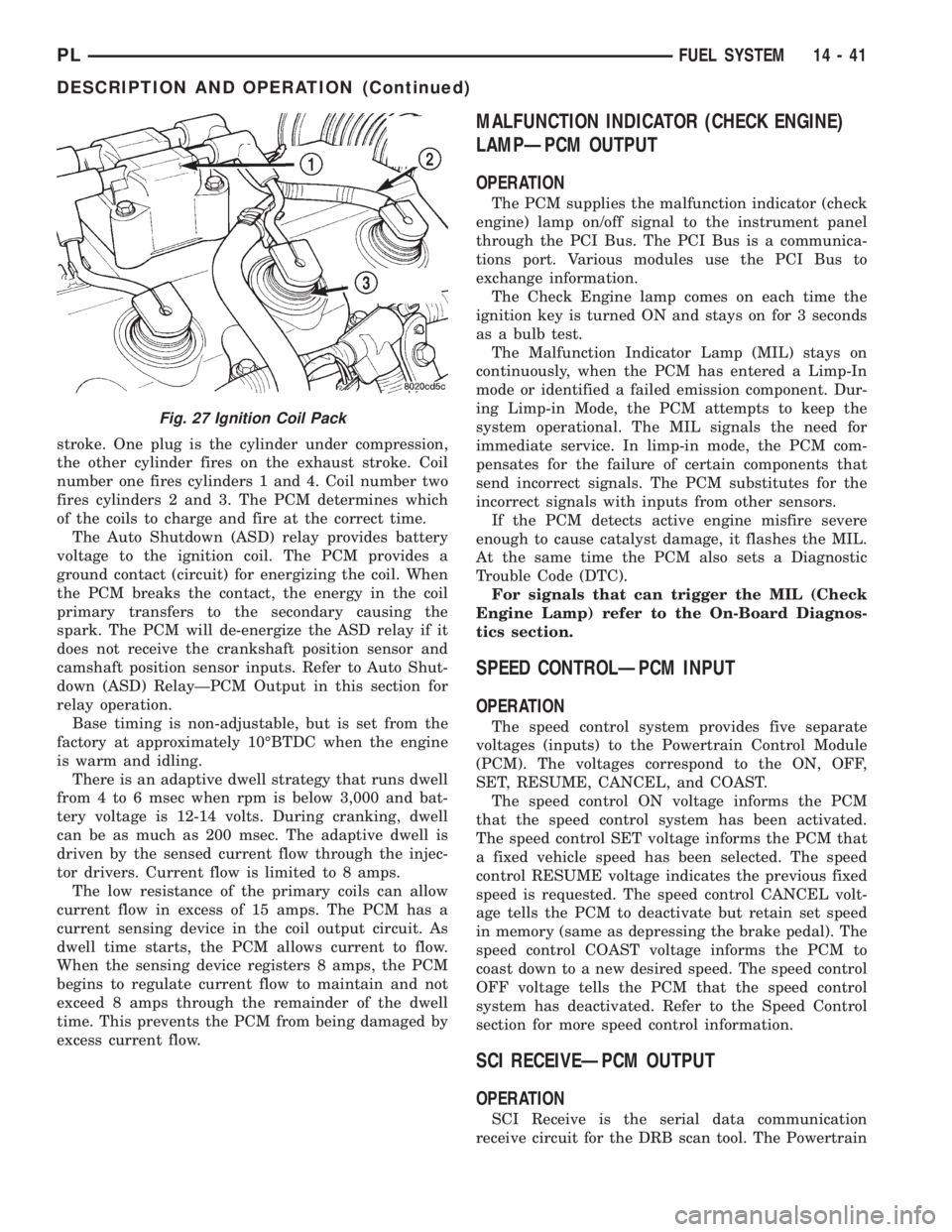
stroke. One plug is the cylinder under compression,
the other cylinder fires on the exhaust stroke. Coil
number one fires cylinders 1 and 4. Coil number two
fires cylinders 2 and 3. The PCM determines which
of the coils to charge and fire at the correct time.
The Auto Shutdown (ASD) relay provides battery
voltage to the ignition coil. The PCM provides a
ground contact (circuit) for energizing the coil. When
the PCM breaks the contact, the energy in the coil
primary transfers to the secondary causing the
spark. The PCM will de-energize the ASD relay if it
does not receive the crankshaft position sensor and
camshaft position sensor inputs. Refer to Auto Shut-
down (ASD) RelayÐPCM Output in this section for
relay operation.
Base timing is non-adjustable, but is set from the
factory at approximately 10ÉBTDC when the engine
is warm and idling.
There is an adaptive dwell strategy that runs dwell
from 4 to 6 msec when rpm is below 3,000 and bat-
tery voltage is 12-14 volts. During cranking, dwell
can be as much as 200 msec. The adaptive dwell is
driven by the sensed current flow through the injec-
tor drivers. Current flow is limited to 8 amps.
The low resistance of the primary coils can allow
current flow in excess of 15 amps. The PCM has a
current sensing device in the coil output circuit. As
dwell time starts, the PCM allows current to flow.
When the sensing device registers 8 amps, the PCM
begins to regulate current flow to maintain and not
exceed 8 amps through the remainder of the dwell
time. This prevents the PCM from being damaged by
excess current flow.
MALFUNCTION INDICATOR (CHECK ENGINE)
LAMPÐPCM OUTPUT
OPERATION
The PCM supplies the malfunction indicator (check
engine) lamp on/off signal to the instrument panel
through the PCI Bus. The PCI Bus is a communica-
tions port. Various modules use the PCI Bus to
exchange information.
The Check Engine lamp comes on each time the
ignition key is turned ON and stays on for 3 seconds
as a bulb test.
The Malfunction Indicator Lamp (MIL) stays on
continuously, when the PCM has entered a Limp-In
mode or identified a failed emission component. Dur-
ing Limp-in Mode, the PCM attempts to keep the
system operational. The MIL signals the need for
immediate service. In limp-in mode, the PCM com-
pensates for the failure of certain components that
send incorrect signals. The PCM substitutes for the
incorrect signals with inputs from other sensors.
If the PCM detects active engine misfire severe
enough to cause catalyst damage, it flashes the MIL.
At the same time the PCM also sets a Diagnostic
Trouble Code (DTC).
For signals that can trigger the MIL (Check
Engine Lamp) refer to the On-Board Diagnos-
tics section.
SPEED CONTROLÐPCM INPUT
OPERATION
The speed control system provides five separate
voltages (inputs) to the Powertrain Control Module
(PCM). The voltages correspond to the ON, OFF,
SET, RESUME, CANCEL, and COAST.
The speed control ON voltage informs the PCM
that the speed control system has been activated.
The speed control SET voltage informs the PCM that
a fixed vehicle speed has been selected. The speed
control RESUME voltage indicates the previous fixed
speed is requested. The speed control CANCEL volt-
age tells the PCM to deactivate but retain set speed
in memory (same as depressing the brake pedal). The
speed control COAST voltage informs the PCM to
coast down to a new desired speed. The speed control
OFF voltage tells the PCM that the speed control
system has deactivated. Refer to the Speed Control
section for more speed control information.
SCI RECEIVEÐPCM OUTPUT
OPERATION
SCI Receive is the serial data communication
receive circuit for the DRB scan tool. The Powertrain
Fig. 27 Ignition Coil Pack
PLFUEL SYSTEM 14 - 41
DESCRIPTION AND OPERATION (Continued)