2000 DODGE NEON check oil
[x] Cancel search: check oilPage 777 of 1285
INSTALLATION
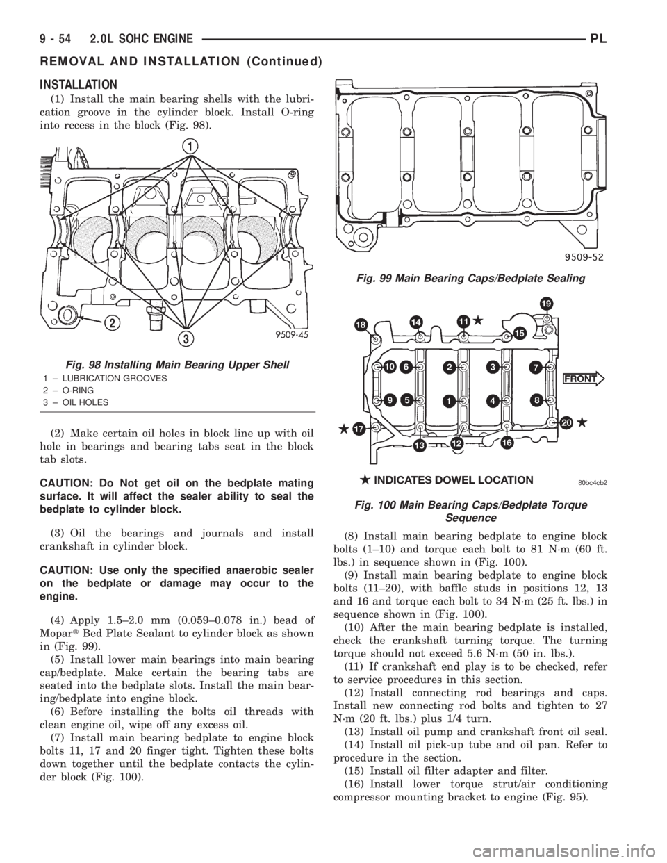
(1) Install the main bearing shells with the lubri-
cation groove in the cylinder block. Install O-ring
into recess in the block (Fig. 98).
(2) Make certain oil holes in block line up with oil
hole in bearings and bearing tabs seat in the block
tab slots.
CAUTION: Do Not get oil on the bedplate mating
surface. It will affect the sealer ability to seal the
bedplate to cylinder block.
(3) Oil the bearings and journals and install
crankshaft in cylinder block.
CAUTION: Use only the specified anaerobic sealer
on the bedplate or damage may occur to the
engine.
(4) Apply 1.5±2.0 mm (0.059±0.078 in.) bead of
MopartBed Plate Sealant to cylinder block as shown
in (Fig. 99).
(5) Install lower main bearings into main bearing
cap/bedplate. Make certain the bearing tabs are
seated into the bedplate slots. Install the main bear-
ing/bedplate into engine block.
(6) Before installing the bolts oil threads with
clean engine oil, wipe off any excess oil.
(7) Install main bearing bedplate to engine block
bolts 11, 17 and 20 finger tight. Tighten these bolts
down together until the bedplate contacts the cylin-
der block (Fig. 100).(8) Install main bearing bedplate to engine block
bolts (1±10) and torque each bolt to 81 N´m (60 ft.
lbs.) in sequence shown in (Fig. 100).
(9) Install main bearing bedplate to engine block
bolts (11±20), with baffle studs in positions 12, 13
and 16 and torque each bolt to 34 N´m (25 ft. lbs.) in
sequence shown in (Fig. 100).
(10) After the main bearing bedplate is installed,
check the crankshaft turning torque. The turning
torque should not exceed 5.6 N´m (50 in. lbs.).
(11) If crankshaft end play is to be checked, refer
to service procedures in this section.
(12) Install connecting rod bearings and caps.
Install new connecting rod bolts and tighten to 27
N´m (20 ft. lbs.) plus 1/4 turn.
(13) Install oil pump and crankshaft front oil seal.
(14) Install oil pick-up tube and oil pan. Refer to
procedure in the section.
(15) Install oil filter adapter and filter.
(16) Install lower torque strut/air conditioning
compressor mounting bracket to engine (Fig. 95).
Fig. 98 Installing Main Bearing Upper Shell
1 ± LUBRICATION GROOVES
2 ± O-RING
3 ± OIL HOLES
Fig. 99 Main Bearing Caps/Bedplate Sealing
Fig. 100 Main Bearing Caps/Bedplate Torque
Sequence
9 - 54 2.0L SOHC ENGINEPL
REMOVAL AND INSTALLATION (Continued)
Page 778 of 1285
(17) Install rear timing belt cover and camshaft
sprocket.
(18) Install crankshaft sprocket, timing belt ten-
sioner, timing belt, and cover.
(19) Install front engine mount bracket.
(20) Remove engine from repair stand and position
on Special Tools 6135 and 6710 Engine Dolly and
Cradle. Install safety straps around the engine to
cradle and tighten and lock them into position.
(21) Install crankshaft rear oil seal. Refer to proce-
dure in this section.
(22) Install drive plate/flywheel. Apply Mopart
Lock & Seal Adhesive to bolt threads and tighten to
95 N´m (70 ft. lbs.).
(23) Install transaxle to engine.
(24) Install structural collar. Refer to procedure in
this section.
(25) Install engine assembly. Refer to procedure in
this section.
(26) Perform camshaft and crankshaft timing
relearn procedure as follows:
²Connect the DRB scan tool to the data link
(diagnostic) connector. This connector is located in
the passenger compartment; at the lower edge of
instrument panel; near the steering column.
²Turn the ignition switch on and access the ªmis-
cellaneousº screen.
²Select ªre-learn cam/crankº option and follow
directions on DRB screen.
OIL FILTER ADAPTER
REMOVE AND INSTALL
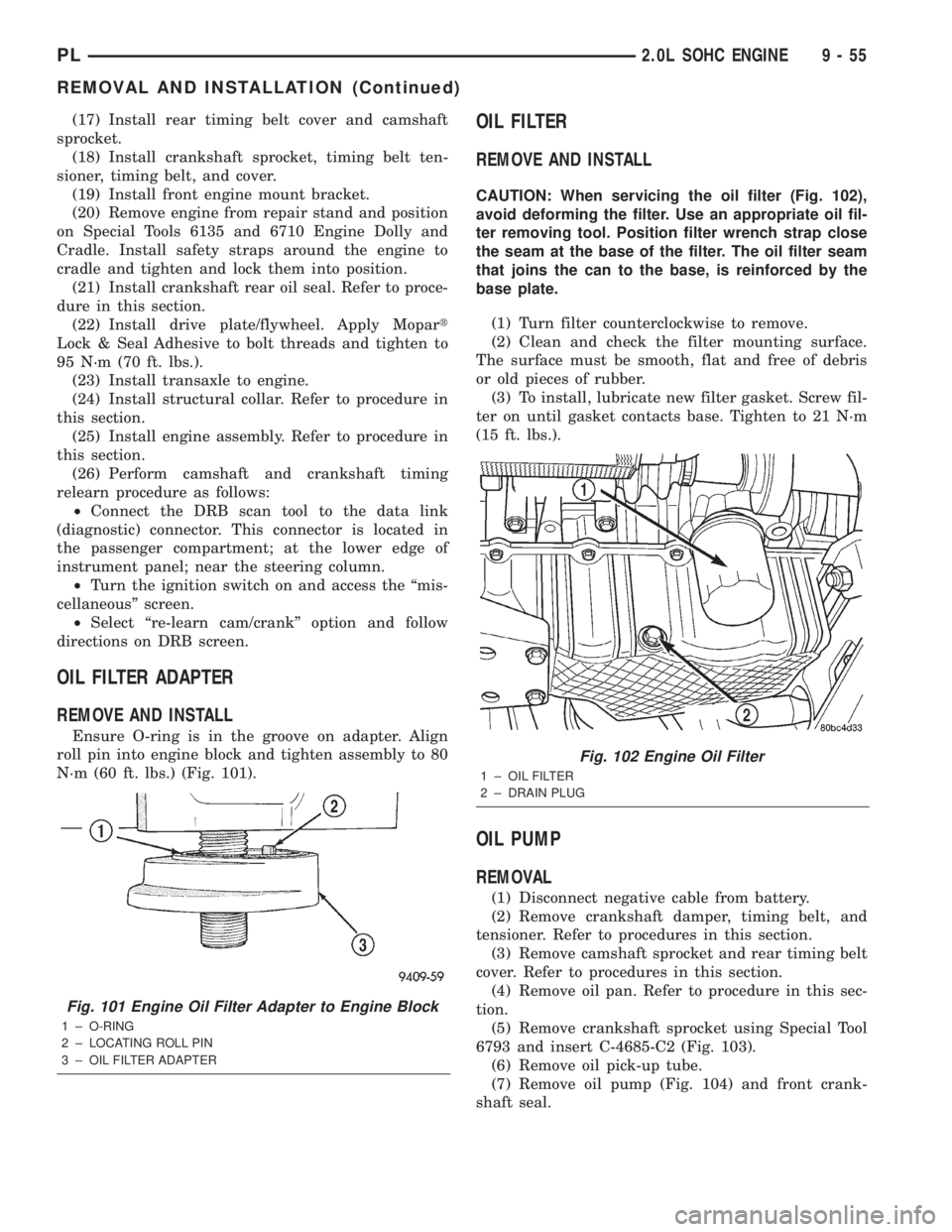
Ensure O-ring is in the groove on adapter. Align
roll pin into engine block and tighten assembly to 80
N´m (60 ft. lbs.) (Fig. 101).
OIL FILTER
REMOVE AND INSTALL
CAUTION: When servicing the oil filter (Fig. 102),
avoid deforming the filter. Use an appropriate oil fil-
ter removing tool. Position filter wrench strap close
the seam at the base of the filter. The oil filter seam
that joins the can to the base, is reinforced by the
base plate.
(1) Turn filter counterclockwise to remove.
(2) Clean and check the filter mounting surface.
The surface must be smooth, flat and free of debris
or old pieces of rubber.
(3) To install, lubricate new filter gasket. Screw fil-
ter on until gasket contacts base. Tighten to 21 N´m
(15 ft. lbs.).
OIL PUMP
REMOVAL
(1) Disconnect negative cable from battery.
(2) Remove crankshaft damper, timing belt, and
tensioner. Refer to procedures in this section.
(3) Remove camshaft sprocket and rear timing belt
cover. Refer to procedures in this section.
(4) Remove oil pan. Refer to procedure in this sec-
tion.
(5) Remove crankshaft sprocket using Special Tool
6793 and insert C-4685-C2 (Fig. 103).
(6) Remove oil pick-up tube.
(7) Remove oil pump (Fig. 104) and front crank-
shaft seal.
Fig. 101 Engine Oil Filter Adapter to Engine Block
1 ± O-RING
2 ± LOCATING ROLL PIN
3 ± OIL FILTER ADAPTER
Fig. 102 Engine Oil Filter
1 ± OIL FILTER
2 ± DRAIN PLUG
PL2.0L SOHC ENGINE 9 - 55
REMOVAL AND INSTALLATION (Continued)
Page 783 of 1285
(10) Install connecting rod lower bearing half and
cap. InstallNewbolts and tighten to 27 N´m (20 ft.
lbs.) plus 1/4 turn.
(11) Install cylinder head and oil pan. Refer to pro-
cedures in this section.
DISASSEMBLY AND ASSEMBLY
OIL PUMP
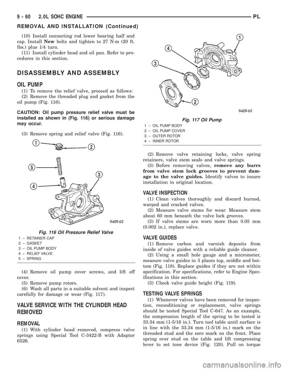
(1) To remove the relief valve, proceed as follows:
(2) Remove the threaded plug and gasket from the
oil pump (Fig. 116).
CAUTION: Oil pump pressure relief valve must be
installed as shown in (Fig. 116) or serious damage
may occur.
(3) Remove spring and relief valve (Fig. 116).
(4) Remove oil pump cover screws, and lift off
cover.
(5) Remove pump rotors.
(6) Wash all parts in a suitable solvent and inspect
carefully for damage or wear (Fig. 117).
VALVE SERVICE WITH THE CYLINDER HEAD
REMOVED
REMOVAL
(1) With cylinder head removed, compress valve
springs using Special Tool C-3422-B with Adaptor
6526.(2) Remove valve retaining locks, valve spring
retainers, valve stem seals and valve springs.
(3) Before removing valves,remove any burrs
from valve stem lock grooves to prevent dam-
age to the valve guides.Identify valves to insure
installation in original location.
VALVE INSPECTION
(1) Clean valves thoroughly and discard burned,
warped and cracked valves.
(2) Measure valve stems for wear. Measure stem
about 60 mm beneath the valve lock grooves.
(3) If valve stems are worn more than 0.05 mm
(0.002 in.), replace valve.
VALVE GUIDES
(1) Remove carbon and varnish deposits from
inside of valve guides with a reliable guide cleaner.
(2) Using a small hole gauge and a micrometer,
measure valve guides in 3 places top, middle and bot-
tom (Fig. 118). Replace guides if they are not within
specification. For specifications, refer to Engine Spec-
ifications in this section.
(3) Check valve guide height (Fig. 119).
TESTING VALVE SPRINGS
(1) Whenever valves have been removed for inspec-
tion, reconditioning or replacement, valve springs
should be tested Special Tool C-647. As an example,
the compression length of the spring to be tested is
33.34 mm (1-5/16 in.). Turn tool table until surface is
in line with the 33.34 mm (1-5/16 in.) mark on the
threaded stud and the zero mark on the front. Place
spring over stud on the table and lift compressing
lever to set tone device (Fig. 120). Pull on torque
Fig. 116 Oil Pressure Relief Valve
1 ± RETAINER CAP
2 ± GASKET
3 ± OIL PUMP BODY
4 ± RELIEF VALVE
5 ± SPRING
Fig. 117 Oil Pump
1 ± OIL PUMP BODY
2 ± OIL PUMP COVER
3 ± OUTER ROTOR
4 ± INNER ROTOR
9 - 60 2.0L SOHC ENGINEPL
REMOVAL AND INSTALLATION (Continued)
Page 785 of 1285
then set valve in place. Rotate the valve with light
pressure. If the blue is transferred to the center of
valve face, contact is satisfactory. If the blue is trans-
ferred to top edge of the valve face, lower valve seat
with a 15 degrees stone. If the blue is transferred to
the bottom edge of valve face raise valve seat with a
65 degrees stone.
(6) Valve seats which are worn or burned can be
reworked, provided that correct angle and seat width
are maintained. The intake valve seat must be ser-
viced when the valve seat width is 2.0 mm (0.079 in.)
or greater. The exhaust valve seat must be serviced
when the valve seat width is 2.5 mm (0.098 in.) or
greater. Otherwise the cylinder head must be
replaced.
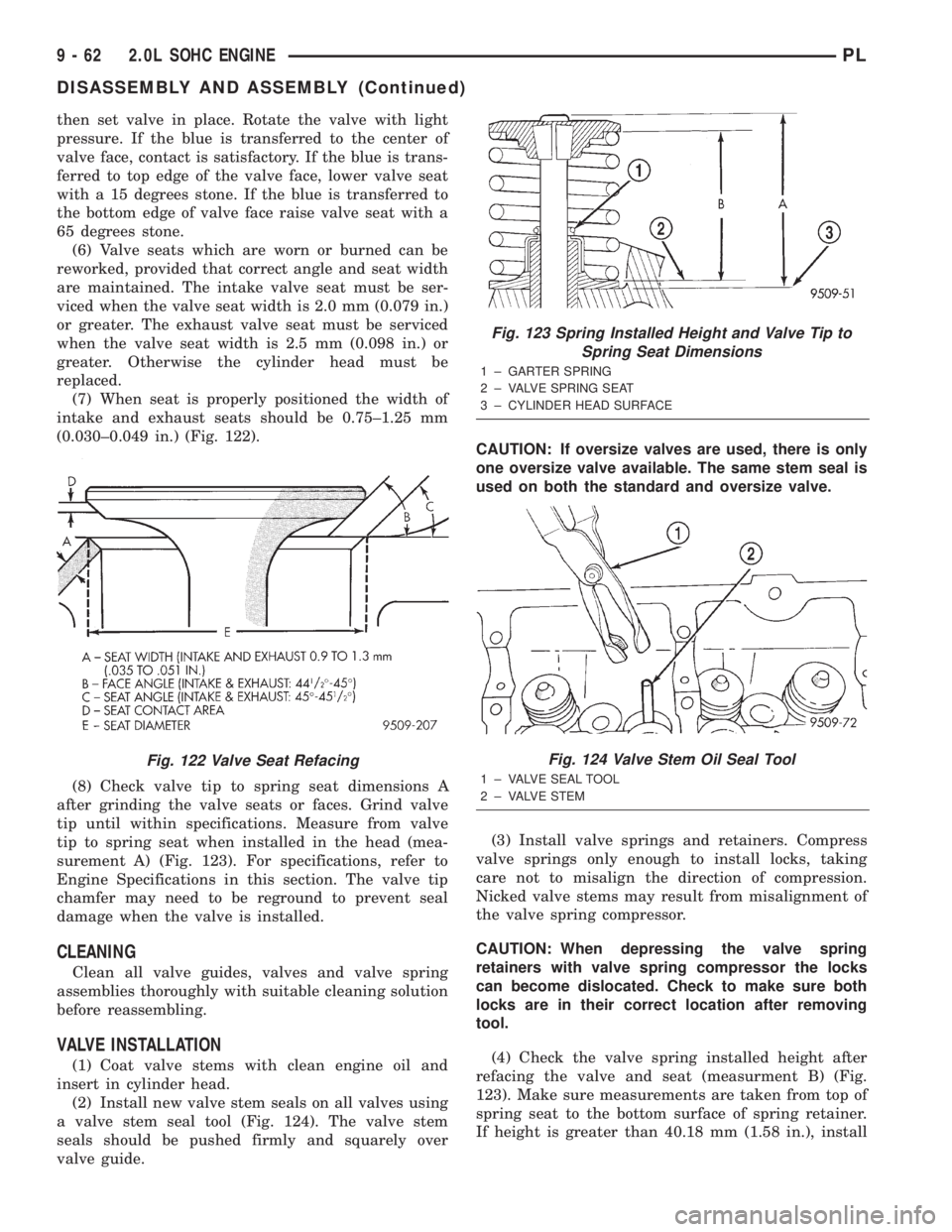
(7) When seat is properly positioned the width of
intake and exhaust seats should be 0.75±1.25 mm
(0.030±0.049 in.) (Fig. 122).
(8) Check valve tip to spring seat dimensions A
after grinding the valve seats or faces. Grind valve
tip until within specifications. Measure from valve
tip to spring seat when installed in the head (mea-
surement A) (Fig. 123). For specifications, refer to
Engine Specifications in this section. The valve tip
chamfer may need to be reground to prevent seal
damage when the valve is installed.
CLEANING
Clean all valve guides, valves and valve spring
assemblies thoroughly with suitable cleaning solution
before reassembling.
VALVE INSTALLATION
(1) Coat valve stems with clean engine oil and
insert in cylinder head.
(2) Install new valve stem seals on all valves using
a valve stem seal tool (Fig. 124). The valve stem
seals should be pushed firmly and squarely over
valve guide.CAUTION: If oversize valves are used, there is only
one oversize valve available. The same stem seal is
used on both the standard and oversize valve.
(3) Install valve springs and retainers. Compress
valve springs only enough to install locks, taking
care not to misalign the direction of compression.
Nicked valve stems may result from misalignment of
the valve spring compressor.
CAUTION: When depressing the valve spring
retainers with valve spring compressor the locks
can become dislocated. Check to make sure both
locks are in their correct location after removing
tool.
(4) Check the valve spring installed height after
refacing the valve and seat (measurment B) (Fig.
123). Make sure measurements are taken from top of
spring seat to the bottom surface of spring retainer.
If height is greater than 40.18 mm (1.58 in.), install
Fig. 122 Valve Seat Refacing
Fig. 123 Spring Installed Height and Valve Tip to
Spring Seat Dimensions
1 ± GARTER SPRING
2 ± VALVE SPRING SEAT
3 ± CYLINDER HEAD SURFACE
Fig. 124 Valve Stem Oil Seal Tool
1 ± VALVE SEAL TOOL
2 ± VALVE STEM
9 - 62 2.0L SOHC ENGINEPL
DISASSEMBLY AND ASSEMBLY (Continued)
Page 786 of 1285
a 0.762 mm (0.030 in.) spacer under the valve spring
seat to bring spring height back within specification.
(5) Install rocker arm shafts as previously
described in this section.
(6) Checking dry lash. Dry lash is the amount of
clearance that exists between the base circle of an
installed cam and the rocker arm roller when the
adjuster is drained of oil and completely collapsed.
Specified dry lash is 1.17 mm (0.046 in.) for intake
and 1.28 mm (0.050 in.) for exhaust. After performing
dry lash check, refill adjuster with oil and allow 10
minutes for adjuster(s) to bleed down before rotating
cam.
CLEANING AND INSPECTION
INTAKE MANIFOLD
CLEAN AND INSPECT
Check for:
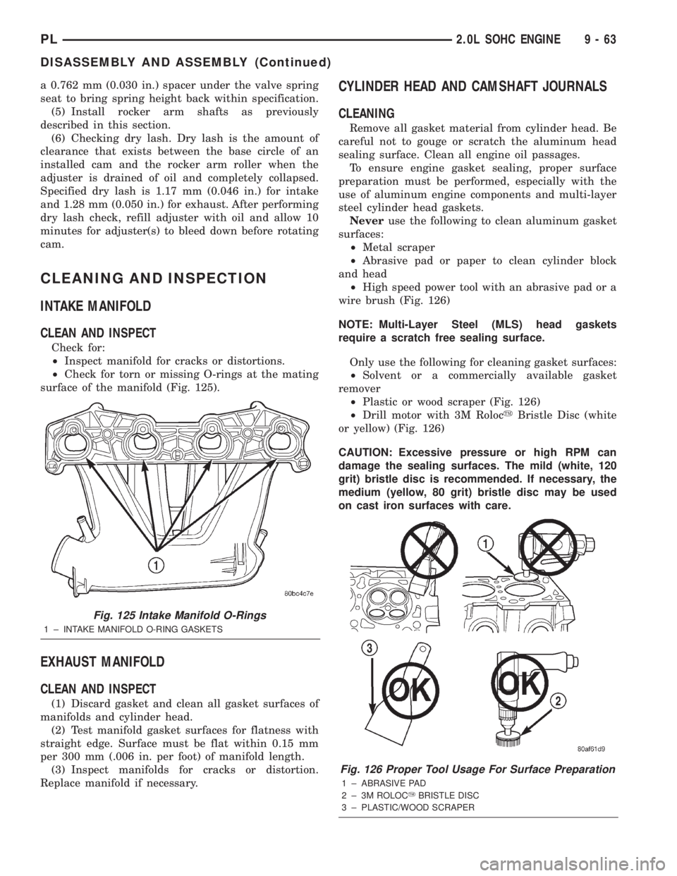
²Inspect manifold for cracks or distortions.
²Check for torn or missing O-rings at the mating
surface of the manifold (Fig. 125).
EXHAUST MANIFOLD
CLEAN AND INSPECT
(1) Discard gasket and clean all gasket surfaces of
manifolds and cylinder head.
(2) Test manifold gasket surfaces for flatness with
straight edge. Surface must be flat within 0.15 mm
per 300 mm (.006 in. per foot) of manifold length.
(3) Inspect manifolds for cracks or distortion.
Replace manifold if necessary.
CYLINDER HEAD AND CAMSHAFT JOURNALS
CLEANING
Remove all gasket material from cylinder head. Be
careful not to gouge or scratch the aluminum head
sealing surface. Clean all engine oil passages.
To ensure engine gasket sealing, proper surface
preparation must be performed, especially with the
use of aluminum engine components and multi-layer
steel cylinder head gaskets.
Neveruse the following to clean aluminum gasket
surfaces:
²Metal scraper
²Abrasive pad or paper to clean cylinder block
and head
²High speed power tool with an abrasive pad or a
wire brush (Fig. 126)
NOTE: Multi-Layer Steel (MLS) head gaskets
require a scratch free sealing surface.
Only use the following for cleaning gasket surfaces:
²Solvent or a commercially available gasket
remover
²Plastic or wood scraper (Fig. 126)
²Drill motor with 3M RolocyBristle Disc (white
or yellow) (Fig. 126)
CAUTION: Excessive pressure or high RPM can
damage the sealing surfaces. The mild (white, 120
grit) bristle disc is recommended. If necessary, the
medium (yellow, 80 grit) bristle disc may be used
on cast iron surfaces with care.
Fig. 125 Intake Manifold O-Rings
1 ± INTAKE MANIFOLD O-RING GASKETS
Fig. 126 Proper Tool Usage For Surface Preparation
1 ± ABRASIVE PAD
2 ± 3M ROLOCYBRISTLE DISC
3 ± PLASTIC/WOOD SCRAPER
PL2.0L SOHC ENGINE 9 - 63
DISASSEMBLY AND ASSEMBLY (Continued)
Page 787 of 1285
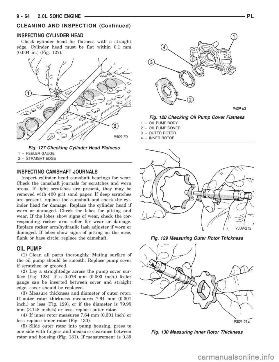
INSPECTING CYLINDER HEAD
Check cylinder head for flatness with a straight
edge. Cylinder head must be flat within 0.1 mm
(0.004 in.) (Fig. 127).
INSPECTING CAMSHAFT JOURNALS
Inspect cylinder head camshaft bearings for wear.
Check the camshaft journals for scratches and worn
areas. If light scratches are present, they may be
removed with 400 grit sand paper. If deep scratches
are present, replace the camshaft and check the cyl-
inder head for damage. Replace the cylinder head if
worn or damaged. Check the lobes for pitting and
wear. If the lobes show signs of wear, check the cor-
responding rocker arm roller for wear or damage.
Replace rocker arm/hydraulic lash adjuster if worn or
damaged. If lobes show signs of pitting on the nose,
flank or base circle; replace the camshaft.
OIL PUMP
(1) Clean all parts thoroughly. Mating surface of
the oil pump should be smooth. Replace pump cover
if scratched or grooved.
(2) Lay a straightedge across the pump cover sur-
face (Fig. 128). If a 0.076 mm (0.003 inch.) feeler
gauge can be inserted between cover and straight
edge, cover should be replaced.
(3) Measure thickness and diameter of outer rotor.
If outer rotor thickness measures 7.64 mm (0.301
inch.) or less (Fig. 129), or if the diameter is 79.95
mm (3.148 inches) or less, replace outer rotor.
(4) If inner rotor measures 7.64 mm (0.301 inch) or
less replace inner rotor (Fig. 130).
(5) Slide outer rotor into pump housing, press to
one side with fingers and measure clearance between
rotor and housing (Fig. 131). If measurement is 0.39
Fig. 127 Checking Cylinder Head Flatness
1 ± FEELER GAUGE
2 ± STRAIGHT EDGE
Fig. 128 Checking Oil Pump Cover Flatness
1 ± OIL PUMP BODY
2 ± OIL PUMP COVER
3 ± OUTER ROTOR
4 ± INNER ROTOR
Fig. 129 Measuring Outer Rotor Thickness
Fig. 130 Measuring Inner Rotor Thickness
9 - 64 2.0L SOHC ENGINEPL
CLEANING AND INSPECTION (Continued)
Page 788 of 1285
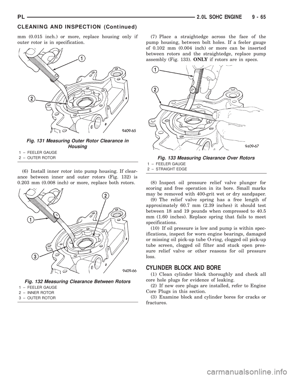
mm (0.015 inch.) or more, replace housing only if
outer rotor is in specification.
(6) Install inner rotor into pump housing. If clear-
ance between inner and outer rotors (Fig. 132) is
0.203 mm (0.008 inch) or more, replace both rotors.(7) Place a straightedge across the face of the
pump housing, between bolt holes. If a feeler gauge
of 0.102 mm (0.004 inch) or more can be inserted
between rotors and the straightedge, replace pump
assembly (Fig. 133).ONLYif rotors are in specs.
(8) Inspect oil pressure relief valve plunger for
scoring and free operation in its bore. Small marks
may be removed with 400-grit wet or dry sandpaper.
(9) The relief valve spring has a free length of
approximately 60.7 mm (2.39 inches) it should test
between 18 and 19 pounds when compressed to 40.5
mm (1.60 inches). Replace spring that fails to meet
specifications.
(10) If oil pressure is low and pump is within spec-
ifications, inspect for worn engine bearings, damaged
or missing oil pick-up tube O-ring, clogged oil pick-up
tube screen, clogged oil filter and stuck open pres-
sure relief valve or other reasons for oil pressure
loss.
CYLINDER BLOCK AND BORE
(1) Clean cylinder block thoroughly and check all
core hole plugs for evidence of leaking.
(2) If new core plugs are installed, refer to Engine
Core Plugs in this section.
(3) Examine block and cylinder bores for cracks or
fractures.
Fig. 131 Measuring Outer Rotor Clearance in
Housing
1 ± FEELER GAUGE
2 ± OUTER ROTOR
Fig. 132 Measuring Clearance Between Rotors
1 ± FEELER GAUGE
2 ± INNER ROTOR
3 ± OUTER ROTOR
Fig. 133 Measuring Clearance Over Rotors
1 ± FEELER GAUGE
2 ± STRAIGHT EDGE
PL2.0L SOHC ENGINE 9 - 65
CLEANING AND INSPECTION (Continued)
Page 801 of 1285
DIAGNOSIS AND TESTING
EXHAUST SYSTEM DIAGNOSIS CHART
CONDITION POSSIBLE CAUSES CORRECTION
EXCESSIVE
EXHAUST NOISE
(UNDER HOOD)1. Exhaust manifold cracked or broken. 1. Replace manifold.
2. Manifold to cylinder head leak. 2. Tighten manifold and/or replace gasket.
3. Exhaust Flex joint to manifold leak. 3. Tighten fasteners or replace gasket.
4. Exhaust flex joint. 4. Replace catalytic converter assembly.
5. Pipe and shell noise from front exhaust
pipe.5. Characteristic of single wall pipes.
EXCESSIVE
EXHAUST NOISE1. Leaks at pipe joints. 1. Tighten or replace clamps at leaking
joints.
2. Burned, blown, or rusted out exhaust
pipe or muffler.2. Replace muffler or exhaust pipes.
3. Restriction in muffler or tailpipe. 3. Remove restriction, if possible or replace
as necessary.
4. Catalytic converter material in muffler. 4. Replace muffler and converter assembly.
Check fuel injection and ignition systems for
proper operation.
REMOVAL AND INSTALLATION
EXHAUST PIPE AND MUFFLER
REMOVAL
WARNING: THE NORMAL OPERATING TEMPERA-
TURE OF THE EXHAUST SYSTEM IS VERY HIGH.
THEREFORE, NEVER WORK AROUND OR ATTEMPT
TO SERVICE ANY PART OF THE EXHAUST SYSTEM
UNTIL IT IS COOLED. SPECIAL CARE SHOULD BE
TAKEN WHEN WORKING NEAR THE CATALYTIC
CONVERTER. THE TEMPERATURE OF THE CON-
VERTER RISES TO A HIGH LEVEL AFTER A SHORT
PERIOD OF ENGINE OPERATING TIME.
(1) Raise vehicle on hoist and apply penetrating oil
to band clamp fastener of component being removed.
NOTE: Do not use petroleum-based lubricants
when removing/installing muffler or exhaust pipe
isolators as it may compromise the life of the part.
A suitable substitute is a mixture of liquid dish
soap and water.
(2) Remove exhaust system ground strap.
(3) Loosen band clamp and remove support isola-
tors at muffler. Remove muffler from exhaust pipe
(Fig. 7).(4) Loosen band clamp at the catalytic converter to
intermediate pipe joint (Fig. 7)
(5) Remove intermediate pipe support isolator.
Separate at slip joint and remove intermediate pipe
(Fig. 7).
(6) Clean ends of pipes and muffler to assure mat-
ing of all parts. Discard broken or worn isolators,
rusted or overused clamps, supports, and attaching
parts.
NOTE: When replacement is required on any com-
ponent of the exhaust system, you must use origi-
nal equipment parts (or their equivalent).
INSTALLATION
When assembling exhaust systemdo nottighten
clamps until components are aligned and clearances
are checked.
(1) Assemble intermediate pipe to catalytic con-
verter and the isolator support to the underbody (Fig.
7).
(2) Install the muffler to intermediate pipe and the
isolator supports to the underbody.
(3) Working from the front of system; align each
component to maintain position and proper clearance
with underbody parts (Fig. 9). Tighten band clamps
to 47 N´m (35 ft. lbs.) (Fig. 8).
11 - 4 EXHAUST SYSTEMPL