2000 DODGE NEON check oil
[x] Cancel search: check oilPage 197 of 1285
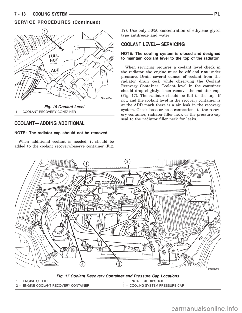
COOLANTÐADDING ADDITIONAL
NOTE: The radiator cap should not be removed.
When additional coolant is needed, it should be
added to the coolant recovery/reserve container (Fig.17). Use only 50/50 concentration of ethylene glycol
type antifreeze and water
COOLANT LEVELÐSERVICING
NOTE: The cooling system is closed and designed
to maintain coolant level to the top of the radiator.
When servicing requires a coolant level check in
the radiator, the engine must beoffandnotunder
pressure. Drain several ounces of coolant from the
radiator drain cock while observing the Coolant
Recovery Container. Coolant level in the container
should drop slightly. Then remove the radiator cap,
(Fig. 17). The radiator should be full to the top. If
not, and the coolant level in the recovery container is
at the ADD mark there is a air leak in the recovery
system. Check hose or hose connections to the recov-
ery container, radiator filler neck or the pressure cap
seal to the radiator filler neck for leaks.
Fig. 17 Coolant Recovery Container and Pressure Cap Locations
1 ± ENGINE OIL FILL
2 ± ENGINE COOLANT RECOVERY CONTAINER3 ± ENGINE OIL DIPSTICK
4 ± COOLING SYSTEM PRESSURE CAP
Fig. 16 Coolant Level
1 ± COOLANT RECOVERY CONTAINER
7 - 18 COOLING SYSTEMPL
SERVICE PROCEDURES (Continued)
Page 224 of 1285
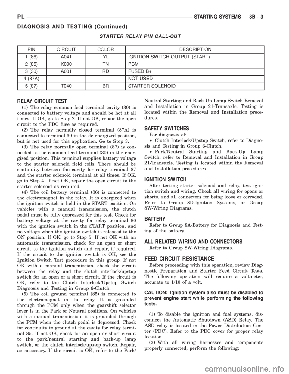
STARTER RELAY PIN CALL-OUT
PIN CIRCUIT COLOR DESCRIPTION
1 (86) A041 YL IGNITION SWITCH OUTPUT (START)
2 (85) K090 TN PCM
3 (30) A001 RD FUSED B+
4 (87A) NOT USED
5 (87) T040 BR STARTER SOLENOID
RELAY CIRCUIT TEST
(1) The relay common feed terminal cavity (30) is
connected to battery voltage and should be hot at all
times. If OK, go to Step 2. If not OK, repair the open
circuit to the PDC fuse as required.
(2) The relay normally closed terminal (87A) is
connected to terminal 30 in the de-energized position,
but is not used for this application. Go to Step 3.
(3) The relay normally open terminal (87) is con-
nected to the common feed terminal (30) in the ener-
gized position. This terminal supplies battery voltage
to the starter solenoid field coils. There should be
continuity between the cavity for relay terminal 87
and the starter solenoid terminal at all times. If OK,
go to Step 4. If not OK, repair the open circuit to the
starter solenoid as required.
(4) The coil battery terminal (86) is connected to
the electromagnet in the relay. It is energized when
the ignition switch is held in the START position. On
vehicles with a manual transmission, the clutch
pedal must be fully depressed for this test. Check for
battery voltage at the cavity for relay terminal 86
with the ignition switch in the START position, and
no voltage when the ignition switch is released to the
ON position. If OK, go to Step 5. If not OK with an
automatic transmission, check for an open or short
circuit to the ignition switch and repair, if required.
If the circuit to the ignition switch is OK, see the
Ignition Switch Test procedure in this group. If not
OK with a manual transmission, check the circuit
between the relay and the clutch interlock/upstop
switch for an open or a short circuit. If the circuit is
OK, refer to the Clutch Interlock/Upstop Switch
Diagnosis and Testing in Group 6-Clutch.
(5) The coil ground terminal (85) is connected to
the electromagnet in the relay. It is grounded
through the PCM only when the gearshift selector
lever is in the Park or Neutral positions. On vehicles
with a manual transmission, it is grounded through
the PCM when the clutch pedal is depressed. Check
for continuity to ground at the cavity for relay termi-
nal 85. If not OK, check for an open or short circuit
to the park/neutral starting and back-up lamp
switch, or the clutch interlock/upstop switch. Repair,
as necessary. If the circuit is OK, refer to the Park/Neutral Starting and Back-Up Lamp Switch Removal
and Installation in Group 21-Transaxle. Testing is
located within the Removal and Installation proce-
dures.
SAFETY SWITCHES
For diagnosis of:
²Clutch Interlock/Upstop Switch, refer to Diagno-
sis and Testing in Group 6-Clutch.
²Park/Neutral Starting and Back-Up Lamp
Switch, refer to Removal and Installation in Group
21-Transaxle. Testing is located within the Removal
and Installation procedures.
IGNITION SWITCH
After testing starter solenoid and relay, test igni-
tion switch and wiring. Check all wiring for opens or
shorts, and all connectors for being loose or corroded.
Refer to Group 8D-Ignition Systems, or Group
8W-Wiring Diagrams.
BATTERY
Refer to Group 8A-Battery for Diagnosis and Test-
ing of the battery.
ALL RELATED WIRING AND CONNECTORS
Refer to Group 8W-Wiring Diagrams.
FEED CIRCUIT RESISTANCE
Before proceeding with this operation, review Diag-
nostic Preparation and Starter Feed Circuit Tests.
The following operation will require a voltmeter,
accurate to 1/10 of a volt.
CAUTION: Ignition system also must be disabled to
prevent engine start while performing the following
tests.
(1) To disable the ignition and fuel systems, dis-
connect the Automatic Shutdown (ASD) Relay. The
ASD relay is located in the Power Distribution Cen-
ter (PDC). Refer to the PDC cover for proper relay
location.
(2) With all wiring harnesses and components
properly connected, perform the following:
PLSTARTING SYSTEMS 8B - 3
DIAGNOSIS AND TESTING (Continued)
Page 236 of 1285
IGNITION SYSTEM
TABLE OF CONTENTS
page page
DESCRIPTION AND OPERATION
IGNITION SYSTEM........................1
SPARK PLUGS...........................1
SPARK PLUG CABLES.....................1
ELECTRONIC IGNITION COILS...............2
AUTOMATIC SHUTDOWN RELAY.............2
CRANKSHAFT POSITION SENSORÐPCM
INPUT................................3
CAMSHAFT POSITION SENSORÐPCM
INPUT................................4
KNOCK SENSOR..........................5
IGNITION SWITCH........................5
LOCK KEY CYLINDER......................5
IGNITION INTERLOCK.....................6
REMOVAL AND INSTALLATION
SPARK PLUG SERVICE....................6SPARK PLUG CABLE SERVICE..............6
IGNITION COIL...........................6
AUTOMATIC SHUTDOWN RELAY.............6
CAMSHAFT POSITION SENSOR..............6
CRANKSHAFT POSITION SENSOR............8
KNOCK SENSOR..........................8
IGNITION SWITCH........................8
LOCK KEY CYLINDER......................9
IGNITION INTERLOCK....................10
SPECIFICATIONS
VECI LABEL............................10
FIRING ORDERÐ2.0L....................10
TORQUE SPECIFICATION..................11
SPARK PLUG CABLE RESISTANCEÐSOHC....11
SPARK PLUG...........................11
IGNITION COIL..........................11
DESCRIPTION AND OPERATION
IGNITION SYSTEM
DESCRIPTION
The system's three main components are the coil
pack, crankshaft position sensor, and camshaft posi-
tion sensor.
OPERATION
Basic ignition timing is not adjustable.The
Powertrain Control Module (PCM) determines spark
advance. The 2.0L engines use a fixed ignition timing
system. The distributorless electronic ignition system
is referred to as the Direct Ignition System (DIS).
SPARK PLUGS
The 2.0L engines uses resistor spark plugs. For
spark plug identification and specifications, Refer to
the Specifications section at the end of this group.
Remove the spark plugs and examine them for
burned electrodes and fouled, cracked or broken por-
celain insulators. Keep plugs arranged in the order
in which they were removed from the engine. An iso-
lated plug displaying an abnormal condition indicates
that a problem exists in the corresponding cylinder.
Spark plugs that have low mileage may be cleaned
and reused if not otherwise defective. Refer to the
Spark Plug Condition section of this group. Aftercleaning, file the center electrode flat with a small
point file or jewelers file. Adjust the gap between the
electrodes (Fig. 1) to the dimensions specified in the
chart at the end of this section by bending the
ground electrode (just above the attachment weld)
with the appropriate tool.
Never apply any force between the electrode or
damage to the center electrode assembly will result.
Always tighten spark plugs to the specified torque.
Over tightening can cause distortion and damage.
Tighten spark plugs to 28 N´m (20 ft. lbs.) torque.
SPARK PLUG CABLES
Spark plug cables are sometimes referred to as sec-
ondary ignition wires. The wires transfer electrical
current from the coil pack to individual spark plugs
at each cylinder. The resistor type, nonmetallic spark
plug cables provide suppression of radio frequency
emissions from the ignition system.
Check the spark plug cable connections for good
contact at the coil and spark plugs. Terminals should
be fully seated. The nipples and spark plug covers
should be in good condition. Nipples should fit tightly
on the coil. Spark plug boot should completely cover
the spark plug hole in the cylinder head cover. Install
the boot until the terminal snaps over the spark
plug. A snap must be felt to ensure the spark plug
cable terminal engaged the spark plug.
PLIGNITION SYSTEM 8D - 1
Page 237 of 1285

Loose cable connections will corrode, increase resis-
tance and permit water to enter the coil towers.
These conditions can cause ignition malfunction.
Plastic clips in various locations protect the cables
from damage. When the cables are replaced the clips
must be used to prevent damage to the cables, and
should be rotated about 30É below the horizontal.
ELECTRONIC IGNITION COILS
DESCRIPTION
The coil pack consists of 2 coils molded together.
The coil pack is mounted on the valve cover (Fig. 2).
OPERATION
WARNING: THE DIRECT IGNITION SYSTEM GEN-
ERATES APPROXIMATELY 40,000 VOLTS. PER-
SONAL INJURY COULD RESULT FROM CONTACT
WITH THIS SYSTEM.
High tension leads route to each cylinder from the
coil. The coil fires two spark plugs every power
stroke. One plug is the cylinder under compression,
the other cylinder fires on the exhaust stroke. Coil
number one fires cylinders 1 and 4. Coil number two
fires cylinders 2 and 3. The PCM determines which
of the coils to charge and fire at the correct time.
The Auto Shutdown (ASD) relay provides battery
voltage to the ignition coil. The PCM provides a
ground contact (circuit) for energizing the coil. When
the PCM breaks the contact, the energy in the coil
primary transfers to the secondary causing thespark. The PCM will de-energize the ASD relay if it
does not receive the crankshaft position sensor and
camshaft position sensor inputs. Refer to Auto Shut-
down (ASD) RelayÐPCM Output, in this section for
relay operation.
AUTOMATIC SHUTDOWN RELAY
DESCRIPTION
The ASD relay is located in the PDC (Fig. 3). The
inside top of the PDC cover has label showing relay
and fuse identification.
Fig. 1 Checking Spark Plug Electrode Gap
1 ± TAPER GAUGE
Fig. 2 Ignition Coil Pack
1 ± IGNITION COILS
2 ± SPARK PLUG CABLE
3 ± SPARK PLUG INSULATOR
Fig. 3 Power Distribution Center (PDC)
8D - 2 IGNITION SYSTEMPL
DESCRIPTION AND OPERATION (Continued)
Page 241 of 1285
IGNITION INTERLOCK
OPERATION
All vehicles equipped with automatic transaxles
have an interlock system. The system prevents shift-
ing the vehicle out of Park unless the ignition lock
cylinder is in the Off, Run or Start position. In addi-
tion, the operator cannot rotate the key to the lock
position unless the shifter is in the park position. On
vehicles equipped with floor shift refer to the - Tran-
saxle for Automatic Transmission Shifter/Ignition
Interlock.
REMOVAL AND INSTALLATION
SPARK PLUG SERVICE
Failure to route the cables properly could cause the
radio to reproduce ignition noise, cross ignition of the
spark plugs or short circuit the cables to ground.
REMOVAL
REMOVE CABLES FROM COIL FIRST.
Always remove the spark plug cable by grasping
the top of the spark plug insulator, turning the boot
1/2 turn and pulling straight up in a steady motion.
(1) Remove the spark plug using a quality socket
with a rubber or foam insert.
(2) Inspect the spark plug condition.
INSTALLATION
(1) To avoid cross threading, start the spark plug
into the cylinder head by hand.
(2) Tighten spark plugs to 28 N´m (20 ft. lbs.)
torque.
(3) Install spark plug insulators over spark plugs.
Ensure the top of the spark plug insulator covers the
upper end of the spark plug tube.
Reconnect to coil.
SPARK PLUG CABLE SERVICE
Failure to route the cables properly could cause the
radio to reproduce ignition noise, cross ignition of the
spark plugs or short circuit the cables to ground.
REMOVAL
Remove spark plug cable from coil first.
Always remove the spark plug cable by grasping
the top of the spark plug insulator, turning the boot
1/2 turn and pulling straight up in a steady motion.
INSTALLATION
Install spark plug insulators over spark plugs.
Ensure the top of the spark plug insulator covers the
upper end of the spark plug tube. The connect theother end to coil pack. Be sure that dual plastic clip
holds the cables off of the valve cover.
IGNITION COIL
The electronic ignition coil pack attaches directly
to the valve cover (Fig. 11).
REMOVAL
(1) Disconnect electrical connector from coil pack
(Fig. 10).
(2) Remove coil pack mounting bolts.
(3) Remove coil pack.
INSTALLATION
(1) Install coil pack on valve cover.
(2) Transfer spark plug cables to new coil pack.
The coil pack towers are numbered with the cylinder
identification. Be sure the ignition cables snap onto
the towers.
AUTOMATIC SHUTDOWN RELAY
The relay is located in the Power Distribution Cen-
ter (PDC) (Fig. 12). The PDC is located next to the
battery in the engine compartment. For the location
of the relay within the PDC, refer to the PDC cover
for location. Check electrical terminals for corrosion
and repair as necessary.
CAMSHAFT POSITION SENSOR
The camshaft position sensor is mounted to the
rear of the cylinder head (Fig. 13).
Fig. 10 Electronic Ignition Coil Connector
1 ± COIL
2 ± LOCKING TAB
8D - 6 IGNITION SYSTEMPL
DESCRIPTION AND OPERATION (Continued)
Page 249 of 1285
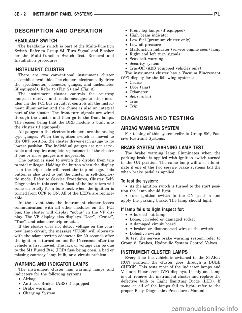
DESCRIPTION AND OPERATION
HEADLAMP SWITCH
The headlamp switch is part of the Multi-Function
Switch. Refer to Group 8J, Turn Signal and Flasher
for the Multi-Function Switch Test, Removal and
Installation procedures.
INSTRUMENT CLUSTER
There are two conventional instrument cluster
assemblies available. The clusters electronically drive
the speedometer, odometer, gauges, and tachometer
(if equipped). Refer to (Fig. 2) and (Fig. 3).
The instrument cluster controls the courtesy
lamps, it receives and sends messages to other mod-
ules via the PCI bus circuit, it controls all the instru-
ment illumination and the chime is also an integral
part of the cluster. The front turn signals are wired
through the cluster and then go to the front lamps.
The reason being that the DRL module is built into
the cluster (if equipped).
All gauges in the electronic clusters are the analog
type gauges. When the ignition switch is moved to
the OFF position, the cluster drives each gauge to its
lowest position. The individual gauges are not servi-
cable and require complete replacement of the cluster
if one or more gauges are inoperable.
One button is used to switch the display from trip
to total mileage. Holding the button when the display
is in the trip mode will reset the trip mileage. This
button is also used to put the cluster in self-diagnos-
tic mode. Refer to Service Procedures, Cluster Self-
Diagnostics in this section. Most of the indicators will
come on briefly for a bulb heck when the ignition is
turned from OFF to ON. All of the LED's are replace-
able.
In the event that the instrument cluster looses
communication with all other modules on the PCI
bus, the cluster will display ªnobusº in the VF dis-
play. The VF display also displays ªDoorº, ªCruiseº,
ªTracº, and odometer trip or total.
If the cluster does not detect voltage on the cour-
tesy lamp circuit, the message ªFUSEº will alternate
with the odometer/trip odometer for 30 seconds after
the ignition is turned on and for 15 seconds after the
vehicle is first moved. The lack of voltage can be due
to the M1 Fused B(+) (IOD) fuse being open, a bad or
missing courtesy lamp bulb, or a circuit problem.
WARNING AND INDICATOR LAMPS
The instrument cluster has warning lamps and
indicators for the following systems:
²Airbag
²Anti-lock Brakes (ABS) if equipped
²Brake warning
²Charging System²Front fog lamps (if equipped)
²High beam indicator
²Low fuel (premium cluster only)
²Low oil pressure
²Malfunction indicator (service engine soon) lamp
²Right and left turn signals
²Seat belt warning
²Security system
²Trac-Off (ABS equipped vehicles only)
The instrument cluster has a Vacuum Fluorescent
(VF) display for the following systems:
²Cruise
²Door (ajar)
²Odometer
²Set (cruise)
²Trac
²Trip
DIAGNOSIS AND TESTING
AIRBAG WARNING SYSTEM
For testing of this system refer to Group 8M, Pas-
sive Restraint Systems.
BRAKE SYSTEM WARNING LAMP TEST
The brake warning lamp illuminates when the
parking brake is applied with ignition switch turned
to the ON position. The same lamp will also illumi-
nate if one of the two service brake systems fail the
when brake pedal is applied.
To test the system:
²As the ignition switch is turned to the start posi-
tion the lamp should light.
²Turn ignition switch to the ON position and
apply the parking brake. The lamp should light.
If lamp fails to light inspect for:
²A burned out lamp
²Loose, corroded or damaged socket
²A damaged circuit board
²A broken or disconnected wire at the switch
²Defective switch
To test the service brake warning system, refer to
Group 5, Brakes, Hydraulic System Control Valves.
INSTRUMENT CLUSTER LAMPS
Every time the vehicle is switched to the START/
RUN position, the cluster goes through a BULB
CHECK. This tests most of the indicator lamps and
Vacuum Fluorescent (VF) displays. If only one lamp
is out, remove the instrument cluster and replace the
defective bulb or Light Emitting Diode (LED). If
some or all of the lamps fail to light, refer to the
proper Body Diagnostics Procedures Manual.
8E - 2 INSTRUMENT PANEL SYSTEMSPL
Page 250 of 1285
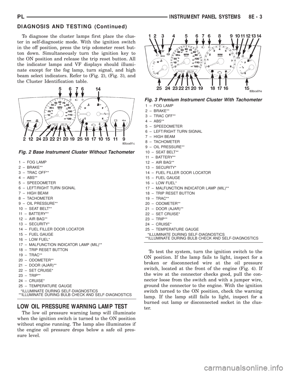
To diagnose the cluster lamps first place the clus-
ter in self-diagnostic mode. With the ignition switch
in the off position, press the trip odometer reset but-
ton down. Simultaneously turn the ignition key to
the ON position and release the trip reset button. All
the indicator lamps and VF displays should illumi-
nate except for the fog lamp, turn signal, and high
beam select indicators. Refer to (Fig. 2), (Fig. 3), and
the Cluster Identification table.
1 ± FOG LAMP
2 ± BRAKE**
3 ± TRAC OFF**
4 ± ABS**
5 ± SPEEDOMETER
6 ± LEFT/RIGHT TURN SIGNAL
7 ± HIGH BEAM
8 ± TACHOMETER
9 ± OIL PRESSURE**
10 ± SEAT BELT**
11 ± BATTERY**
12 ± AIR BAG**
13 ± SECURITY*
14 ± FUEL FILLER DOOR LOCATOR
15 ± FUEL GAUGE
16 ± LOW FUEL*
17 ± MALFUNCTION INDICATOR LAMP (MIL)**
18 ± TRIP RESET BUTTON
19 ± TRAC**
20 ± ODOMETER**
21 ± DOOR (AJAR)**
22 ± SET CRUISE*
23 ± TRIP**
24 ± CRUISE*
25 ± TEMPERATURE GAUGE
*ILLUMINATE DURING SELF-DIAGNOSTICS
**ILLUMINATE DURING BULB CHECK AND SELF-DIAGNOSTICS
LOW OIL PRESSURE WARNING LAMP TEST
The low oil pressure warning lamp will illuminate
when the ignition switch is turned to the ON position
without engine running. The lamp also illuminates if
the engine oil pressure drops below a safe oil pres-
sure level.To test the system, turn the ignition switch to the
ON position. If the lamp fails to light, inspect for a
broken or disconnected wire at the oil pressure
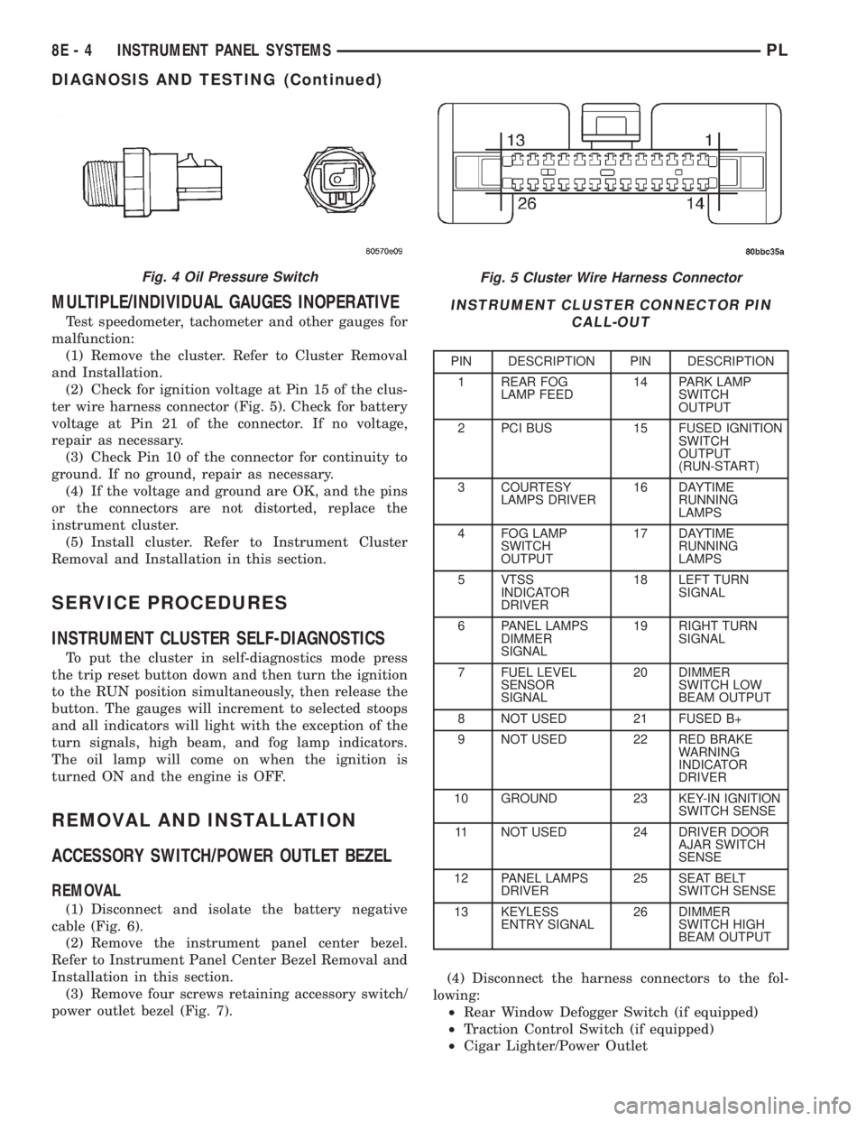
switch, located at the front of the engine (Fig. 4). If
the wire at the connector checks good, pull the con-
nector loose from the switch and with a jumper wire,
ground the connector to the engine. With the ignition
switch turned to the ON position, check the warning
lamp. If the lamp still fails to light, inspect for a
burned out lamp or disconnected socket in the clus-
ter.
Fig. 2 Base Instrument Cluster Without Tachometer
Fig. 3 Premium Instrument Cluster With Tachometer
1 ± FOG LAMP
2 ± BRAKE**
3 ± TRAC OFF**
4 ± ABS**
5 ± SPEEDOMETER
6 ± LEFT/RIGHT TURN SIGNAL
7 ± HIGH BEAM
8 ± TACHOMETER
9 ± OIL PRESSURE**
10 ± SEAT BELT**
11 ± BATTERY**
12 ± AIR BAG**
13 ± SECURITY*
14 ± FUEL FILLER DOOR LOCATOR
15 ± FUEL GAUGE
16 ± LOW FUEL*
17 ± MALFUNCTION INDICATOR LAMP (MIL)**
18 ± TRIP RESET BUTTON
19 ± TRAC**
20 ± ODOMETER**
21 ± DOOR (AJAR)**
22 ± SET CRUISE*
23 ± TRIP**
24 ± CRUISE*
25 ± TEMPERATURE GAUGE
*ILLUMINATE DURING SELF-DIAGNOSTICS
**ILLUMINATE DURING BULB CHECK AND SELF-DIAGNOSTICS
PLINSTRUMENT PANEL SYSTEMS 8E - 3
DIAGNOSIS AND TESTING (Continued)
Page 251 of 1285
MULTIPLE/INDIVIDUAL GAUGES INOPERATIVE
Test speedometer, tachometer and other gauges for
malfunction:
(1) Remove the cluster. Refer to Cluster Removal
and Installation.
(2) Check for ignition voltage at Pin 15 of the clus-
ter wire harness connector (Fig. 5). Check for battery
voltage at Pin 21 of the connector. If no voltage,
repair as necessary.
(3) Check Pin 10 of the connector for continuity to
ground. If no ground, repair as necessary.
(4) If the voltage and ground are OK, and the pins
or the connectors are not distorted, replace the
instrument cluster.
(5) Install cluster. Refer to Instrument Cluster
Removal and Installation in this section.
SERVICE PROCEDURES
INSTRUMENT CLUSTER SELF-DIAGNOSTICS
To put the cluster in self-diagnostics mode press
the trip reset button down and then turn the ignition
to the RUN position simultaneously, then release the
button. The gauges will increment to selected stoops
and all indicators will light with the exception of the
turn signals, high beam, and fog lamp indicators.
The oil lamp will come on when the ignition is
turned ON and the engine is OFF.
REMOVAL AND INSTALLATION
ACCESSORY SWITCH/POWER OUTLET BEZEL
REMOVAL
(1) Disconnect and isolate the battery negative
cable (Fig. 6).
(2) Remove the instrument panel center bezel.
Refer to Instrument Panel Center Bezel Removal and
Installation in this section.
(3) Remove four screws retaining accessory switch/
power outlet bezel (Fig. 7).(4) Disconnect the harness connectors to the fol-
lowing:
²Rear Window Defogger Switch (if equipped)
²Traction Control Switch (if equipped)
²Cigar Lighter/Power Outlet
Fig. 5 Cluster Wire Harness Connector
INSTRUMENT CLUSTER CONNECTOR PIN
CALL-OUT
PIN DESCRIPTION PIN DESCRIPTION
1 REAR FOG
LAMP FEED14 PARK LAMP
SWITCH
OUTPUT
2 PCI BUS 15 FUSED IGNITION
SWITCH
OUTPUT
(RUN-START)
3 COURTESY
LAMPS DRIVER16 DAYTIME
RUNNING
LAMPS
4 FOG LAMP
SWITCH
OUTPUT17 DAYTIME
RUNNING
LAMPS
5 VTSS
INDICATOR
DRIVER18 LEFT TURN
SIGNAL
6 PANEL LAMPS
DIMMER
SIGNAL19 RIGHT TURN
SIGNAL
7 FUEL LEVEL
SENSOR
SIGNAL20 DIMMER
SWITCH LOW
BEAM OUTPUT
8 NOT USED 21 FUSED B+
9 NOT USED 22 RED BRAKE
WARNING
INDICATOR
DRIVER
10 GROUND 23 KEY-IN IGNITION
SWITCH SENSE
11 NOT USED 24 DRIVER DOOR
AJAR SWITCH
SENSE
12 PANEL LAMPS
DRIVER25 SEAT BELT
SWITCH SENSE
13 KEYLESS
ENTRY SIGNAL26 DIMMER
SWITCH HIGH
BEAM OUTPUT
Fig. 4 Oil Pressure Switch
8E - 4 INSTRUMENT PANEL SYSTEMSPL
DIAGNOSIS AND TESTING (Continued)