2000 DODGE NEON check oil
[x] Cancel search: check oilPage 742 of 1285
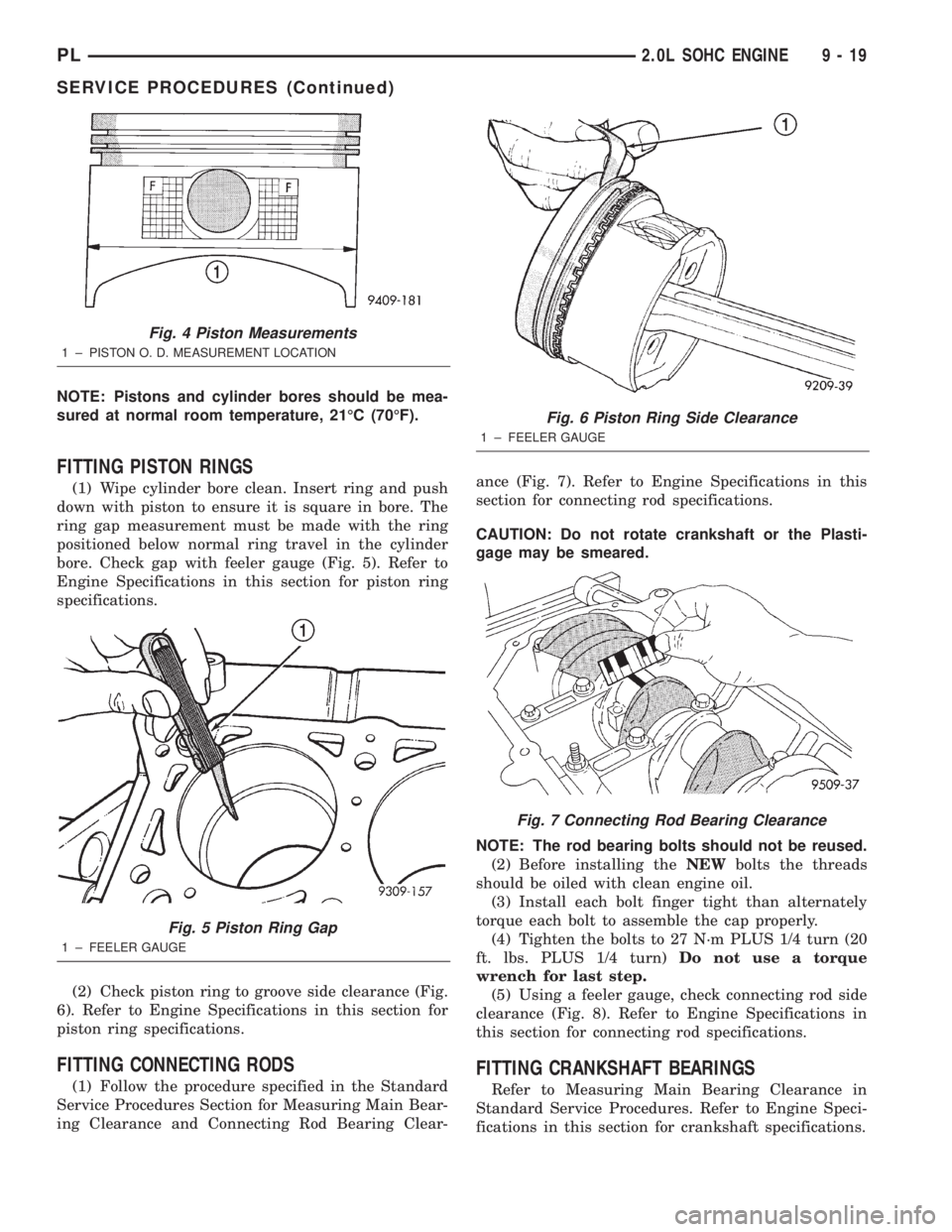
NOTE: Pistons and cylinder bores should be mea-
sured at normal room temperature, 21ÉC (70ÉF).
FITTING PISTON RINGS
(1) Wipe cylinder bore clean. Insert ring and push
down with piston to ensure it is square in bore. The
ring gap measurement must be made with the ring
positioned below normal ring travel in the cylinder
bore. Check gap with feeler gauge (Fig. 5). Refer to
Engine Specifications in this section for piston ring
specifications.
(2) Check piston ring to groove side clearance (Fig.
6). Refer to Engine Specifications in this section for
piston ring specifications.
FITTING CONNECTING RODS
(1) Follow the procedure specified in the Standard
Service Procedures Section for Measuring Main Bear-
ing Clearance and Connecting Rod Bearing Clear-ance (Fig. 7). Refer to Engine Specifications in this
section for connecting rod specifications.
CAUTION: Do not rotate crankshaft or the Plasti-
gage may be smeared.
NOTE: The rod bearing bolts should not be reused.
(2) Before installing theNEWbolts the threads
should be oiled with clean engine oil.
(3) Install each bolt finger tight than alternately
torque each bolt to assemble the cap properly.
(4) Tighten the bolts to 27 N´m PLUS 1/4 turn (20
ft. lbs. PLUS 1/4 turn)Do not use a torque
wrench for last step.
(5) Using a feeler gauge, check connecting rod side
clearance (Fig. 8). Refer to Engine Specifications in
this section for connecting rod specifications.
FITTING CRANKSHAFT BEARINGS
Refer to Measuring Main Bearing Clearance in
Standard Service Procedures. Refer to Engine Speci-
fications in this section for crankshaft specifications.
Fig. 4 Piston Measurements
1 ± PISTON O. D. MEASUREMENT LOCATION
Fig. 5 Piston Ring Gap
1 ± FEELER GAUGE
Fig. 6 Piston Ring Side Clearance
1 ± FEELER GAUGE
Fig. 7 Connecting Rod Bearing Clearance
PL2.0L SOHC ENGINE 9 - 19
SERVICE PROCEDURES (Continued)
Page 752 of 1285
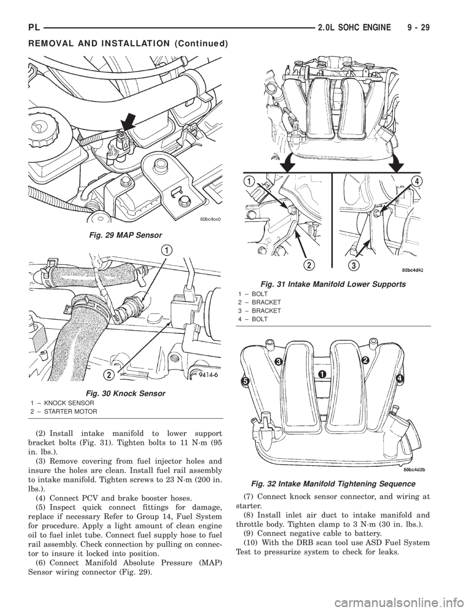
(2) Install intake manifold to lower support
bracket bolts (Fig. 31). Tighten bolts to 11 N´m (95
in. lbs.).
(3) Remove covering from fuel injector holes and
insure the holes are clean. Install fuel rail assembly
to intake manifold. Tighten screws to 23 N´m (200 in.
lbs.).
(4) Connect PCV and brake booster hoses.
(5) Inspect quick connect fittings for damage,
replace if necessary Refer to Group 14, Fuel System
for procedure. Apply a light amount of clean engine
oil to fuel inlet tube. Connect fuel supply hose to fuel
rail assembly. Check connection by pulling on connec-
tor to insure it locked into position.
(6) Connect Manifold Absolute Pressure (MAP)
Sensor wiring connector (Fig. 29).(7) Connect knock sensor connector, and wiring at
starter.
(8) Install inlet air duct to intake manifold and
throttle body. Tighten clamp to 3 N´m (30 in. lbs.).
(9) Connect negative cable to battery.
(10) With the DRB scan tool use ASD Fuel System
Test to pressurize system to check for leaks.
Fig. 29 MAP Sensor
Fig. 30 Knock Sensor
1 ± KNOCK SENSOR
2 ± STARTER MOTOR
Fig. 31 Intake Manifold Lower Supports
1 ± BOLT
2 ± BRACKET
3 ± BRACKET
4 ± BOLT
Fig. 32 Intake Manifold Tightening Sequence
PL2.0L SOHC ENGINE 9 - 29
REMOVAL AND INSTALLATION (Continued)
Page 757 of 1285
INSPECT CYLINDER HEAD FOR THE FOLLOWING:
NOTE:
²Check oil feed holes for blockage.
²Inspect cylinder head camshaft bearings for
wear, Refer to Cylinder Head, Inspection and Clean-
ing.
²Check camshaft bearing journals for scratches
and worn areas. If light scratches are present, they
may be removed with 400 grit sand paper. If deep
scratches are present, replace the camshaft and
check the cylinder head for damage. Replace the
cylinder head if worn or damaged. Check the lobes
for pitting and wear. If the lobes show signs of
wear, check the corresponding rocker arm roller for
wear or damage. Replace rocker arm/hydraulic lash
adjuster if worn or damaged. If lobes show signs of
pitting on the nose, flank or base circle; replace the
camshaft.
INSTALLATION
(1) Lubricate the camshaft journals with oil and
install camshaftwithoutrocker arm assemblies
installed.
(2) Install camshaft target magnet into the end of
the camshaft. Tighten mounting screw to 3.4 N´m (30
in. lbs.).
(3) Install camshaft position sensor and tighten
mounting screws to 9 N´m (80 in. lbs.).
(4) Measure camshaft end play using the following
procedure:
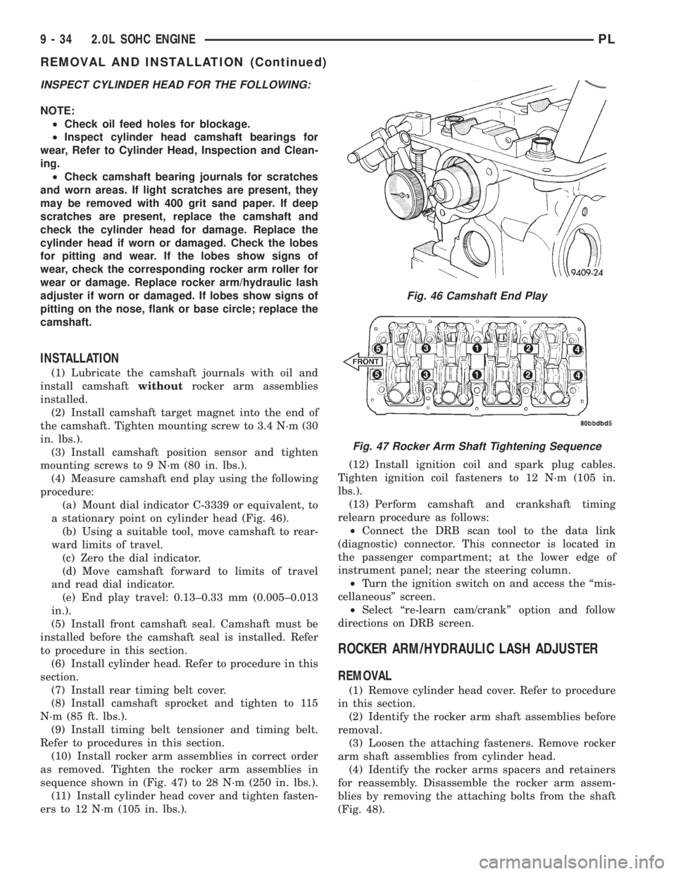
(a) Mount dial indicator C-3339 or equivalent, to
a stationary point on cylinder head (Fig. 46).
(b) Using a suitable tool, move camshaft to rear-
ward limits of travel.
(c) Zero the dial indicator.
(d) Move camshaft forward to limits of travel
and read dial indicator.
(e) End play travel: 0.13±0.33 mm (0.005±0.013
in.).
(5) Install front camshaft seal. Camshaft must be
installed before the camshaft seal is installed. Refer
to procedure in this section.
(6) Install cylinder head. Refer to procedure in this
section.
(7) Install rear timing belt cover.
(8) Install camshaft sprocket and tighten to 115
N´m (85 ft. lbs.).
(9) Install timing belt tensioner and timing belt.
Refer to procedures in this section.
(10) Install rocker arm assemblies in correct order
as removed. Tighten the rocker arm assemblies in
sequence shown in (Fig. 47) to 28 N´m (250 in. lbs.).
(11) Install cylinder head cover and tighten fasten-
ers to 12 N´m (105 in. lbs.).(12) Install ignition coil and spark plug cables.
Tighten ignition coil fasteners to 12 N´m (105 in.
lbs.).
(13) Perform camshaft and crankshaft timing
relearn procedure as follows:
²Connect the DRB scan tool to the data link
(diagnostic) connector. This connector is located in
the passenger compartment; at the lower edge of
instrument panel; near the steering column.
²Turn the ignition switch on and access the ªmis-
cellaneousº screen.
²Select ªre-learn cam/crankº option and follow
directions on DRB screen.
ROCKER ARM/HYDRAULIC LASH ADJUSTER
REMOVAL
(1) Remove cylinder head cover. Refer to procedure
in this section.
(2) Identify the rocker arm shaft assemblies before
removal.
(3) Loosen the attaching fasteners. Remove rocker
arm shaft assemblies from cylinder head.
(4) Identify the rocker arms spacers and retainers
for reassembly. Disassemble the rocker arm assem-
blies by removing the attaching bolts from the shaft
(Fig. 48).
Fig. 46 Camshaft End Play
Fig. 47 Rocker Arm Shaft Tightening Sequence
9 - 34 2.0L SOHC ENGINEPL
REMOVAL AND INSTALLATION (Continued)
Page 758 of 1285
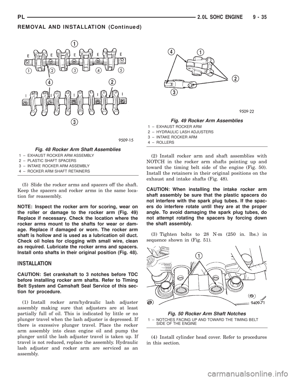
(5) Slide the rocker arms and spacers off the shaft.
Keep the spacers and rocker arms in the same loca-
tion for reassembly.
NOTE: Inspect the rocker arm for scoring, wear on
the roller or damage to the rocker arm (Fig. 49)
Replace if necessary. Check the location where the
rocker arms mount to the shafts for wear or dam-
age. Replace if damaged or worn. The rocker arm
shaft is hollow and is used as a lubrication oil duct.
Check oil holes for clogging with small wire, clean
as required. Lubricate the rocker arms and spacers.
Install onto shafts in their original position (Fig. 48).
INSTALLATION
CAUTION: Set crankshaft to 3 notches before TDC
before installing rocker arm shafts. Refer to Timing
Belt System and Camshaft Seal Service of this sec-
tion for procedure.
(1) Install rocker arm/hydraulic lash adjuster
assembly making sure that adjusters are at least
partially full of oil. This is indicated by little or no
plunger travel when the lash adjuster is depressed. If
there is excessive plunger travel. Place the rocker
arm assembly into clean engine oil and pump the
plunger until the lash adjuster travel is taken up. If
travel is not reduced, replace the assembly. Hydraulic
lash adjuster and rocker arm are serviced as an
assembly.(2) Install rocker arm and shaft assemblies with
NOTCH in the rocker arm shafts pointing up and
toward the timing belt side of the engine (Fig. 50).
Install the retainers in their original positions on the
exhaust and intake shafts (Fig. 48).
CAUTION: When installing the intake rocker arm
shaft assembly be sure that the plastic spacers do
not interfere with the spark plug tubes. If the spac-
ers do interfere rotate until they are at the proper
angle. To avoid damaging the spark plug tubes, do
not attempt rotating the spacers by forcing down
the shaft assembly.
(3) Tighten bolts to 28 N´m (250 in. lbs.) in
sequence shown in (Fig. 51).
(4) Install cylinder head cover. Refer to procedures
in this section.
Fig. 48 Rocker Arm Shaft Assemblies
1 ± EXHAUST ROCKER ARM ASSEMBLY
2 ± PLASTIC SHAFT SPACERS
3 ± INTAKE ROCKER ARM ASSEMBLY
4 ± ROCKER ARM SHAFT RETAINERS
Fig. 49 Rocker Arm Assemblies
1 ± EXHAUST ROCKER ARM
2 ± HYDRAULIC LASH ADJUSTERS
3 ± INTAKE ROCKER ARM
4 ± ROLLERS
Fig. 50 Rocker Arm Shaft Notches
1 ± NOTCHES FACING UP AND TOWARD THE TIMING BELT
SIDE OF THE ENGINE
PL2.0L SOHC ENGINE 9 - 35
REMOVAL AND INSTALLATION (Continued)
Page 762 of 1285
(2) Apply MopartGasket Sealant (aerosol can) to
both sides of the new cylinder head gasket.
(3) Position a new cylinder head gasket on the
locating dowels.
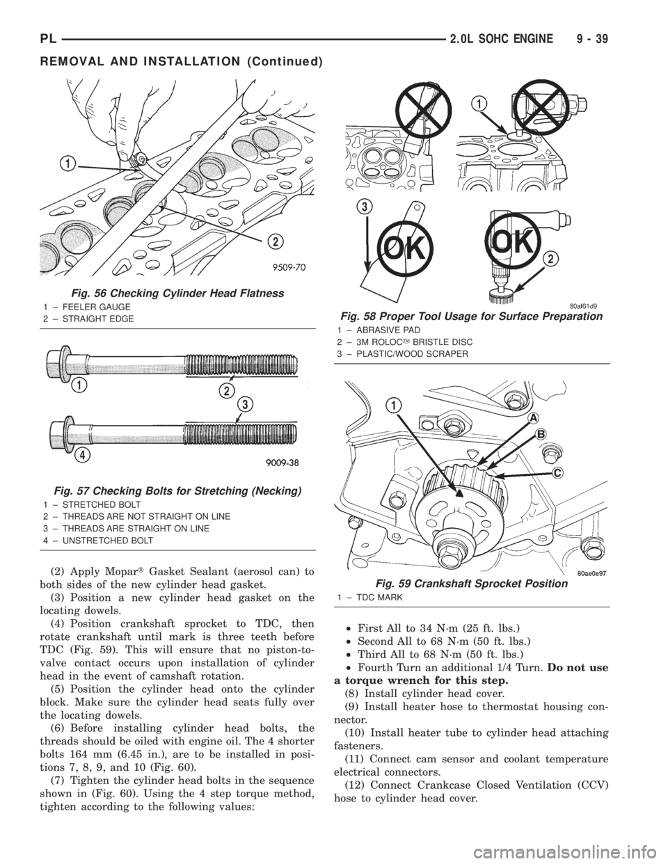
(4) Position crankshaft sprocket to TDC, then
rotate crankshaft until mark is three teeth before
TDC (Fig. 59). This will ensure that no piston-to-
valve contact occurs upon installation of cylinder
head in the event of camshaft rotation.
(5) Position the cylinder head onto the cylinder
block. Make sure the cylinder head seats fully over
the locating dowels.
(6) Before installing cylinder head bolts, the
threads should be oiled with engine oil. The 4 shorter
bolts 164 mm (6.45 in.), are to be installed in posi-
tions 7, 8, 9, and 10 (Fig. 60).
(7) Tighten the cylinder head bolts in the sequence
shown in (Fig. 60). Using the 4 step torque method,
tighten according to the following values:²First All to 34 N´m (25 ft. lbs.)
²Second All to 68 N´m (50 ft. lbs.)
²Third All to 68 N´m (50 ft. lbs.)
²Fourth Turn an additional 1/4 Turn.Do not use
a torque wrench for this step.
(8) Install cylinder head cover.
(9) Install heater hose to thermostat housing con-
nector.
(10) Install heater tube to cylinder head attaching
fasteners.
(11) Connect cam sensor and coolant temperature
electrical connectors.
(12) Connect Crankcase Closed Ventilation (CCV)
hose to cylinder head cover.
Fig. 56 Checking Cylinder Head Flatness
1 ± FEELER GAUGE
2 ± STRAIGHT EDGE
Fig. 57 Checking Bolts for Stretching (Necking)
1 ± STRETCHED BOLT
2 ± THREADS ARE NOT STRAIGHT ON LINE
3 ± THREADS ARE STRAIGHT ON LINE
4 ± UNSTRETCHED BOLT
Fig. 58 Proper Tool Usage for Surface Preparation
1 ± ABRASIVE PAD
2 ± 3M ROLOCYBRISTLE DISC
3 ± PLASTIC/WOOD SCRAPER
Fig. 59 Crankshaft Sprocket Position
1 ± TDC MARK
PL2.0L SOHC ENGINE 9 - 39
REMOVAL AND INSTALLATION (Continued)
Page 766 of 1285
TIMING BELT
CHECKING BELT TIMINGÐCOVER INSTALLED
²Remove number one spark plug.
²Using a dial indicator, set number one cylinder
to TDC on the compression stroke.
²Remove the access plug from the outer timing
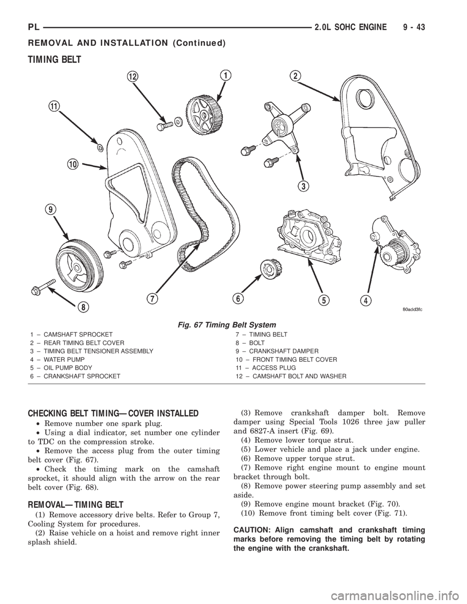
belt cover (Fig. 67).
²Check the timing mark on the camshaft
sprocket, it should align with the arrow on the rear
belt cover (Fig. 68).
REMOVALÐTIMING BELT
(1) Remove accessory drive belts. Refer to Group 7,
Cooling System for procedures.
(2) Raise vehicle on a hoist and remove right inner
splash shield.(3) Remove crankshaft damper bolt. Remove
damper using Special Tools 1026 three jaw puller
and 6827-A insert (Fig. 69).
(4) Remove lower torque strut.
(5) Lower vehicle and place a jack under engine.
(6) Remove upper torque strut.
(7) Remove right engine mount to engine mount
bracket through bolt.
(8) Remove power steering pump assembly and set
aside.
(9) Remove engine mount bracket (Fig. 70).
(10) Remove front timing belt cover (Fig. 71).
CAUTION: Align camshaft and crankshaft timing
marks before removing the timing belt by rotating
the engine with the crankshaft.
Fig. 67 Timing Belt System
1 ± CAMSHAFT SPROCKET
2 ± REAR TIMING BELT COVER
3 ± TIMING BELT TENSIONER ASSEMBLY
4 ± WATER PUMP
5 ± OIL PUMP BODY
6 ± CRANKSHAFT SPROCKET7 ± TIMING BELT
8 ± BOLT
9 ± CRANKSHAFT DAMPER
10 ± FRONT TIMING BELT COVER
11 ± ACCESS PLUG
12 ± CAMSHAFT BOLT AND WASHER
PL2.0L SOHC ENGINE 9 - 43
REMOVAL AND INSTALLATION (Continued)
Page 768 of 1285
CAMSHAFT AND CRANKSHAFT TIMING
PROCEDURE AND BELT INSTALLATION
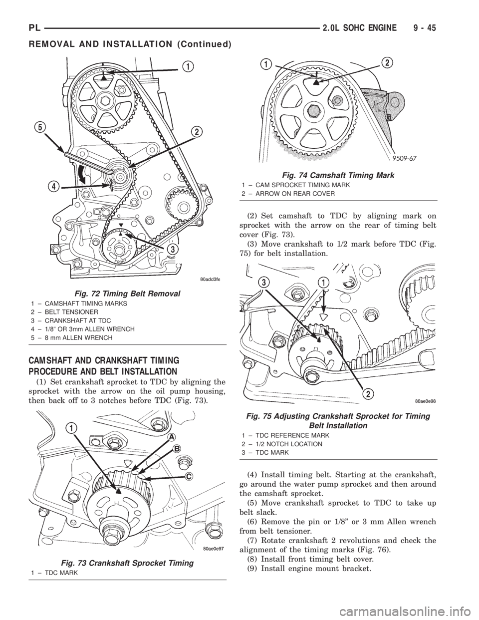
(1) Set crankshaft sprocket to TDC by aligning the
sprocket with the arrow on the oil pump housing,
then back off to 3 notches before TDC (Fig. 73).(2) Set camshaft to TDC by aligning mark on
sprocket with the arrow on the rear of timing belt
cover (Fig. 73).
(3) Move crankshaft to 1/2 mark before TDC (Fig.
75) for belt installation.
(4) Install timing belt. Starting at the crankshaft,
go around the water pump sprocket and then around
the camshaft sprocket.
(5) Move crankshaft sprocket to TDC to take up
belt slack.
(6) Remove the pin or 1/8º or 3 mm Allen wrench
from belt tensioner.
(7) Rotate crankshaft 2 revolutions and check the
alignment of the timing marks (Fig. 76).
(8) Install front timing belt cover.
(9) Install engine mount bracket.
Fig. 72 Timing Belt Removal
1 ± CAMSHAFT TIMING MARKS
2 ± BELT TENSIONER
3 ± CRANKSHAFT AT TDC
4 ± 1/8º OR 3mm ALLEN WRENCH
5 ± 8 mm ALLEN WRENCH
Fig. 73 Crankshaft Sprocket Timing
1 ± TDC MARK
Fig. 74 Camshaft Timing Mark
1 ± CAM SPROCKET TIMING MARK
2 ± ARROW ON REAR COVER
Fig. 75 Adjusting Crankshaft Sprocket for Timing
Belt Installation
1 ± TDC REFERENCE MARK
2 ± 1/2 NOTCH LOCATION
3 ± TDC MARK
PL2.0L SOHC ENGINE 9 - 45
REMOVAL AND INSTALLATION (Continued)
Page 776 of 1285
NOTE: Do not reuse connecting rod bolts.
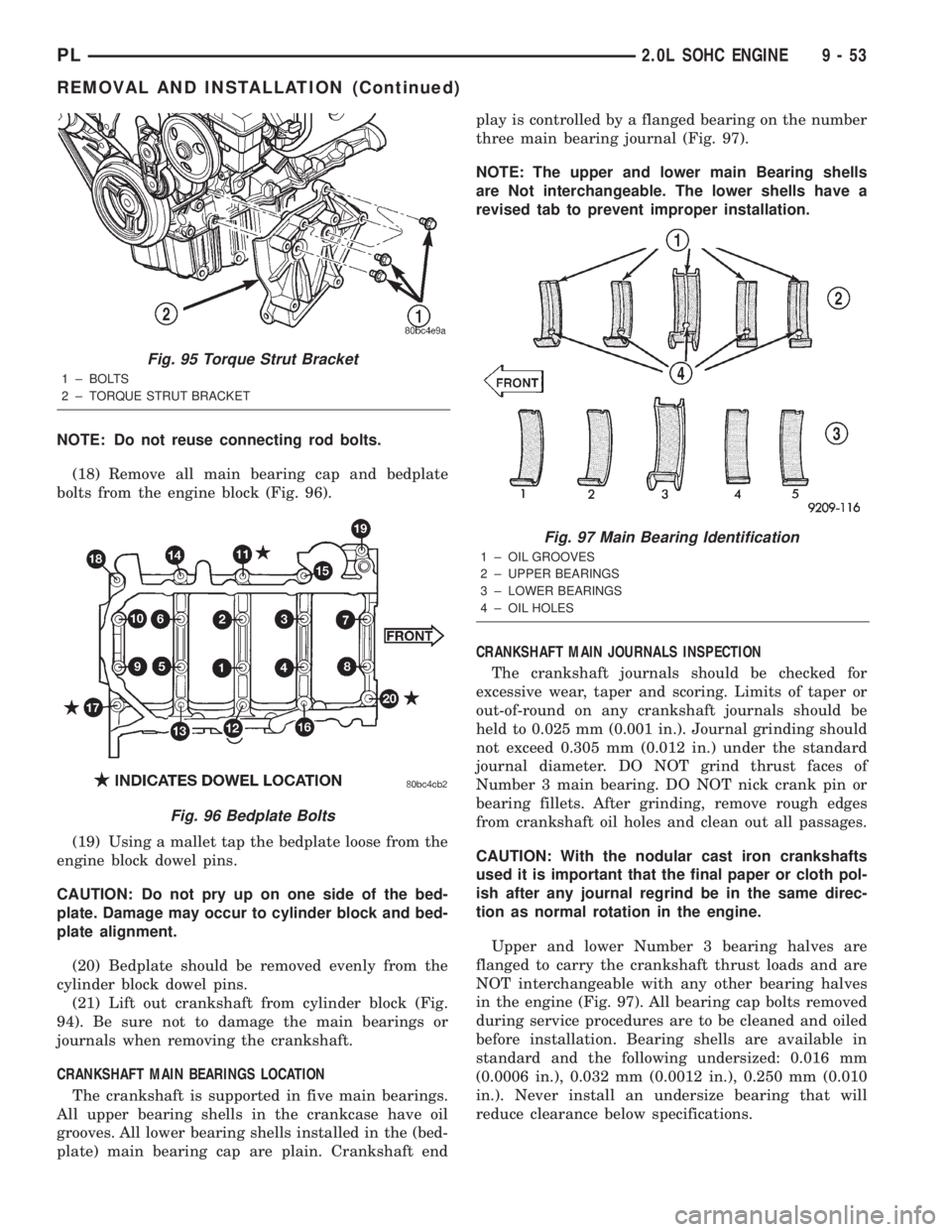
(18) Remove all main bearing cap and bedplate
bolts from the engine block (Fig. 96).
(19) Using a mallet tap the bedplate loose from the
engine block dowel pins.
CAUTION: Do not pry up on one side of the bed-
plate. Damage may occur to cylinder block and bed-
plate alignment.
(20) Bedplate should be removed evenly from the
cylinder block dowel pins.
(21) Lift out crankshaft from cylinder block (Fig.
94). Be sure not to damage the main bearings or
journals when removing the crankshaft.
CRANKSHAFT MAIN BEARINGS LOCATION
The crankshaft is supported in five main bearings.
All upper bearing shells in the crankcase have oil
grooves. All lower bearing shells installed in the (bed-
plate) main bearing cap are plain. Crankshaft endplay is controlled by a flanged bearing on the number
three main bearing journal (Fig. 97).
NOTE: The upper and lower main Bearing shells
are Not interchangeable. The lower shells have a
revised tab to prevent improper installation.
CRANKSHAFT MAIN JOURNALS INSPECTION
The crankshaft journals should be checked for
excessive wear, taper and scoring. Limits of taper or
out-of-round on any crankshaft journals should be
held to 0.025 mm (0.001 in.). Journal grinding should
not exceed 0.305 mm (0.012 in.) under the standard
journal diameter. DO NOT grind thrust faces of
Number 3 main bearing. DO NOT nick crank pin or
bearing fillets. After grinding, remove rough edges
from crankshaft oil holes and clean out all passages.
CAUTION: With the nodular cast iron crankshafts
used it is important that the final paper or cloth pol-
ish after any journal regrind be in the same direc-
tion as normal rotation in the engine.
Upper and lower Number 3 bearing halves are
flanged to carry the crankshaft thrust loads and are
NOT interchangeable with any other bearing halves
in the engine (Fig. 97). All bearing cap bolts removed
during service procedures are to be cleaned and oiled
before installation. Bearing shells are available in
standard and the following undersized: 0.016 mm
(0.0006 in.), 0.032 mm (0.0012 in.), 0.250 mm (0.010
in.). Never install an undersize bearing that will
reduce clearance below specifications.
Fig. 95 Torque Strut Bracket
1 ± BOLTS
2 ± TORQUE STRUT BRACKET
Fig. 96 Bedplate Bolts
Fig. 97 Main Bearing Identification
1 ± OIL GROOVES
2 ± UPPER BEARINGS
3 ± LOWER BEARINGS
4 ± OIL HOLES
PL2.0L SOHC ENGINE 9 - 53
REMOVAL AND INSTALLATION (Continued)