2000 DODGE NEON check oil
[x] Cancel search: check oilPage 35 of 1285
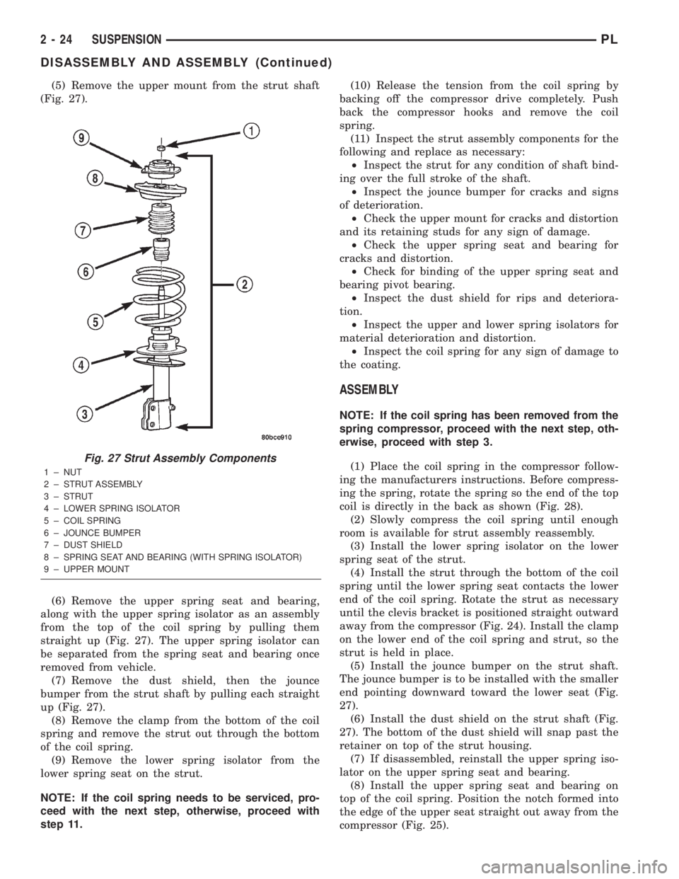
(5) Remove the upper mount from the strut shaft
(Fig. 27).
(6) Remove the upper spring seat and bearing,
along with the upper spring isolator as an assembly
from the top of the coil spring by pulling them
straight up (Fig. 27). The upper spring isolator can
be separated from the spring seat and bearing once
removed from vehicle.
(7) Remove the dust shield, then the jounce
bumper from the strut shaft by pulling each straight
up (Fig. 27).
(8) Remove the clamp from the bottom of the coil
spring and remove the strut out through the bottom
of the coil spring.
(9) Remove the lower spring isolator from the
lower spring seat on the strut.
NOTE: If the coil spring needs to be serviced, pro-
ceed with the next step, otherwise, proceed with
step 11.(10) Release the tension from the coil spring by
backing off the compressor drive completely. Push
back the compressor hooks and remove the coil
spring.
(11) Inspect the strut assembly components for the
following and replace as necessary:
²Inspect the strut for any condition of shaft bind-
ing over the full stroke of the shaft.
²Inspect the jounce bumper for cracks and signs
of deterioration.
²Check the upper mount for cracks and distortion
and its retaining studs for any sign of damage.
²Check the upper spring seat and bearing for
cracks and distortion.
²Check for binding of the upper spring seat and
bearing pivot bearing.
²Inspect the dust shield for rips and deteriora-
tion.
²Inspect the upper and lower spring isolators for
material deterioration and distortion.
²Inspect the coil spring for any sign of damage to
the coating.
ASSEMBLY
NOTE: If the coil spring has been removed from the
spring compressor, proceed with the next step, oth-
erwise, proceed with step 3.
(1) Place the coil spring in the compressor follow-
ing the manufacturers instructions. Before compress-
ing the spring, rotate the spring so the end of the top
coil is directly in the back as shown (Fig. 28).
(2) Slowly compress the coil spring until enough
room is available for strut assembly reassembly.
(3) Install the lower spring isolator on the lower
spring seat of the strut.
(4) Install the strut through the bottom of the coil
spring until the lower spring seat contacts the lower
end of the coil spring. Rotate the strut as necessary
until the clevis bracket is positioned straight outward
away from the compressor (Fig. 24). Install the clamp
on the lower end of the coil spring and strut, so the
strut is held in place.
(5) Install the jounce bumper on the strut shaft.
The jounce bumper is to be installed with the smaller
end pointing downward toward the lower seat (Fig.
27).
(6) Install the dust shield on the strut shaft (Fig.
27). The bottom of the dust shield will snap past the
retainer on top of the strut housing.
(7) If disassembled, reinstall the upper spring iso-
lator on the upper spring seat and bearing.
(8) Install the upper spring seat and bearing on
top of the coil spring. Position the notch formed into
the edge of the upper seat straight out away from the
compressor (Fig. 25).
Fig. 27 Strut Assembly Components
1 ± NUT
2 ± STRUT ASSEMBLY
3 ± STRUT
4 ± LOWER SPRING ISOLATOR
5 ± COIL SPRING
6 ± JOUNCE BUMPER
7 ± DUST SHIELD
8 ± SPRING SEAT AND BEARING (WITH SPRING ISOLATOR)
9 ± UPPER MOUNT
2 - 24 SUSPENSIONPL
DISASSEMBLY AND ASSEMBLY (Continued)
Page 60 of 1285
²Check the upper mount for cracks and distortion
and its retaining studs for any sign of damage.
²Inspect the dust shield for rips and deteriora-
tion.
²Inspect the upper and lower spring isolators for
material deterioration and distortion.
²Inspect the coil spring for any sign of damage to
the coating.
ASSEMBLY
NOTE: If the coil spring has been removed from the
spring compressor, proceed with the next step, oth-
erwise, proceed with step 3.
(1) Place the coil spring in the compressor follow-
ing the manufacturers instructions. Before compress-
ing the spring, rotate the spring to the position
determined in the note prior to step 9 in disassembly.
(2) Slowly compress the coil spring until enough
room is available for strut assembly reassembly.
(3) Install the lower spring isolator on the lower
spring seat of the strut matching the step built intothe isolator with the step in the lower spring seat on
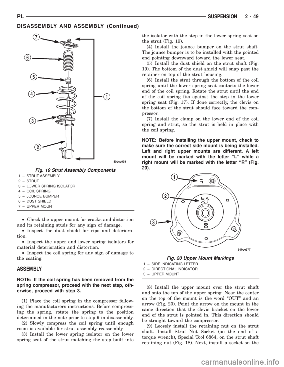
the strut (Fig. 19).
(4) Install the jounce bumper on the strut shaft.
The jounce bumper is to be installed with the pointed
end pointing downward toward the lower seat.
(5) Install the dust shield on the strut shaft (Fig.
19). The bottom of the dust shield will snap past the
retainer on top of the strut housing.
(6) Install the strut through the bottom of the coil
spring until the lower spring seat contacts the lower
end of the coil spring. Rotate the strut until the end
of the coil spring fits against the step in the lower
spring seat (Fig. 17). If done correctly, the clevis on
the bottom of the strut should face toward the com-
pressor.
(7) Install the clamp on the lower end of the coil
spring and strut, so the strut is held in place with
the coil spring.
NOTE: Before installing the upper mount, check to
make sure the correct side mount is being installed.
Left and right upper mounts are different. A left
mount will be marked with the letter ªLº while a
right mount will be marked with the letter ªRº (Fig.
20).
(8) Install the upper mount over the strut shaft
and onto the top of the upper spring. Near the center
on the top of the mount is the word ªOUTº and an
arrow (Fig. 20). Point the arrow on the mount in the
same direction that the clevis bracket on the lower
end of the strut is pointed in. This direction should
be straight toward the compressor.
(9) Loosely install the retaining nut on the strut
shaft. Install Strut Nut Socket (on the end of a
torque wrench), Special Tool 6864, on the strut shaft
retaining nut (Fig. 18). Next, install a socket on the
Fig. 19 Strut Assembly Components
1 ± STRUT ASSEMBLY
2 ± STRUT
3 ± LOWER SPRING ISOLATOR
4 ± COIL SPRING
5 ± JOUNCE BUMPER
6 ± DUST SHIELD
7 ± UPPER MOUNT
Fig. 20 Upper Mount Markings
1 ± SIDE INDICATING LETTER
2 ± DIRECTIONAL INDICATOR
3 ± UPPER MOUNT
PLSUSPENSION 2 - 49
DISASSEMBLY AND ASSEMBLY (Continued)
Page 96 of 1285
following this procedure. If the inlet gauge pressure
overshoots its target pressure when the pedal is
depressed, release the brake pedal, relieving the
pressure in the system, before reapplying the pedal
to reach the target pressure at the inlet gauge. This
is necessary to get an accurate reading of the outlet
pressure.
(10) Once inlet pressure has been achieved, check
the pressure reading on the proportioning valve out-
let gauge. If the proportioning valve outlet pressure
does not agree with value shown in the table, replace
the proportioning valve. If proportioning valve is
within pressure specifications, the valve is good and
does not require replacement.(11)Reinstall the brake holding tool on the brake
pedal and remove the test equipment from the vehicle.
(12) Remove the tools from the proportioning
valve.
(13) Install the proportioning valve in the master
cylinder and hand tighten until the proportioning
valve is fully installed and its O-ring seal is seated
into the master cylinder. Torque the proportioning
valve to 40 N´m (30 ft. lbs.).
(14) Install the brake tube on the proportioning
valve. Torque the tube nut to 17 N´m (145 in. lbs.).
(15) Bleed the affected brake line. See BASE
BRAKE BLEEDING in this section of this service
manual group.
BRAKE PROPORTIONING VALVE APPLICATIONS AND PRESSURE SPECIFICATIONS
Sales
CodeBrake System Type Split Point Slope IdentificationInlet
PressureOutlet Pressure
BRA 14º Disc/Drum 300 psi 0.34 Black Band 1000 psi 550-650 psi
BRD 14º Disc/Disc 400 psi 0.43 Bar Code Band 1000 psi 600-700 psi
BRAKE FLUID CONTAMINATION
Indications of fluid contamination are swollen or
deteriorated rubber parts. Swelling indicates the
presence of petroleum in the brake fluid.
To test for contamination, put a small amount of
drained brake fluid in clear glass jar. If the fluid sep-
arates into layers, there is mineral oil or other fluid
contamination of the brake fluid.
If the brake fluid is contaminated, drain and thor-
oughly flush the brake system. Replace all the rubber
parts or components containing rubber coming into
contact with the brake fluid including: the master
cylinder; proportioning valves; caliper seals; wheel
cylinder seals; ABS hydraulic control unit; and all
hydraulic fluid hoses.
SERVICE PROCEDURES
BRAKE FLUID LEVEL CHECKING
Brake fluid level should be checked a minimum of
twice a year.
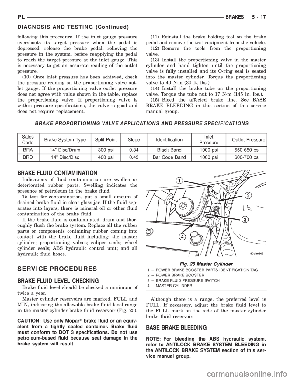
Master cylinder reservoirs are marked, FULL and
MIN, indicating the allowable brake fluid level range
in the master cylinder brake fluid reservoir (Fig. 25).
CAUTION: Use only MoparTbrake fluid or an equiv-
alent from a tightly sealed container. Brake fluid
must conform to DOT 3 specifications. Do not use
petroleum-based fluid because seal damage in the
brake system will result.Although there is a range, the preferred level is
FULL. If necessary, adjust the brake fluid level to
the FULL mark on the side of the master cylinder
brake fluid reservoir.
BASE BRAKE BLEEDING
NOTE: For bleeding the ABS hydraulic system,
refer to ANTILOCK BRAKE SYSTEM BLEEDING in
the ANTILOCK BRAKE SYSTEM section of this ser-
vice manual group.
Fig. 25 Master Cylinder
1 ± POWER BRAKE BOOSTER PARTS IDENTIFICATION TAG
2 ± POWER BRAKE BOOSTER
3 ± BRAKE FLUID PRESSURE SWITCH
4 ± MASTER CYLINDER
PLBRAKES 5 - 17
DIAGNOSIS AND TESTING (Continued)
Page 138 of 1285
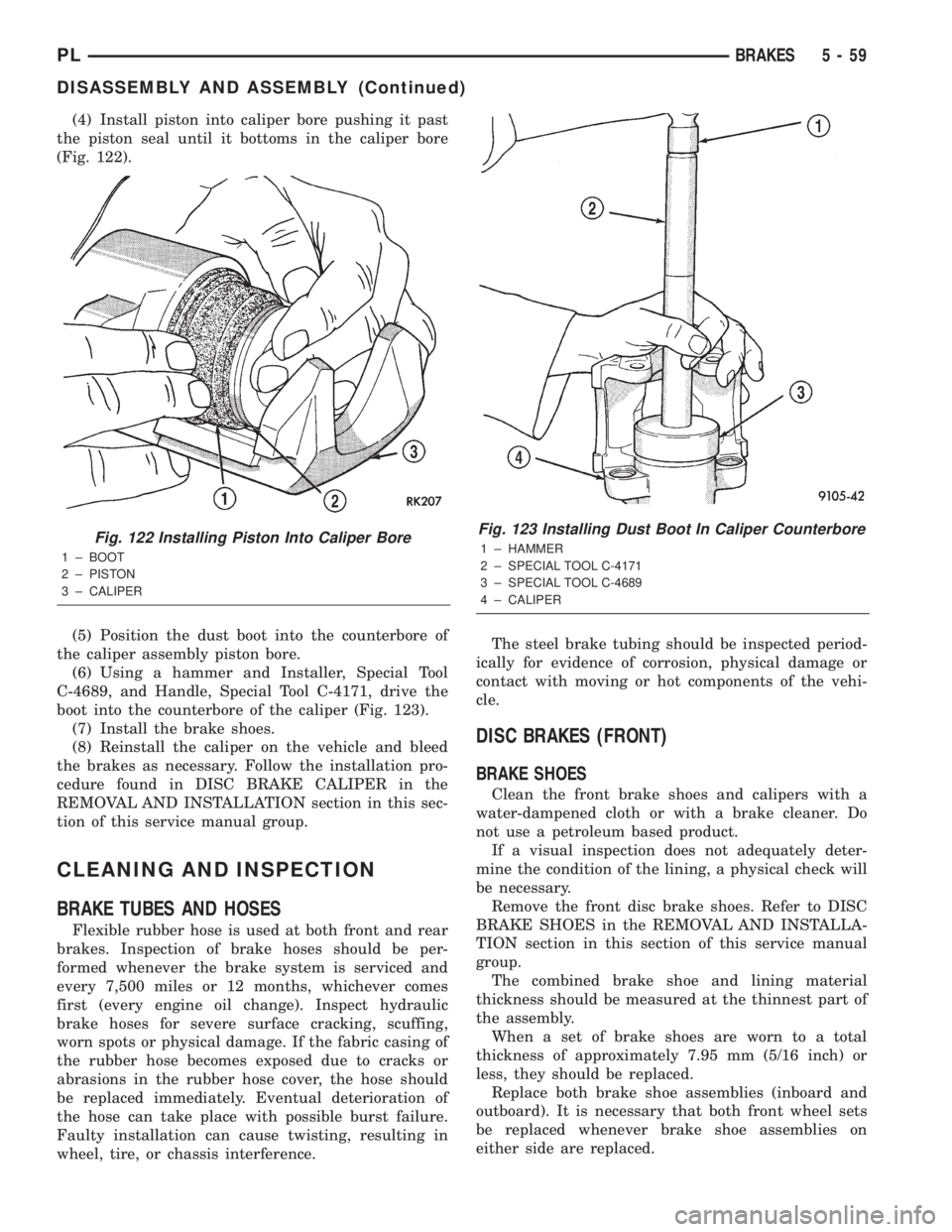
(4) Install piston into caliper bore pushing it past
the piston seal until it bottoms in the caliper bore
(Fig. 122).
(5) Position the dust boot into the counterbore of
the caliper assembly piston bore.
(6) Using a hammer and Installer, Special Tool
C-4689, and Handle, Special Tool C-4171, drive the
boot into the counterbore of the caliper (Fig. 123).
(7) Install the brake shoes.
(8) Reinstall the caliper on the vehicle and bleed
the brakes as necessary. Follow the installation pro-
cedure found in DISC BRAKE CALIPER in the
REMOVAL AND INSTALLATION section in this sec-
tion of this service manual group.
CLEANING AND INSPECTION
BRAKE TUBES AND HOSES
Flexible rubber hose is used at both front and rear
brakes. Inspection of brake hoses should be per-
formed whenever the brake system is serviced and
every 7,500 miles or 12 months, whichever comes
first (every engine oil change). Inspect hydraulic
brake hoses for severe surface cracking, scuffing,
worn spots or physical damage. If the fabric casing of
the rubber hose becomes exposed due to cracks or
abrasions in the rubber hose cover, the hose should
be replaced immediately. Eventual deterioration of
the hose can take place with possible burst failure.
Faulty installation can cause twisting, resulting in
wheel, tire, or chassis interference.The steel brake tubing should be inspected period-
ically for evidence of corrosion, physical damage or
contact with moving or hot components of the vehi-
cle.
DISC BRAKES (FRONT)
BRAKE SHOES
Clean the front brake shoes and calipers with a
water-dampened cloth or with a brake cleaner. Do
not use a petroleum based product.
If a visual inspection does not adequately deter-
mine the condition of the lining, a physical check will
be necessary.
Remove the front disc brake shoes. Refer to DISC
BRAKE SHOES in the REMOVAL AND INSTALLA-
TION section in this section of this service manual
group.
The combined brake shoe and lining material
thickness should be measured at the thinnest part of
the assembly.
When a set of brake shoes are worn to a total
thickness of approximately 7.95 mm (5/16 inch) or
less, they should be replaced.
Replace both brake shoe assemblies (inboard and
outboard). It is necessary that both front wheel sets
be replaced whenever brake shoe assemblies on
either side are replaced.
Fig. 122 Installing Piston Into Caliper Bore
1 ± BOOT
2 ± PISTON
3 ± CALIPER
Fig. 123 Installing Dust Boot In Caliper Counterbore
1 ± HAMMER
2 ± SPECIAL TOOL C-4171
3 ± SPECIAL TOOL C-4689
4 ± CALIPER
PLBRAKES 5 - 59
DISASSEMBLY AND ASSEMBLY (Continued)
Page 139 of 1285
If the brake shoe assemblies do not require
replacement, reinstall the assemblies making sure
each brake shoe is returned to the original position.
Refer to DISC BRAKE SHOES in the REMOVAL
AND INSTALLATION section in this section of this
service manual group.
CALIPER INSPECTION
Check for brake fluid leaks in and around the boot
area. Check for any ruptures, brittleness or damage
to the piston dust boot. If the boot is damaged, or a
fluid leak is visible, disassemble the caliper assembly
and install a new seal and boot, and a piston if it is
scored. Refer to DISC BRAKE CALIPER in the DIS-
ASSEMBLY AND ASSEMBLY section in this section
of this service manual group.
Check the guide pin dust boots to determine if they
are in good condition. Replace if they are damaged,
dry, or found to be brittle. Refer to DISC BRAKE
CALIPER in the DISASSEMBLY AND ASSEMBLY
section in this section of this service manual group.
DISC BRAKES (REAR)
BRAKE SHOES
Clean the rear brake shoes and calipers with a
water-dampened cloth or with a brake cleaner. Do
not use a petroleum based product.
If a visual inspection does not adequately deter-
mine the condition of the lining, a physical check will
be necessary.
Remove the rear disc brake shoes. Refer to DISC
BRAKE SHOES in the REMOVAL AND INSTALLA-
TION section in this section of this service manual
group.
The combined brake shoe and lining material
thickness should be measured at the thinnest part of
the assembly.
When a set of brake shoes are worn to a total
thickness of approximately 7.0 mm (9/32 inch) or
less, they should be replaced.
Replace both brake shoe assemblies (inboard and
outboard). It is necessary that both front wheel sets
be replaced whenever brake shoe assemblies on
either side are replaced.
If the brake shoe assemblies do not require
replacement, reinstall the assemblies making sure
each brake shoe is returned to the original position.
Refer to DISC BRAKE SHOES in the REMOVAL
AND INSTALLATION section in this section of this
service manual group.
CALIPER INSPECTION
Check for brake fluid leaks in and around the boot
area. Check for any ruptures, brittleness or damage
to the piston dust boot. If the boot is damaged, or afluid leak is visible, disassemble the caliper assembly
and install a new seal and boot, and a piston if it is
scored. Refer to DISC BRAKE CALIPER in the DIS-
ASSEMBLY AND ASSEMBLY section in this section
of this service manual group.
Check the guide pin dust boots to determine if they
are in good condition. Replace if they are damaged,
dry, or found to be brittle. Refer to DISC BRAKE
CALIPER in the DISASSEMBLY AND ASSEMBLY
section in this section of this service manual group.
DRUM BRAKES (REAR)
BRAKE SHOES
Clean the rear brake shoes and springs with a
water-dampened cloth or with a brake cleaner. Do
not use a petroleum based product.
Rear brake shoe lining should show contact across
the entire width of the lining and also from the heel
to the toe of the lining. Replace the shoes if noted
otherwise.
Brake shoes with lack of contact at the toe or heel
of the brake shoe lining may be improperly ground.
Clean and inspect the brake support plate and
shoe adjuster screw. Apply a thin coat of Mopart
Multi-Purpose Lubricant or equivalent to the threads
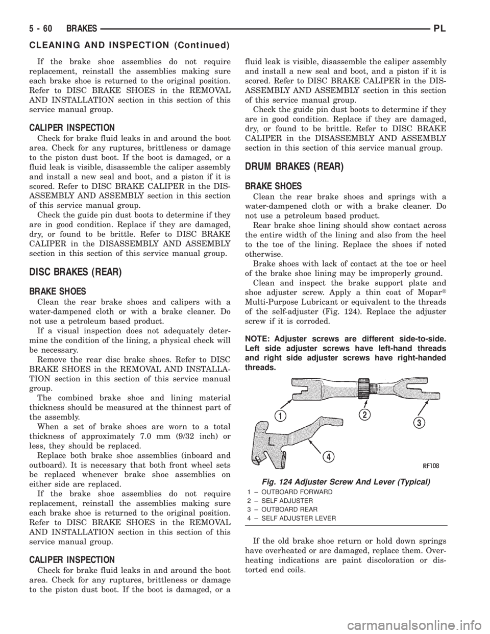
of the self-adjuster (Fig. 124). Replace the adjuster
screw if it is corroded.
NOTE: Adjuster screws are different side-to-side.
Left side adjuster screws have left-hand threads
and right side adjuster screws have right-handed
threads.
If the old brake shoe return or hold down springs
have overheated or are damaged, replace them. Over-
heating indications are paint discoloration or dis-
torted end coils.
Fig. 124 Adjuster Screw And Lever (Typical)
1 ± OUTBOARD FORWARD
2 ± SELF ADJUSTER
3 ± OUTBOARD REAR
4 ± SELF ADJUSTER LEVER
5 - 60 BRAKESPL
CLEANING AND INSPECTION (Continued)
Page 155 of 1285
junction block. A label on the underside of the PDC
cover identifies the locations of the ABS fuses.
(2) Inspect the 25-way electrical connector at the
CAB for damaged, spread, or backed-out wiring ter-
minals. Verify that the 25-way connector is fully
inserted in the socket of the CAB. Be sure that wires
are not stretched tight or pulled out of the connector.
(3) Verify that all the wheel speed sensor connec-
tions are secure.
(4) Look for poor mating of connector halves or ter-
minals not fully seated in the connector body.
(5)
Check for improperly formed or damaged termi-
nals. All connector terminals in a suspect circuit should
be carefully reformed to increase contact tension.
(6) Look for poor terminal-to-wire connections.
This requires removing the terminal from the connec-
tor body to inspect it.
(7) Verify pin presence in the connector assembly
(8) Check for proper ground connections. Check all
ground connections for signs of corrosion, loose fas-
teners, or other potential defects. Refer to the wiring
diagrams for ground locations.
(9) Look for problems with the main power sources
of the vehicle. Inspect the battery, generator, ignition
circuits and other related relays and fuses.
If a visual check does not find the cause of the
problem, operate the car in an attempt to duplicate
the condition and record any trouble codes.
Most failures of the ABS disable the ABS function
for the entire ignition cycle even if the fault clears
before key-off. There are some failure conditions,
however, that allow ABS operation to resume during
the ignition cycle in which the trouble occurred even
if the trouble conditions are no longer present.
The following trouble conditions may result in
intermittent illumination of the amber ABS warning
lamp.
²Low system voltage. If Low System Voltage is
detected by the CAB, the CAB will turn on the ABS
Warning Lamp until normal system voltage is
achieved. Once normal voltage is seen at the CAB,
normal operation resumes.
²High system voltage. If high system voltage is
detected by the CAB, the CAB will turn on the
Amber ABS Warning Lamp until normal system volt-
age is achieved. Once normal voltage is again
detected by the CAB, normal ABS operation resumes.
Additional possible causes that may result in the
illumination of the amber ABS warning lamp are as
follows:
²Any condition that interrupts electrical current
to the CAB may cause the amber ABS warning lamp
to turn on intermittently.
²If PCI communication between the body control-
ler and the CAB is interrupted, the body controller
can turn on the amber ABS warning lamp.
TONE WHEEL
Tone wheels can cause erratic wheel speed sensor
signals. Inspect tone wheels for the following possible
causes:
²missing, chipped, or broken teeth
²contact with the wheel speed sensor
²wheel speed sensor to tone wheel alignment
²wheel speed sensor to tone wheel clearance
²excessive tone wheel runout
²tone wheel loose on its mounting surface
If a front tone wheel is found to need replacement,
the drive shaft must be replaced. No attempt should
be made to replace just the tone wheel. Refer to the
DIFFERENTIAL AND DRIVELINE group in this
service manual for removal and installation.
If a rear tone wheel is found to need replacement,
the rear hub and bearing must be replaced. No
attempt should be made to replace just the tone
wheel. Refer to the SUSPENSION group in this ser-
vice manual for removal and installation.
If wheel speed sensor to tone wheel contact is evi-
dent, determine the cause and correct it before
replacing the wheel speed sensor or tone wheel.
Check the gap between the speed sensor head and
the tone wheel to ensure it is within specifications.
Refer to SPECIFICATIONS in this section of the ser-
vice manual for the minimum and maximum wheel
speed sensor to tone wheel clearance.
Excessive wheel speed sensor runout can cause
erratic wheel speed sensor signals. Refer to SPECI-
FICATIONS in this section of the service manual for
the maximum allowed tone wheel runout. If tone
wheel runout is excessive, determine if it is caused
by a defect in the driveshaft assembly or hub and
bearing. Replace as necessary.
Tone wheels are pressed onto their mounting sur-
faces and should not rotate independently from the
mounting surface. Replacement of the front drive-
shaft or rear hub and bearing is necessary.
BRAKE FLUID CONTAMINATION
Indications of fluid contamination are swollen or
deteriorated rubber parts. Swelling indicates the
presence of petroleum in the brake fluid.
To test for contamination, put a small amount of
drained brake fluid in clear glass jar. If the fluid sep-
arates into layers, there is mineral oil or other fluid
contamination of the brake fluid.
If the brake fluid is contaminated, drain and thor-
oughly flush the brake system. Replace all the rubber
parts or components containing rubber coming into
contact with the brake fluid including: the master
cylinder; proportioning valves; caliper seals; wheel
cylinder seals; ABS hydraulic control unit; and all
hydraulic fluid hoses.
5 - 76 BRAKESPL
DIAGNOSIS AND TESTING (Continued)
Page 168 of 1285
SERVICE DIAGNOSISÐCLUTCH GRAB/CHATTER
CONDITION POSSIBLE CAUSES CORRECTION
CLUTCH DISC
FACING COVERED
WITH OIL OR
GREASEOil leak at engine rear main or transaxle
input shaft sealCorrect leak and replace modular clutch
assembly
Too much grease applied to splines of disc
and input shaftApply lighter coating of grease to splines
NO FAULT FOUND
WITH CLUTCH
COMPONENTSProblem actually related to suspension or
driveline componentFurther diagnosis required. Check
engine/transmission mounts, suspension
attaching parts and other driveline
components as needed.
Engine related problems Check EFI and ignition systems
PARTIAL
ENGAGEMENT OF
CLUTCH DISCClutch cover, spring, or release fingers
bent, distorted (rough handling, improper
assembly)Replace modular clutch assembly
Clutch disc damaged or distorted Replace modular clutch assembly
Clutch misalignment Check alignment and runout of flywheel,
disc, or cover. Check clutch housing to
engine dowels and dowel holes for damage.
Correct as necessary.
SERVICE DIAGNOSISÐCLUTCH SLIPS
CONDITION POSSIBLE CAUSES CORRECTION
DISC FACING
WORN OUTNormal wear. Replace modular clutch assembly.
Driver frequently rides (slips) clutch, results
in rapid wear overheating.Replace modular clutch assembly
Insufficient clutch cover diaphragm spring
tensionReplace modular clutch assembly
CLUTCH DISC
FACING
CONTAMINATED
WITH OIL OR
GREASELeak at rear main oil seal or transaxle input
shaft sealReplace leaking seals. Replace modular
clutch assembly.
Excessive amount of grease applied to
input shaft splinesApply less grease to input shaft. Replace
modular clutch assembly
Road splash, water entering housing Seal housing. Inspect clutch assembly.
CLUTCH IS
RUNNING
PARTIALLY
DISENGAGEDRelease bearing sticking or binding, does
not return to normal running position.Verify that bearing is actually binding. Then,
replace bearing and transmission front
bearing retainer if sleeve surface is
damaged.
Cable self-adjuster mechanism sticking or
binding causing high preloadVerify that self-adjuster is free to move
PLCLUTCH 6 - 3
DIAGNOSIS AND TESTING (Continued)
Page 170 of 1285
DRIVE PLATE MISALIGNMENT
Common causes of misalignment are:
²Heat warping
²Mounting drive plate on a dirty crankshaft
flange
²Incorrect bolt tightening
²Improper seating on the crankshaft shoulder
²Loose crankshaft bolts
Clean the crankshaft flange before mounting the
drive plate. Dirt and grease on the flange surface
may misalign the flywheel, causing excessive runout.
Use new bolts when mounting drive plate to crank-
shaft. Tighten drive plate bolts to specified torque
only. Over-tightening can distort the drive plate hub
causing excessive runout.
CLUTCH CHATTER COMPLAINTS
For all clutch chatter complaints, do the following:
(1) Check for loose, misaligned, or broken engine
and transmission mounts. If present, they should be
corrected at this time. Test vehicle for chatter. If
chatter is gone, there is no need to go any further. If
chatter persists:
(2) Check to see if clutch cable routing is correct
and operates smoothly.
(3) Check for loose connections in drive train. Cor-
rect any problems and determine if clutch chatter
complaints have been satisfied. If not:
(4) Remove transaxle. See Group 21, Manual Tran-
saxle for procedure.
(5) Check to see if the release bearing is sticky or
binding. Replace bearing, if needed.
(6) Check linkage for excessive wear on the pivot
stud and fork fingers. Replace all worn parts.
(7) Check clutch assembly for contamination (dirt,
oil). Replace clutch assembly, if required.
(8) Check to see if the clutch disc hub splines are
damaged. Replace with new clutch assembly, if nec-
essary.
(9) Check input shaft splines for damage. Replace,
if necessary.
(10) Check for uneven wear on clutch fingers.
(11) Check for broken clutch cover diaphragm
spring fingers. Replace with new clutch assembly, if
necessary.
CLASH±INTO±REVERSE COMPLAINTS
Certain NV T350 (A-578) manual transaxles are
equipped with a reverse brake. It prevents clash
when shifting into reverse, but only if the vehicle is
not moving. See Group 21, Transaxle for further
diagnosis.
(1) Depress clutch pedal to floor and hold. After
three seconds, shift to reverse. If clash is present,
clutch has excessive spin time, and the reverse brake
may not be functioning.(2) Remove transaxle. See Group 21, Manual Tran-
saxle for procedure.
(3) Check the input shaft spline, clutch disc
splines, and release bearing for dry rust. If present,
clean rust off and apply a light coat of bearing grease
to the input shaft splines. Apply grease on the input
shaft splines only where the clutch disc slides. Verify
that the clutch disc slides freely along the input shaft
spline.
(4) Check to see if the clutch disc hub splines are
damaged, and replace with new clutch assembly if
required.
(5) Check the input shaft for damaged splines.
Replace as necessary.
(6) Check for broken clutch cover diaphragm
spring fingers.
(7) Install clutch assembly and transaxle.
CLUTCH INTERLOCK/UPSTOP SWITCH
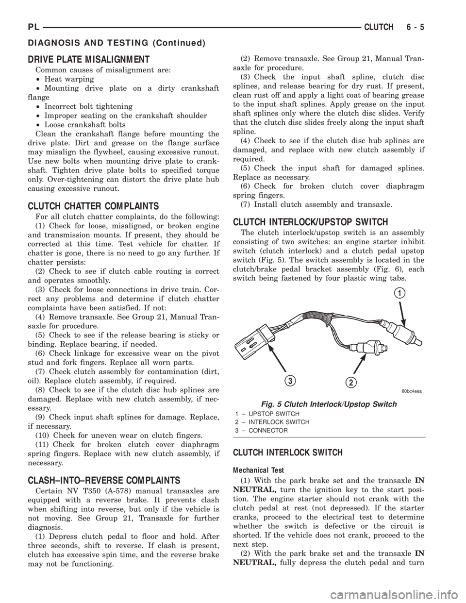
The clutch interlock/upstop switch is an assembly
consisting of two switches: an engine starter inhibit
switch (clutch interlock) and a clutch pedal upstop
switch (Fig. 5). The switch assembly is located in the
clutch/brake pedal bracket assembly (Fig. 6), each
switch being fastened by four plastic wing tabs.
CLUTCH INTERLOCK SWITCH
Mechanical Test
(1) With the park brake set and the transaxleIN
NEUTRAL,turn the ignition key to the start posi-
tion. The engine starter should not crank with the
clutch pedal at rest (not depressed). If the starter
cranks, proceed to the electrical test to determine
whether the switch is defective or the circuit is
shorted. If the vehicle does not crank, proceed to the
next step.
(2) With the park brake set and the transaxleIN
NEUTRAL,fully depress the clutch pedal and turn
Fig. 5 Clutch Interlock/Upstop Switch
1 ± UPSTOP SWITCH
2 ± INTERLOCK SWITCH
3 ± CONNECTOR
PLCLUTCH 6 - 5
DIAGNOSIS AND TESTING (Continued)