2000 DODGE NEON wheel alignment
[x] Cancel search: wheel alignmentPage 878 of 1285
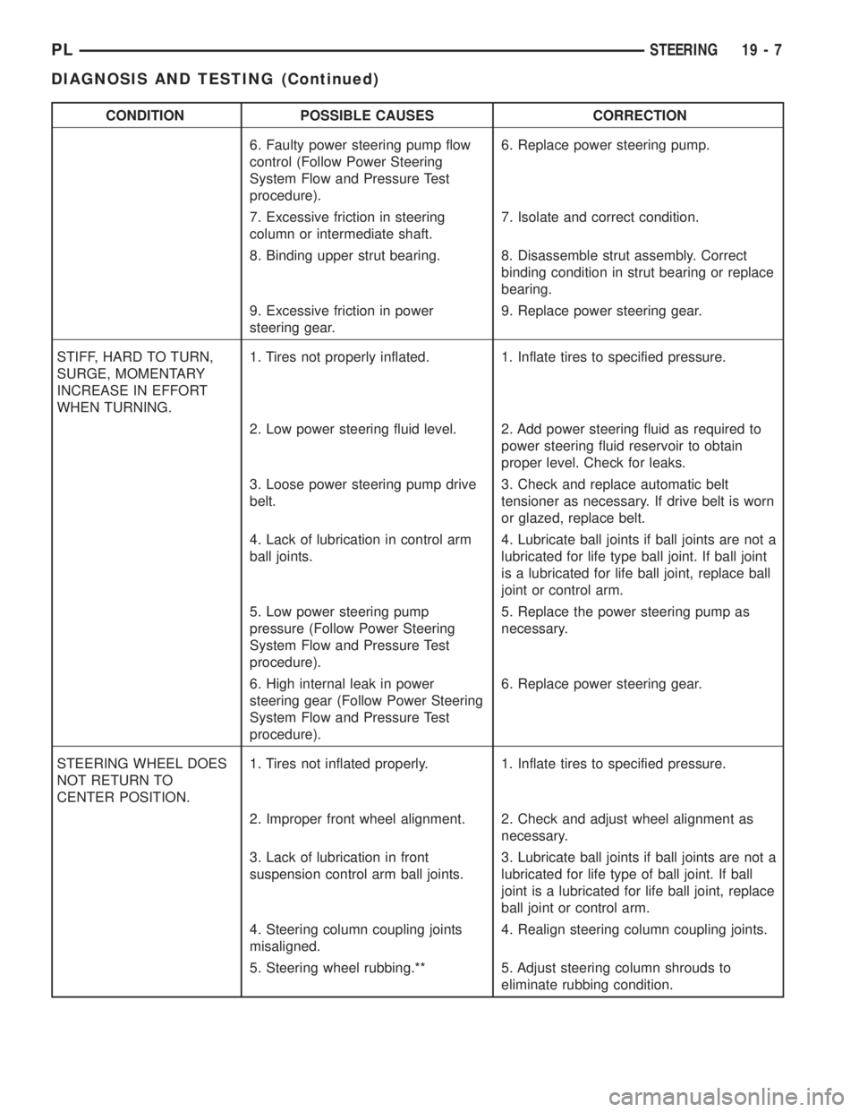
CONDITION POSSIBLE CAUSES CORRECTION
6. Faulty power steering pump flow
control (Follow Power Steering
System Flow and Pressure Test
procedure).6. Replace power steering pump.
7. Excessive friction in steering
column or intermediate shaft.7. Isolate and correct condition.
8. Binding upper strut bearing. 8. Disassemble strut assembly. Correct
binding condition in strut bearing or replace
bearing.
9. Excessive friction in power
steering gear.9. Replace power steering gear.
STIFF, HARD TO TURN,
SURGE, MOMENTARY
INCREASE IN EFFORT
WHEN TURNING.1. Tires not properly inflated. 1. Inflate tires to specified pressure.
2. Low power steering fluid level. 2. Add power steering fluid as required to
power steering fluid reservoir to obtain
proper level. Check for leaks.
3. Loose power steering pump drive
belt.3. Check and replace automatic belt
tensioner as necessary. If drive belt is worn
or glazed, replace belt.
4. Lack of lubrication in control arm
ball joints.4. Lubricate ball joints if ball joints are not a
lubricated for life type ball joint. If ball joint
is a lubricated for life ball joint, replace ball
joint or control arm.
5. Low power steering pump
pressure (Follow Power Steering
System Flow and Pressure Test
procedure).5. Replace the power steering pump as
necessary.
6. High internal leak in power
steering gear (Follow Power Steering
System Flow and Pressure Test
procedure).6. Replace power steering gear.
STEERING WHEEL DOES
NOT RETURN TO
CENTER POSITION.1. Tires not inflated properly. 1. Inflate tires to specified pressure.
2. Improper front wheel alignment. 2. Check and adjust wheel alignment as
necessary.
3. Lack of lubrication in front
suspension control arm ball joints.3. Lubricate ball joints if ball joints are not a
lubricated for life type of ball joint. If ball
joint is a lubricated for life ball joint, replace
ball joint or control arm.
4. Steering column coupling joints
misaligned.4. Realign steering column coupling joints.
5. Steering wheel rubbing.** 5. Adjust steering column shrouds to
eliminate rubbing condition.
PLSTEERING 19 - 7
DIAGNOSIS AND TESTING (Continued)
Page 895 of 1285
(13) If the vehicle is equipped with a power steer-
ing fluid cooler, remove the two screws securing the
cooler to the front suspension crossmember. They are
located behind the cooler and can be accessed from
above. Allow the cooler to hang out of the way.
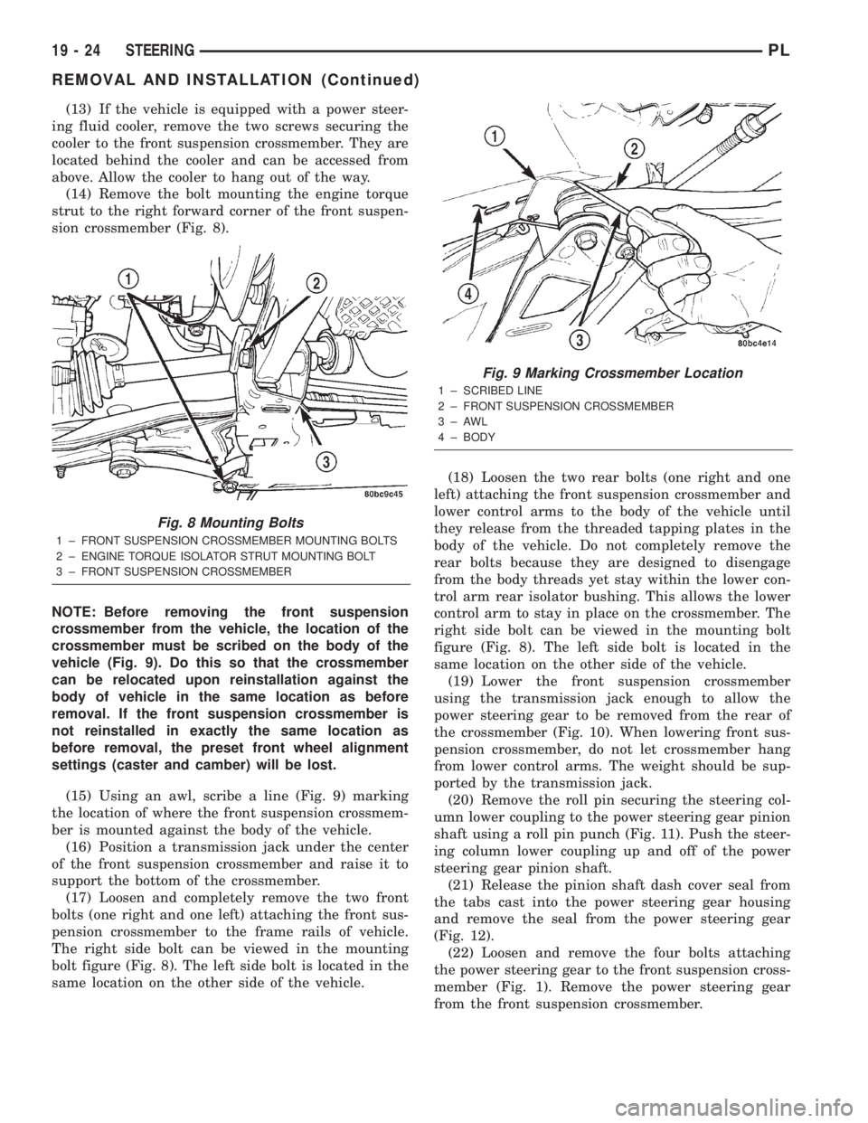
(14) Remove the bolt mounting the engine torque
strut to the right forward corner of the front suspen-
sion crossmember (Fig. 8).
NOTE: Before removing the front suspension
crossmember from the vehicle, the location of the
crossmember must be scribed on the body of the
vehicle (Fig. 9). Do this so that the crossmember
can be relocated upon reinstallation against the
body of vehicle in the same location as before
removal. If the front suspension crossmember is
not reinstalled in exactly the same location as
before removal, the preset front wheel alignment
settings (caster and camber) will be lost.
(15) Using an awl, scribe a line (Fig. 9) marking
the location of where the front suspension crossmem-
ber is mounted against the body of the vehicle.
(16) Position a transmission jack under the center
of the front suspension crossmember and raise it to
support the bottom of the crossmember.
(17) Loosen and completely remove the two front
bolts (one right and one left) attaching the front sus-
pension crossmember to the frame rails of vehicle.
The right side bolt can be viewed in the mounting
bolt figure (Fig. 8). The left side bolt is located in the
same location on the other side of the vehicle.(18) Loosen the two rear bolts (one right and one
left) attaching the front suspension crossmember and
lower control arms to the body of the vehicle until
they release from the threaded tapping plates in the
body of the vehicle. Do not completely remove the
rear bolts because they are designed to disengage
from the body threads yet stay within the lower con-
trol arm rear isolator bushing. This allows the lower
control arm to stay in place on the crossmember. The
right side bolt can be viewed in the mounting bolt
figure (Fig. 8). The left side bolt is located in the
same location on the other side of the vehicle.
(19) Lower the front suspension crossmember
using the transmission jack enough to allow the
power steering gear to be removed from the rear of
the crossmember (Fig. 10). When lowering front sus-
pension crossmember, do not let crossmember hang
from lower control arms. The weight should be sup-
ported by the transmission jack.
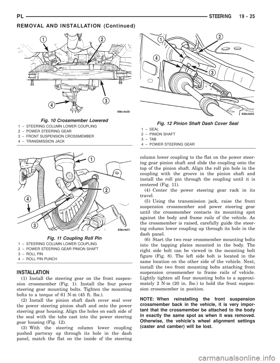
(20) Remove the roll pin securing the steering col-
umn lower coupling to the power steering gear pinion
shaft using a roll pin punch (Fig. 11). Push the steer-
ing column lower coupling up and off of the power
steering gear pinion shaft.
(21) Release the pinion shaft dash cover seal from
the tabs cast into the power steering gear housing
and remove the seal from the power steering gear
(Fig. 12).
(22) Loosen and remove the four bolts attaching
the power steering gear to the front suspension cross-
member (Fig. 1). Remove the power steering gear
from the front suspension crossmember.
Fig. 8 Mounting Bolts
1 ± FRONT SUSPENSION CROSSMEMBER MOUNTING BOLTS
2 ± ENGINE TORQUE ISOLATOR STRUT MOUNTING BOLT
3 ± FRONT SUSPENSION CROSSMEMBER
Fig. 9 Marking Crossmember Location
1 ± SCRIBED LINE
2 ± FRONT SUSPENSION CROSSMEMBER
3±AWL
4 ± BODY
19 - 24 STEERINGPL
REMOVAL AND INSTALLATION (Continued)
Page 896 of 1285
INSTALLATION
(1) Install the steering gear on the front suspen-
sion crossmember (Fig. 1). Install the four power
steering gear mounting bolts. Tighten the mounting
bolts to a torque of 61 N´m (45 ft. lbs.).
(2) Install the pinion shaft dash cover seal over
the power steering pinion shaft and onto the power
steering gear housing. Align the holes on each side of
the seal with the tabs cast into the power steering
gear housing (Fig. 12).
(3) With the steering column lower coupling
pushed partway up through its hole in the dash
panel, match the flat on the inside of the steeringcolumn lower coupling to the flat on the power steer-
ing gear pinion shaft and slide the coupling onto the
top of the pinion shaft. Align the roll pin hole in the
coupling with the groove in the pinion shaft and
install the roll pin through the coupling until it is
centered (Fig. 11).
(4) Center the power steering gear rack in its
travel.
(5) Using the transmission jack, raise the front
suspension crossmember and power steering gear
until the crossmember contacts its mounting spot
against the body and frame rails of the vehicle. As
the crossmember is raised, carefully guide the steer-
ing column lower coupling up through its hole in the
dash panel.
(6) Start the two rear crossmember mounting bolts
into the tapping plates mounted in the body. The
right side bolt can be viewed in the mounting bolt
figure (Fig. 8). The left side bolt is located in the
same location on the other side of the vehicle. Next,
install the two front mounting bolts attaching front
suspension crossmember to frame rails of vehicle.
Lightly tighten all four mounting bolts to a approxi-
mately 2 N´m (20 in. lbs.) to hold the front suspen-
sion crossmember in position.
NOTE: When reinstalling the front suspension
crossmember back in the vehicle, it is very impor-
tant that the crossmember be attached to the body
in exactly the same spot as when it was removed.
Otherwise, the vehicle's wheel alignment settings
(caster and camber) will be lost.
Fig. 10 Crossmember Lowered
1 ± STEERING COLUMN LOWER COUPLING
2 ± POWER STEERING GEAR
3 ± FRONT SUSPENSION CROSSMEMBER
4 ± TRANSMISSION JACK
Fig. 11 Coupling Roll Pin
1 ± STEERING COLUMN LOWER COUPLING
2 ± POWER STEERING GEAR PINION SHAFT
3 ± ROLL PIN
4 ± ROLL PIN PUNCH
Fig. 12 Pinion Shaft Dash Cover Seal
1 ± SEAL
2 ± PINION SHAFT
3±TAB
4 ± POWER STEERING GEAR
PLSTEERING 19 - 25
REMOVAL AND INSTALLATION (Continued)
Page 897 of 1285
(7) Using a soft face hammer, tap the front suspen-
sion crossmember back-and-forth or side-to-side until
it is aligned with the previously scribed positioning
marks on the body of the vehicle (Fig. 9). Once the
front suspension crossmember is correctly positioned,
tighten the rear two crossmember (and rear lower
control arm) mounting bolts to a torque of 203 N´m
(150 ft. lbs.), then tighten the front two crossmember
mounting bolts to a torque of 142 N´m (105 ft. lbs.).
(8) Fasten the engine torque strut to the right for-
ward corner of the front suspension crossmember
using its mounting bolt (Fig. 8). Follow the procedure
described in the ENGINE service manual group to
properly align and tighten the torque strut and it's
mounting bolts.
(9) Using a lint free towel, wipe clean the open
power steering hose ends and the power steering
gear ports. Replace the pressure hose used O-ring
with new. Lubricate the O-ring with power steering
fluid.
(10) Attach the power steering fluid pressure hose
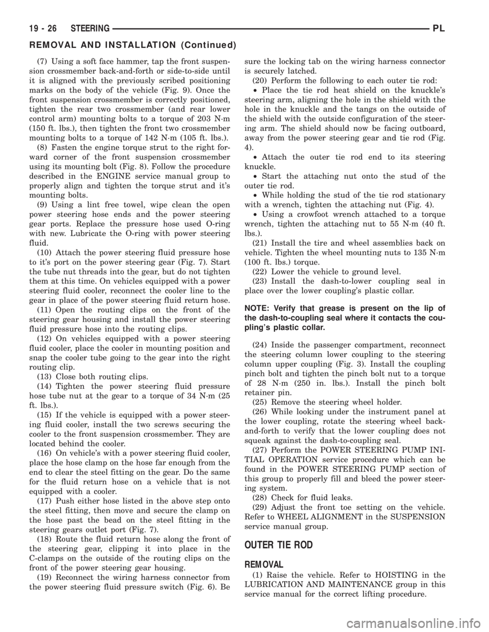
to it's port on the power steering gear (Fig. 7). Start
the tube nut threads into the gear, but do not tighten
them at this time. On vehicles equipped with a power
steering fluid cooler, reconnect the cooler line to the
gear in place of the power steering fluid return hose.
(11) Open the routing clips on the front of the
steering gear housing and install the power steering
fluid pressure hose into the routing clips.
(12) On vehicles equipped with a power steering
fluid cooler, place the cooler in mounting position and
snap the cooler tube going to the gear into the right
routing clip.
(13) Close both routing clips.
(14) Tighten the power steering fluid pressure
hose tube nut at the gear to a torque of 34 N´m (25
ft. lbs.).
(15) If the vehicle is equipped with a power steer-
ing fluid cooler, install the two screws securing the
cooler to the front suspension crossmember. They are
located behind the cooler.
(16) On vehicle's with a power steering fluid cooler,
place the hose clamp on the hose far enough from the
end to clear the steel fitting on the gear. Do the same
for the fluid return hose on a vehicle that is not
equipped with a cooler.
(17) Push either hose listed in the above step onto
the steel fitting, then move and secure the clamp on
the hose past the bead on the steel fitting in the
steering gears outlet port (Fig. 7).
(18) Route the fluid return hose along the front of
the steering gear, clipping it into place in the
C-clamps on the outside of the routing clips on the
front of the power steering gear housing.
(19) Reconnect the wiring harness connector from
the power steering fluid pressure switch (Fig. 6). Besure the locking tab on the wiring harness connector
is securely latched.
(20) Perform the following to each outer tie rod:
²Place the tie rod heat shield on the knuckle's
steering arm, aligning the hole in the shield with the
hole in the knuckle and the tangs on the outside of
the shield with the outside configuration of the steer-
ing arm. The shield should now be facing outboard,
away from the power steering gear and tie rod (Fig.
4).
²Attach the outer tie rod end to its steering
knuckle.
²Start the attaching nut onto the stud of the
outer tie rod.
²While holding the stud of the tie rod stationary
with a wrench, tighten the attaching nut (Fig. 4).
²Using a crowfoot wrench attached to a torque
wrench, tighten the attaching nut to 55 N´m (40 ft.
lbs.).
(21) Install the tire and wheel assemblies back on
vehicle. Tighten the wheel mounting nuts to 135 N´m
(100 ft. lbs.) torque.
(22) Lower the vehicle to ground level.
(23) Install the dash-to-lower coupling seal in
place over the lower coupling's plastic collar.
NOTE: Verify that grease is present on the lip of
the dash-to-coupling seal where it contacts the cou-
pling's plastic collar.
(24) Inside the passenger compartment, reconnect
the steering column lower coupling to the steering
column upper coupling (Fig. 3). Install the coupling
pinch bolt and tighten the pinch bolt nut to a torque
of 28 N´m (250 in. lbs.). Install the pinch bolt
retainer pin.
(25) Remove the steering wheel holder.
(26) While looking under the instrument panel at
the lower coupling, rotate the steering wheel back-
and-forth to verify that the lower coupling does not
squeak against the dash-to-coupling seal.
(27) Perform the POWER STEERING PUMP INI-
TIAL OPERATION service procedure which can be
found in the POWER STEERING PUMP section of
this group to properly fill and bleed the power steer-
ing system.
(28) Check for fluid leaks.
(29) Adjust the front toe setting on the vehicle.
Refer to WHEEL ALIGNMENT in the SUSPENSION
service manual group.
OUTER TIE ROD
REMOVAL
(1) Raise the vehicle. Refer to HOISTING in the
LUBRICATION AND MAINTENANCE group in this
service manual for the correct lifting procedure.
19 - 26 STEERINGPL
REMOVAL AND INSTALLATION (Continued)
Page 899 of 1285
(9) While holding the stud of the tie rod stationary
with a wrench, tighten the attaching nut (Fig. 14).
(10) Using a crowfoot wrench attached to a torque
wrench, tighten the attaching nut to 75 N´m (55 ft.
lbs.).
(11) Install the tire and wheel assembly.
(12) Lower the vehicle.
(13) Adjust the front toe setting on the vehicle.
Refer to WHEEL ALIGNMENT in the SUSPENSION
service manual group.
SPECIFICATIONS
POWER STEERING GEAR FASTENER TORQUE
SPECIFICATIONS
DESCRIPTION TORQUE
FRONT SUSPENSION CROSSMEMBER:
Front Mounting Bolts..... 142N´m(105 ft. lbs.)
Rear Mounting Bolts..... 203N´m(150 ft. lbs.)
STEERING GEAR:
Mounting Bolts........... 61N´m(45ft.lbs.)
OUTER TIE ROD:
Steering Knuckle Nut...... 55N´m(40ft.lbs.)
TieRodJamNut .......... 75N´m(55ft.lbs.)
POWER STEERING HOSE:
Tube Nuts............... 34N´m(25ft.lbs.)
SPECIAL TOOLS
POWER STEERING GEAR
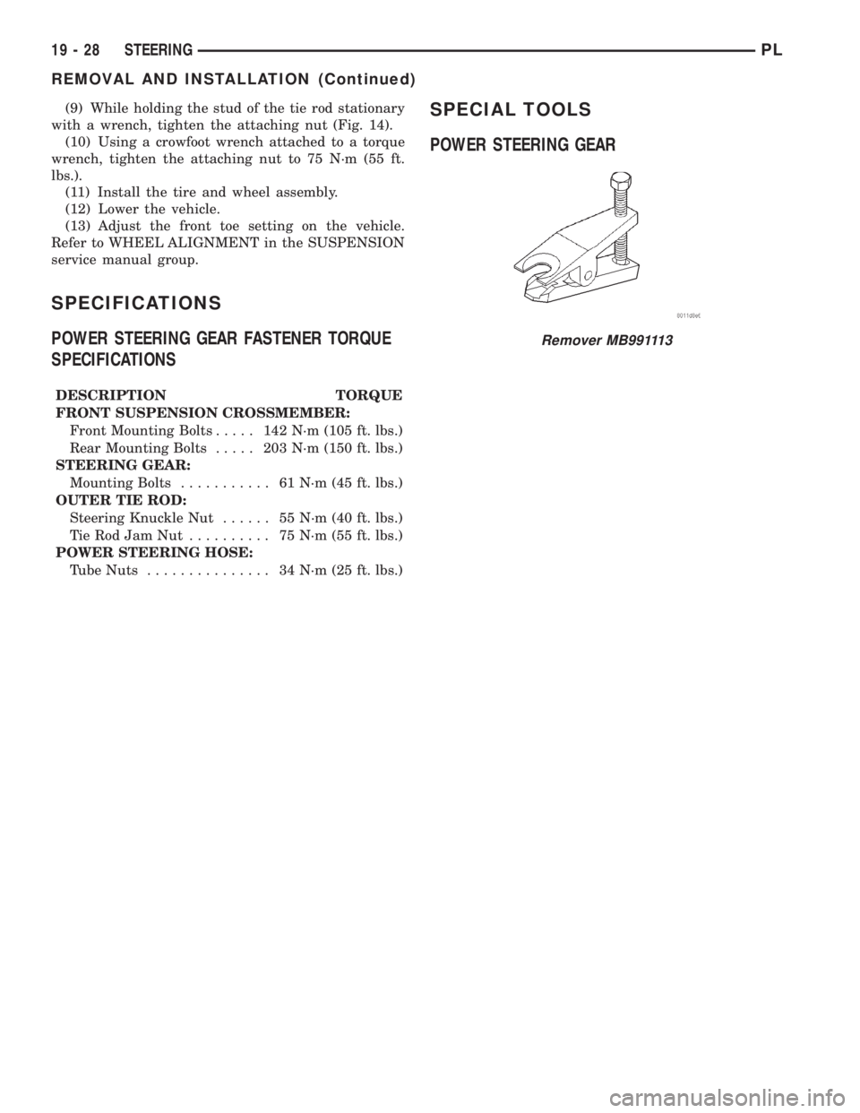
Remover MB991113
19 - 28 STEERINGPL
REMOVAL AND INSTALLATION (Continued)
Page 910 of 1285
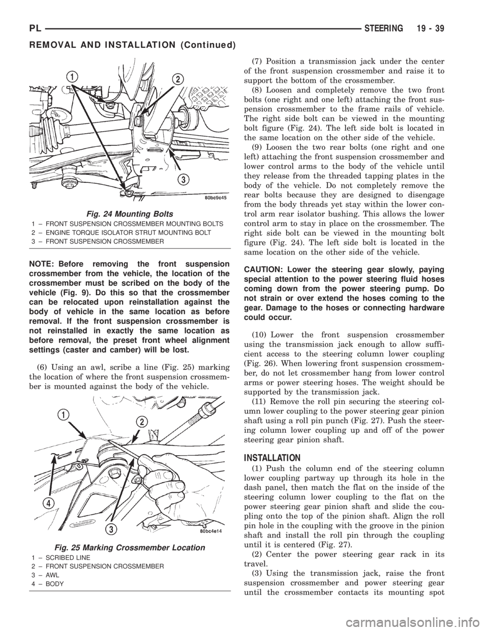
NOTE: Before removing the front suspension
crossmember from the vehicle, the location of the
crossmember must be scribed on the body of the
vehicle (Fig. 9). Do this so that the crossmember
can be relocated upon reinstallation against the
body of vehicle in the same location as before
removal. If the front suspension crossmember is
not reinstalled in exactly the same location as
before removal, the preset front wheel alignment
settings (caster and camber) will be lost.
(6) Using an awl, scribe a line (Fig. 25) marking
the location of where the front suspension crossmem-
ber is mounted against the body of the vehicle.(7) Position a transmission jack under the center
of the front suspension crossmember and raise it to
support the bottom of the crossmember.
(8) Loosen and completely remove the two front
bolts (one right and one left) attaching the front sus-
pension crossmember to the frame rails of vehicle.
The right side bolt can be viewed in the mounting
bolt figure (Fig. 24). The left side bolt is located in
the same location on the other side of the vehicle.
(9) Loosen the two rear bolts (one right and one
left) attaching the front suspension crossmember and
lower control arms to the body of the vehicle until
they release from the threaded tapping plates in the
body of the vehicle. Do not completely remove the
rear bolts because they are designed to disengage
from the body threads yet stay within the lower con-
trol arm rear isolator bushing. This allows the lower
control arm to stay in place on the crossmember. The
right side bolt can be viewed in the mounting bolt
figure (Fig. 24). The left side bolt is located in the
same location on the other side of the vehicle.
CAUTION: Lower the steering gear slowly, paying
special attention to the power steering fluid hoses
coming down from the power steering pump. Do
not strain or over extend the hoses coming to the
gear. Damage to the hoses or connecting hardware
could occur.
(10) Lower the front suspension crossmember
using the transmission jack enough to allow suffi-
cient access to the steering column lower coupling
(Fig. 26). When lowering front suspension crossmem-
ber, do not let crossmember hang from lower control
arms or power steering hoses. The weight should be
supported by the transmission jack.
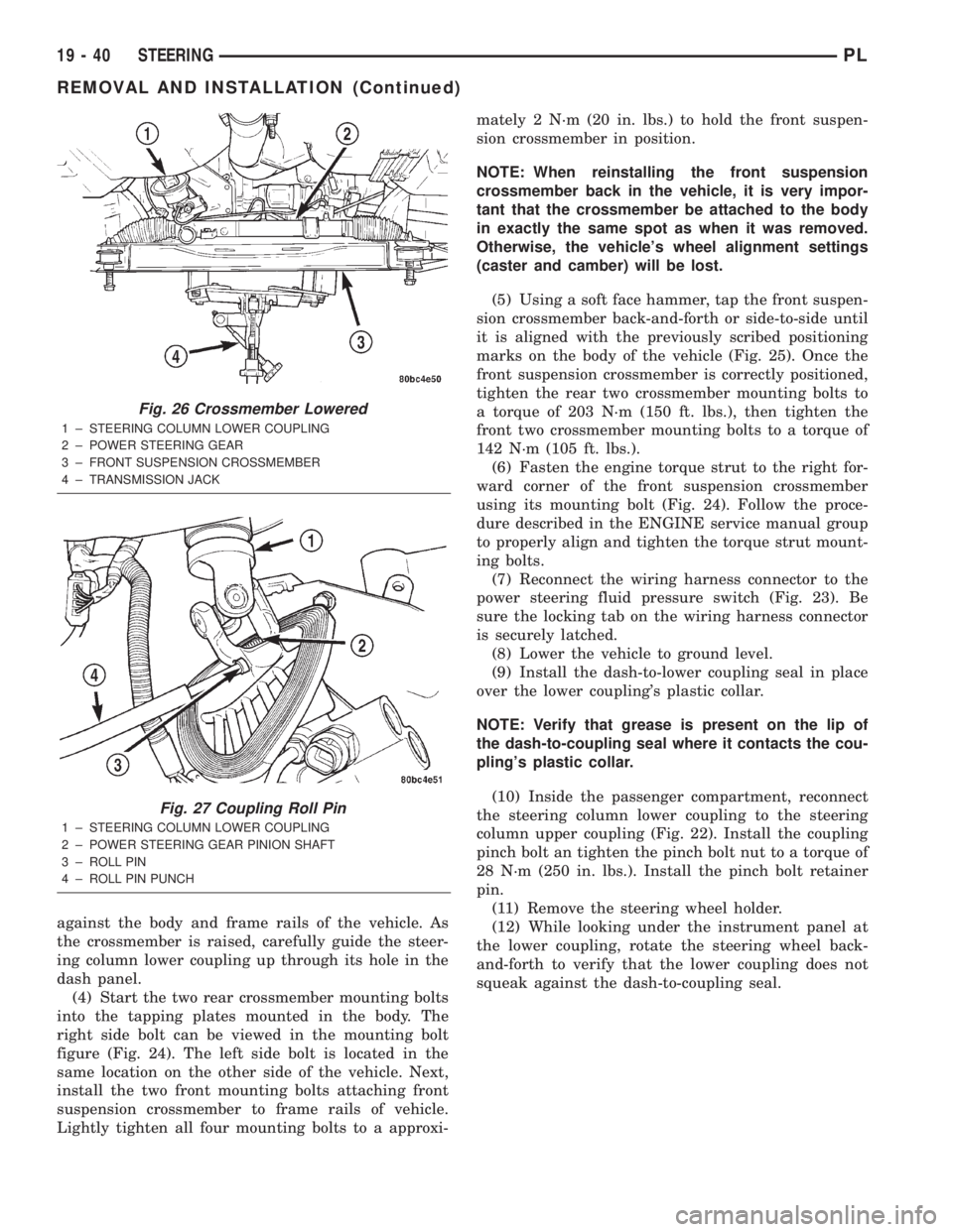
(11) Remove the roll pin securing the steering col-
umn lower coupling to the power steering gear pinion
shaft using a roll pin punch (Fig. 27). Push the steer-
ing column lower coupling up and off of the power
steering gear pinion shaft.
INSTALLATION
(1) Push the column end of the steering column
lower coupling partway up through its hole in the
dash panel, then match the flat on the inside of the
steering column lower coupling to the flat on the
power steering gear pinion shaft and slide the cou-
pling onto the top of the pinion shaft. Align the roll
pin hole in the coupling with the groove in the pinion
shaft and install the roll pin through the coupling
until it is centered (Fig. 27).
(2) Center the power steering gear rack in its
travel.
(3) Using the transmission jack, raise the front
suspension crossmember and power steering gear
until the crossmember contacts its mounting spot
Fig. 24 Mounting Bolts
1 ± FRONT SUSPENSION CROSSMEMBER MOUNTING BOLTS
2 ± ENGINE TORQUE ISOLATOR STRUT MOUNTING BOLT
3 ± FRONT SUSPENSION CROSSMEMBER
Fig. 25 Marking Crossmember Location
1 ± SCRIBED LINE
2 ± FRONT SUSPENSION CROSSMEMBER
3±AWL
4 ± BODY
PLSTEERING 19 - 39
REMOVAL AND INSTALLATION (Continued)
Page 911 of 1285
against the body and frame rails of the vehicle. As
the crossmember is raised, carefully guide the steer-
ing column lower coupling up through its hole in the
dash panel.
(4) Start the two rear crossmember mounting bolts
into the tapping plates mounted in the body. The
right side bolt can be viewed in the mounting bolt
figure (Fig. 24). The left side bolt is located in the
same location on the other side of the vehicle. Next,
install the two front mounting bolts attaching front
suspension crossmember to frame rails of vehicle.
Lightly tighten all four mounting bolts to a approxi-mately 2 N´m (20 in. lbs.) to hold the front suspen-
sion crossmember in position.
NOTE: When reinstalling the front suspension
crossmember back in the vehicle, it is very impor-
tant that the crossmember be attached to the body
in exactly the same spot as when it was removed.
Otherwise, the vehicle's wheel alignment settings
(caster and camber) will be lost.
(5) Using a soft face hammer, tap the front suspen-
sion crossmember back-and-forth or side-to-side until
it is aligned with the previously scribed positioning
marks on the body of the vehicle (Fig. 25). Once the
front suspension crossmember is correctly positioned,
tighten the rear two crossmember mounting bolts to
a torque of 203 N´m (150 ft. lbs.), then tighten the
front two crossmember mounting bolts to a torque of
142 N´m (105 ft. lbs.).
(6) Fasten the engine torque strut to the right for-
ward corner of the front suspension crossmember
using its mounting bolt (Fig. 24). Follow the proce-
dure described in the ENGINE service manual group
to properly align and tighten the torque strut mount-
ing bolts.
(7) Reconnect the wiring harness connector to the
power steering fluid pressure switch (Fig. 23). Be
sure the locking tab on the wiring harness connector
is securely latched.
(8) Lower the vehicle to ground level.
(9) Install the dash-to-lower coupling seal in place
over the lower coupling's plastic collar.
NOTE: Verify that grease is present on the lip of
the dash-to-coupling seal where it contacts the cou-
pling's plastic collar.
(10) Inside the passenger compartment, reconnect
the steering column lower coupling to the steering
column upper coupling (Fig. 22). Install the coupling
pinch bolt an tighten the pinch bolt nut to a torque of
28 N´m (250 in. lbs.). Install the pinch bolt retainer
pin.
(11) Remove the steering wheel holder.
(12) While looking under the instrument panel at
the lower coupling, rotate the steering wheel back-
and-forth to verify that the lower coupling does not
squeak against the dash-to-coupling seal.
Fig. 26 Crossmember Lowered
1 ± STEERING COLUMN LOWER COUPLING
2 ± POWER STEERING GEAR
3 ± FRONT SUSPENSION CROSSMEMBER
4 ± TRANSMISSION JACK
Fig. 27 Coupling Roll Pin
1 ± STEERING COLUMN LOWER COUPLING
2 ± POWER STEERING GEAR PINION SHAFT
3 ± ROLL PIN
4 ± ROLL PIN PUNCH
19 - 40 STEERINGPL
REMOVAL AND INSTALLATION (Continued)
Page 1073 of 1285
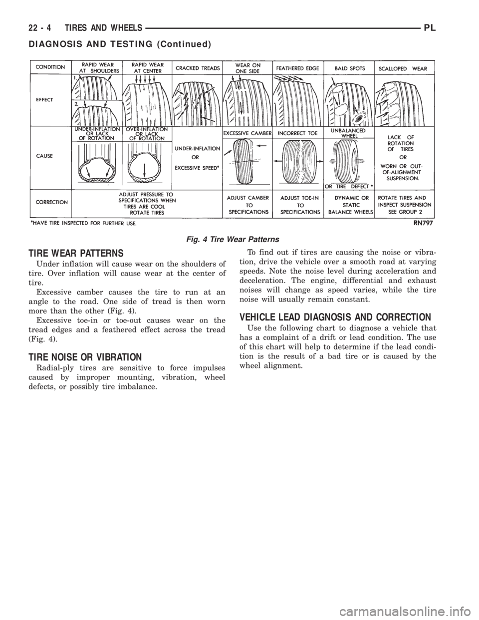
TIRE WEAR PATTERNS
Under inflation will cause wear on the shoulders of
tire. Over inflation will cause wear at the center of
tire.
Excessive camber causes the tire to run at an
angle to the road. One side of tread is then worn
more than the other (Fig. 4).
Excessive toe-in or toe-out causes wear on the
tread edges and a feathered effect across the tread
(Fig. 4).
TIRE NOISE OR VIBRATION
Radial-ply tires are sensitive to force impulses
caused by improper mounting, vibration, wheel
defects, or possibly tire imbalance.To find out if tires are causing the noise or vibra-
tion, drive the vehicle over a smooth road at varying
speeds. Note the noise level during acceleration and
deceleration. The engine, differential and exhaust
noises will change as speed varies, while the tire
noise will usually remain constant.
VEHICLE LEAD DIAGNOSIS AND CORRECTION
Use the following chart to diagnose a vehicle that
has a complaint of a drift or lead condition. The use
of this chart will help to determine if the lead condi-
tion is the result of a bad tire or is caused by the
wheel alignment.
Fig. 4 Tire Wear Patterns
22 - 4 TIRES AND WHEELSPL
DIAGNOSIS AND TESTING (Continued)