2000 DODGE NEON wheel alignment
[x] Cancel search: wheel alignmentPage 48 of 1285
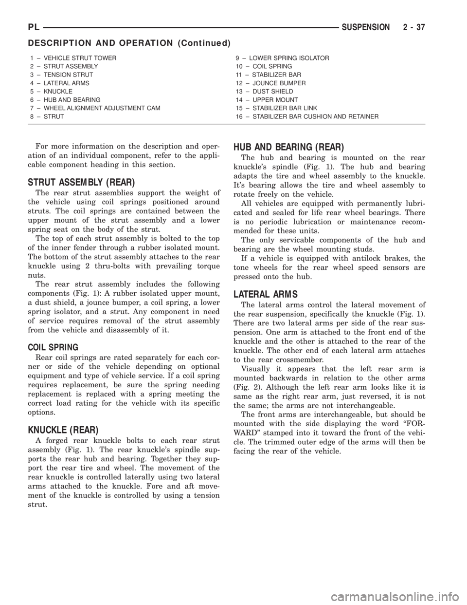
For more information on the description and oper-
ation of an individual component, refer to the appli-
cable component heading in this section.
STRUT ASSEMBLY (REAR)
The rear strut assemblies support the weight of
the vehicle using coil springs positioned around
struts. The coil springs are contained between the
upper mount of the strut assembly and a lower
spring seat on the body of the strut.
The top of each strut assembly is bolted to the top
of the inner fender through a rubber isolated mount.
The bottom of the strut assembly attaches to the rear
knuckle using 2 thru-bolts with prevailing torque
nuts.
The rear strut assembly includes the following
components (Fig. 1): A rubber isolated upper mount,
a dust shield, a jounce bumper, a coil spring, a lower
spring isolator, and a strut. Any component in need
of service requires removal of the strut assembly
from the vehicle and disassembly of it.
COIL SPRING
Rear coil springs are rated separately for each cor-
ner or side of the vehicle depending on optional
equipment and type of vehicle service. If a coil spring
requires replacement, be sure the spring needing
replacement is replaced with a spring meeting the
correct load rating for the vehicle with its specific
options.
KNUCKLE (REAR)
A forged rear knuckle bolts to each rear strut
assembly (Fig. 1). The rear knuckle's spindle sup-
ports the rear hub and bearing. Together they sup-
port the rear tire and wheel. The movement of the
rear knuckle is controlled laterally using two lateral
arms attached to the knuckle. Fore and aft move-
ment of the knuckle is controlled by using a tension
strut.
HUB AND BEARING (REAR)
The hub and bearing is mounted on the rear
knuckle's spindle (Fig. 1). The hub and bearing
adapts the tire and wheel assembly to the knuckle.
It's bearing allows the tire and wheel assembly to
rotate freely on the vehicle.
All vehicles are equipped with permanently lubri-
cated and sealed for life rear wheel bearings. There
is no periodic lubrication or maintenance recom-
mended for these units.
The only servicable components of the hub and
bearing are the wheel mounting studs.
If a vehicle is equipped with antilock brakes, the
tone wheels for the rear wheel speed sensors are
pressed onto the hub.
LATERAL ARMS
The lateral arms control the lateral movement of
the rear suspension, specifically the knuckle (Fig. 1).
There are two lateral arms per side of the rear sus-
pension. One arm is attached to the front end of the
knuckle and the other is attached to the rear of the
knuckle. The other end of each lateral arm attaches
to the rear crossmember.
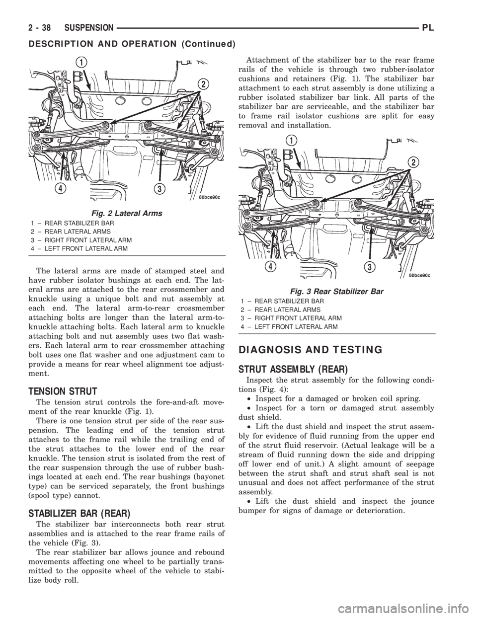
Visually it appears that the left rear arm is
mounted backwards in relation to the other arms
(Fig. 2). Although the left rear arm looks like it is
same as the right rear arm, just reversed, it is not
the same; the arms are not interchangeable.
The front arms are interchangeable, but should be
mounted with the side displaying the word ªFOR-
WARDº stamped into it toward the front of the vehi-
cle. The trimmed outer edge of the arms will then be
facing the rear of the vehicle.
1 ± VEHICLE STRUT TOWER
2 ± STRUT ASSEMBLY
3 ± TENSION STRUT
4 ± LATERAL ARMS
5 ± KNUCKLE
6 ± HUB AND BEARING
7 ± WHEEL ALIGNMENT ADJUSTMENT CAM
8 ± STRUT9 ± LOWER SPRING ISOLATOR
10 ± COIL SPRING
11 ± STABILIZER BAR
12 ± JOUNCE BUMPER
13 ± DUST SHIELD
14 ± UPPER MOUNT
15 ± STABILIZER BAR LINK
16 ± STABILIZER BAR CUSHION AND RETAINER
PLSUSPENSION 2 - 37
DESCRIPTION AND OPERATION (Continued)
Page 49 of 1285
The lateral arms are made of stamped steel and
have rubber isolator bushings at each end. The lat-
eral arms are attached to the rear crossmember and
knuckle using a unique bolt and nut assembly at
each end. The lateral arm-to-rear crossmember
attaching bolts are longer than the lateral arm-to-
knuckle attaching bolts. Each lateral arm to knuckle
attaching bolt and nut assembly uses two flat wash-
ers. Each lateral arm to rear crossmember attaching
bolt uses one flat washer and one adjustment cam to
provide a means for rear wheel alignment toe adjust-
ment.
TENSION STRUT
The tension strut controls the fore-and-aft move-
ment of the rear knuckle (Fig. 1).
There is one tension strut per side of the rear sus-
pension. The leading end of the tension strut
attaches to the frame rail while the trailing end of
the strut attaches to the lower end of the rear
knuckle. The tension strut is isolated from the rest of
the rear suspension through the use of rubber bush-
ings located at each end. The rear bushings (bayonet
type) can be serviced separately, the front bushings
(spool type) cannot.
STABILIZER BAR (REAR)
The stabilizer bar interconnects both rear strut
assemblies and is attached to the rear frame rails of
the vehicle (Fig. 3).
The rear stabilizer bar allows jounce and rebound
movements affecting one wheel to be partially trans-
mitted to the opposite wheel of the vehicle to stabi-
lize body roll.Attachment of the stabilizer bar to the rear frame
rails of the vehicle is through two rubber-isolator
cushions and retainers (Fig. 1). The stabilizer bar
attachment to each strut assembly is done utilizing a
rubber isolated stabilizer bar link. All parts of the
stabilizer bar are serviceable, and the stabilizer bar
to frame rail isolator cushions are split for easy
removal and installation.
DIAGNOSIS AND TESTING
STRUT ASSEMBLY (REAR)
Inspect the strut assembly for the following condi-
tions (Fig. 4):
²Inspect for a damaged or broken coil spring.
²Inspect for a torn or damaged strut assembly
dust shield.
²Lift the dust shield and inspect the strut assem-
bly for evidence of fluid running from the upper end
of the strut fluid reservoir. (Actual leakage will be a
stream of fluid running down the side and dripping
off lower end of unit.) A slight amount of seepage
between the strut shaft and strut shaft seal is not
unusual and does not affect performance of the strut
assembly.
²Lift the dust shield and inspect the jounce
bumper for signs of damage or deterioration.
Fig. 2 Lateral Arms
1 ± REAR STABILIZER BAR
2 ± REAR LATERAL ARMS
3 ± RIGHT FRONT LATERAL ARM
4 ± LEFT FRONT LATERAL ARM
Fig. 3 Rear Stabilizer Bar
1 ± REAR STABILIZER BAR
2 ± REAR LATERAL ARMS
3 ± RIGHT FRONT LATERAL ARM
4 ± LEFT FRONT LATERAL ARM
2 - 38 SUSPENSIONPL
DESCRIPTION AND OPERATION (Continued)
Page 56 of 1285
LATERAL ARMS
NOTE: Before proceeding with this procedure,
review SERVICE WARNINGS AND CAUTIONS at the
beginning of REMOVAL AND INSTALLATION in this
section.
Use the following procedure for removal and instal-
lation of one or both lateral arms on one side of the
vehicle's rear suspension.
REMOVAL
(1) Raise the vehicle. Refer to HOISTING in the
LUBRICATION AND MAINTENANCE group for the
proper lifting procedure.
(2) Remove the rear tire and wheel assembly.
(3) Remove the nut, bolt and washers attaching
both lateral arms to the knuckle (Fig. 1).
(4) Remove nut, washer, bolt and wheel alignment
cam attaching the lateral arms to the rear crossmem-
ber (Fig. 1).
(5) Remove the lateral arms from vehicle.
INSTALLATION
NOTE: Both lateral arms when being installed,
must be specifically positioned and orientated on
the vehicle. The lateral arm that has the same size
bushing sleeves on both ends must be mounted on
the forward side of the crossmember and knuckle
with the trimmed outer edge facing rearward. This
front arm is also marked with the word ªFOR-
WARDº. The side of the arm displaying this must
face forward.
The lateral arm with two different size bushing
sleeves must be mounted on the rearward side of
the crossmember and knuckle. Position the smaller
bushing sleeve end at the knuckle and the larger
bushing sleeve end at the rear crossmember (the
larger bushing sleeve is necessary to accommodate
the rear wheel alignment adjustment cam). If the
rear arm is to be mounted on the right side, the
trimmed outer edge must face rearward. If the rear
arm is to be mounted on the left side, the trimmed
outer edge must face forward.
(1) Following the note above, place the forward lat-
eral arm against the leading end of the knuckle, and
then install the short lateral arm mounting bolt with
a washer through the lateral arm and knuckle and
out the trailing end of the knuckle (Fig. 1).
(2) Following the note above, install the small
bushing sleeved end of the rear lateral arm onto the
end of the bolt just installed through the knuckle
(Fig. 1). Install a washer and nut onto the end of the
mounting bolt, but do not completely tighten the bolt
at this time.(3) Install a wheel alignment adjustment cam on
the long arm mounting bolt.
(4) Hold the rear lateral arm up against the cross-
member and install the long mounting bolt with the
adjustment cam through the lateral arm bushing and
rear crossmember (Fig. 1). The bolt must be installed
with the notch in the adjustment cam pointing
straight up.
(5) Position the forward lateral arm against the
rear crossmember hole. Pass the long mounting bolt
through the lateral arm bushing sleeve.
(6) Install a washer and nut onto the end of lateral
arm mounting bolt at the rear crossmember, but do
not completely tighten the bolt at this time.
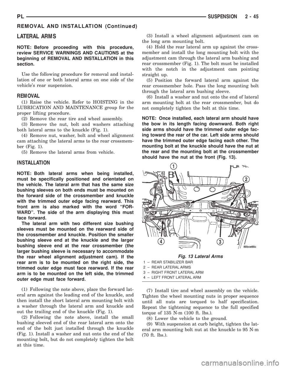
NOTE: Once installed, each lateral arm should have
the bow in its length facing downward. Both right
side arms should have the trimmed outer edge fac-
ing toward the rear of the car. Left side arms should
have the trimmed outer edge facing each other. The
mounting bolt at the knuckle should have the nut at
the rear and the mounting bolt at the crossmember
should have the nut at the front (Fig. 13).
(7) Install tire and wheel assembly on the vehicle.
Tighten the wheel mounting nuts in proper sequence
until all nuts are torqued to half specification.
Repeat the tightening sequence to the full specified
torque of 135 N´m (100 ft. lbs.).
(8) Lower the vehicle to the ground.
(9) With suspension at curb height, tighten the lat-
eral arm mounting bolt nut at the knuckle to 95 N´m
(70 ft. lbs.).
Fig. 13 Lateral Arms
1 ± REAR STABILIZER BAR
2 ± REAR LATERAL ARMS
3 ± RIGHT FRONT LATERAL ARM
4 ± LEFT FRONT LATERAL ARM
PLSUSPENSION 2 - 45
REMOVAL AND INSTALLATION (Continued)
Page 64 of 1285
SHUDDER OR VIBRATION DURING ACCELERATION
(1) A worn or damaged driveshaft inner tripod
joint.
(2) A sticking tripod joint spider assembly (inner
tripod joint only).
(3) Improper wheel alignment. See Wheel Align-
ment in this group for alignment checking and set-
ting procedures and specifications.
VIBRATION AT HIGHWAY SPEEDS
(1) Foreign material (mud, etc.) packed on the
backside of the wheel(s).
(2) Out of balance front tires or wheels. See Group
22, Wheels And Tires for the required balancing pro-
cedure.
(3) Improper tire and/or wheel runout. See Group
22, Wheels And Tires for the required runout check-
ing procedure.
REMOVAL AND INSTALLATION
DRIVESHAFTS
CAUTION: Boot sealing is vital to retain special
lubricants and to prevent foreign contaminants
from entering the C/V joint. Mishandling, such as
allowing the assemblies to dangle unsupported, or
pulling or pushing the ends can cut boots or dam-
age C/V joints. During removal and installation pro-
cedures, always support both ends of the driveshaft
to prevent damage.
REMOVAL
CAUTION: The driveshaft, when installed, acts as a
bolt and secures the front hub/bearing assembly. If
vehicle is to be supported or moved on its wheels
with a driveshaft removed, install a PROPER±SIZED
BOLT AND NUT through front hub. Tighten bolt and
nut to 203 N´m (150 ft. lbs.). This will ensure that
the hub bearing cannot loosen.
(1) Disconnect battery negative cable.
(2) Place transaxle in gated park.
(3) Raise vehicle on hoist.
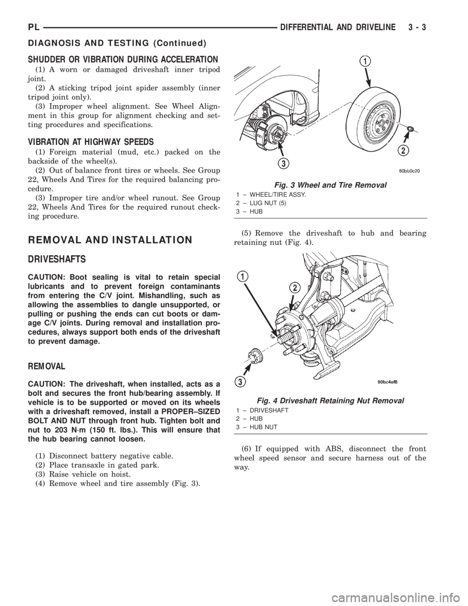
(4) Remove wheel and tire assembly (Fig. 3).(5) Remove the driveshaft to hub and bearing
retaining nut (Fig. 4).
(6) If equipped with ABS, disconnect the front
wheel speed sensor and secure harness out of the
way.
Fig. 3 Wheel and Tire Removal
1 ± WHEEL/TIRE ASSY.
2 ± LUG NUT (5)
3 ± HUB
Fig. 4 Driveshaft Retaining Nut Removal
1 ± DRIVESHAFT
2 ± HUB
3 ± HUB NUT
PLDIFFERENTIAL AND DRIVELINE 3 - 3
DIAGNOSIS AND TESTING (Continued)
Page 88 of 1285
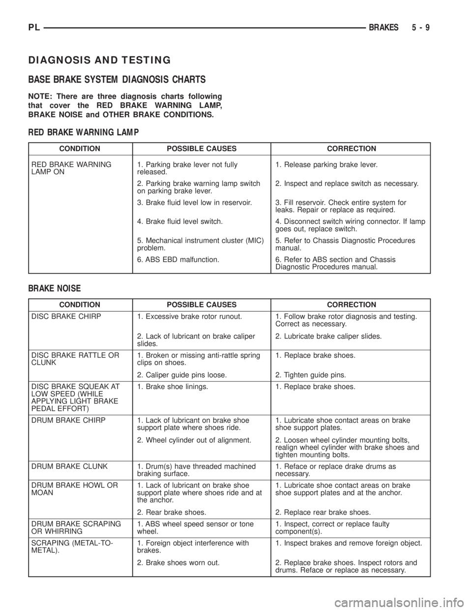
DIAGNOSIS AND TESTING
BASE BRAKE SYSTEM DIAGNOSIS CHARTS
NOTE: There are three diagnosis charts following
that cover the RED BRAKE WARNING LAMP,
BRAKE NOISE and OTHER BRAKE CONDITIONS.
RED BRAKE WARNING LAMP
CONDITION POSSIBLE CAUSES CORRECTION
RED BRAKE WARNING
LAMP ON1. Parking brake lever not fully
released.1. Release parking brake lever.
2. Parking brake warning lamp switch
on parking brake lever.2. Inspect and replace switch as necessary.
3. Brake fluid level low in reservoir. 3. Fill reservoir. Check entire system for
leaks. Repair or replace as required.
4. Brake fluid level switch. 4. Disconnect switch wiring connector. If lamp
goes out, replace switch.
5. Mechanical instrument cluster (MIC)
problem.5. Refer to Chassis Diagnostic Procedures
manual.
6. ABS EBD malfunction. 6. Refer to ABS section and Chassis
Diagnostic Procedures manual.
BRAKE NOISE
CONDITION POSSIBLE CAUSES CORRECTION
DISC BRAKE CHIRP 1. Excessive brake rotor runout. 1. Follow brake rotor diagnosis and testing.
Correct as necessary.
2. Lack of lubricant on brake caliper
slides.2. Lubricate brake caliper slides.
DISC BRAKE RATTLE OR
CLUNK1. Broken or missing anti-rattle spring
clips on shoes.1. Replace brake shoes.
2. Caliper guide pins loose. 2. Tighten guide pins.
DISC BRAKE SQUEAK AT
LOW SPEED (WHILE
APPLYING LIGHT BRAKE
PEDAL EFFORT)1. Brake shoe linings. 1. Replace brake shoes.
DRUM BRAKE CHIRP 1. Lack of lubricant on brake shoe
support plate where shoes ride.1. Lubricate shoe contact areas on brake
shoe support plates.
2. Wheel cylinder out of alignment. 2. Loosen wheel cylinder mounting bolts,
realign wheel cylinder with brake shoes and
tighten mounting bolts.
DRUM BRAKE CLUNK 1. Drum(s) have threaded machined
braking surface.1. Reface or replace drake drums as
necessary.
DRUM BRAKE HOWL OR
MOAN1. Lack of lubricant on brake shoe
support plate where shoes ride and at
the anchor.1. Lubricate shoe contact areas on brake
shoe support plates and at the anchor.
2. Rear brake shoes. 2. Replace rear brake shoes.
DRUM BRAKE SCRAPING
OR WHIRRING1. ABS wheel speed sensor or tone
wheel.1. Inspect, correct or replace faulty
component(s).
SCRAPING (METAL-TO-
METAL).1. Foreign object interference with
brakes.1. Inspect brakes and remove foreign object.
2. Brake shoes worn out. 2. Replace brake shoes. Inspect rotors and
drums. Reface or replace as necessary.
PLBRAKES 5 - 9
Page 111 of 1285
CAUTION: Use only a new brake booster input rod-
to-brake pedal retaining clip to ensure proper
retainment.
(4) Connect the power brake booster input rod-to-
brake pedal pin. Install a new retaining clip. Do not
use the old clip.
(5) Connect all previously removed vacuum hoses
to the vacuum check valve (Fig. 49).
(6) If the vehicle is equipped with ABS, install the
ICU mounting bracket on the frame rail using its
three bolts. Tighten the nuts to a torque of 23 N´m
(200 in. lbs.).
(7) If the vehicle is equipped with ABS, reinstall
the ICU. Refer to INTEGRATED CONTROL UNIT in
REMOVAL AND INSTALLATION within the
ANTILOCK BRAKE SYSTEM section of this service
manual group for the procedure.
(8) Install the master cylinder. For the master cyl-
inder without ABS removal and installation proce-
dure, refer to MASTER CYLINDER in this section of
this service manual group. For the master cylinder
with ABS removal and installation procedure, refer
to MASTER CYLINDER in the ANTILOCK BRAKE
SYSTEM section of this service manual group.
(9) Position the battery tray back in place. Install
the two bolts, then the two nuts mounting the bat-
tery tray to its bracket (Fig. 48). Tighten the two
bolts and nuts to a torque of 34 N´m (25 ft. lbs.).
(10) Reinstall the air cleaner box onto its grom-
meted alignment post (Fig. 48).
(11) Install the one nut and one bolt securing the
air cleaner box in place, then connect the wiring har-
ness connector at the air inlet sensor.
(12) Install the battery and clamp it in place.
(13) Connect the positive, then the negative
(ground) cable on the battery.
(14) Adjust the stop lamp switch as necessary.
Refer to STOP LAMP SWITCH in the ADJUST-
MENTS section of this group.
(15) Bleed the base brake system.
(16) Road test the vehicle to ensure proper opera-
tion of the brakes.
PROPORTIONING VALVE
NOTE: Before proceeding with this procedure,
review SERVICE WARNINGS AND CAUTIONS at the
beginning of REMOVAL AND INSTALLATION in this
section.
REMOVAL
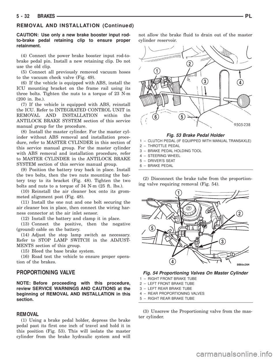
(1) Using a brake pedal holder, depress the brake
pedal past its first one inch of travel and hold it in
this position (Fig. 53). This will isolate the master
cylinder from the brake hydraulic system and willnot allow the brake fluid to drain out of the master
cylinder reservoir.
(2) Disconnect the brake tube from the proportion-
ing valve requiring removal (Fig. 54).
(3) Unscrew the Proportioning valve from the mas-
ter cylinder.
Fig. 53 Brake Pedal Holder
1 ± CLUTCH PEDAL (IF EQUIPPED WITH MANUAL TRANSAXLE)
2 ± THROTTLE PEDAL
3 ± BRAKE PEDAL HOLDING TOOL
4 ± STEERING WHEEL
5 ± DRIVER'S SEAT
6 ± BRAKE PEDAL
Fig. 54 Proportioning Valves On Master Cylinder
1 ± RIGHT FRONT BRAKE TUBE
2 ± LEFT FRONT BRAKE TUBE
3 ± LEFT REAR BRAKE TUBE
4 ± REAR PROPORTIONING VALVES
5 ± RIGHT REAR BRAKE TUBE
5 - 32 BRAKESPL
REMOVAL AND INSTALLATION (Continued)
Page 125 of 1285
(4) Remove the brake drum (Fig. 87).
NOTE: If the drum does not come off, further brake
clearance can be obtained by backing off the brake
automatic adjuster screw. Remove the rubber plug
from the top of brake support plate. Rotate the
automatic adjuster screw in an upward motion,
using a screwdriver.
INSTALLATION
NOTE: Before installing the drum, inspect the brake
shoe linings for wear, shoe alignment, and contam-
ination.
(1) Install the rear brake drum on rear hub and
bearing (Fig. 87).
(2) Install the tire and wheel assembly. Tighten
the wheel mounting nuts to a torque of 135 N´m (100
ft. lbs.).
(3) Adjust the rear brake shoes as necessary. Refer
to ADJUSTMENTS in this section of this service
manual group.
(4) Lower the vehicle.
DRUM BRAKE SHOE SUPPORT PLATE (REAR)
NOTE: Before proceeding with this procedure,
review SERVICE WARNINGS AND CAUTIONS at the
beginning of REMOVAL AND INSTALLATION in this
section.
REMOVAL
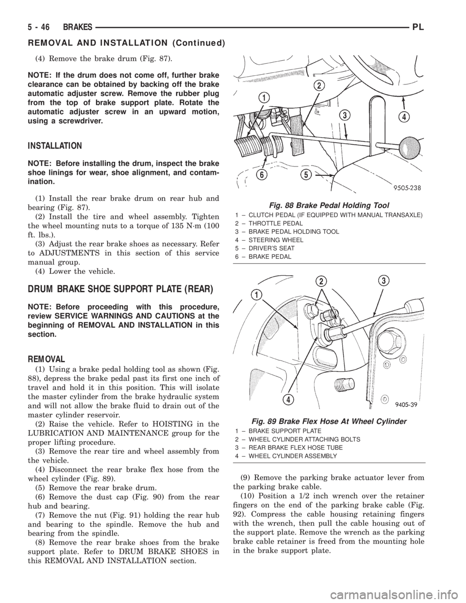
(1) Using a brake pedal holding tool as shown (Fig.
88), depress the brake pedal past its first one inch of
travel and hold it in this position. This will isolate
the master cylinder from the brake hydraulic system
and will not allow the brake fluid to drain out of the
master cylinder reservoir.
(2) Raise the vehicle. Refer to HOISTING in the
LUBRICATION AND MAINTENANCE group for the
proper lifting procedure.
(3) Remove the rear tire and wheel assembly from
the vehicle.
(4) Disconnect the rear brake flex hose from the
wheel cylinder (Fig. 89).
(5) Remove the rear brake drum.
(6) Remove the dust cap (Fig. 90) from the rear
hub and bearing.
(7) Remove the nut (Fig. 91) holding the rear hub
and bearing to the spindle. Remove the hub and
bearing from the spindle.
(8) Remove the rear brake shoes from the brake
support plate. Refer to DRUM BRAKE SHOES in
this REMOVAL AND INSTALLATION section.(9) Remove the parking brake actuator lever from
the parking brake cable.
(10) Position a 1/2 inch wrench over the retainer
fingers on the end of the parking brake cable (Fig.
92). Compress the cable housing retaining fingers
with the wrench, then pull the cable housing out of
the support plate. Remove the wrench as the parking
brake cable retainer is freed from the mounting hole
in the brake support plate.
Fig. 88 Brake Pedal Holding Tool
1 ± CLUTCH PEDAL (IF EQUIPPED WITH MANUAL TRANSAXLE)
2 ± THROTTLE PEDAL
3 ± BRAKE PEDAL HOLDING TOOL
4 ± STEERING WHEEL
5 ± DRIVER'S SEAT
6 ± BRAKE PEDAL
Fig. 89 Brake Flex Hose At Wheel Cylinder
1 ± BRAKE SUPPORT PLATE
2 ± WHEEL CYLINDER ATTACHING BOLTS
3 ± REAR BRAKE FLEX HOSE TUBE
4 ± WHEEL CYLINDER ASSEMBLY
5 - 46 BRAKESPL
REMOVAL AND INSTALLATION (Continued)
Page 155 of 1285
junction block. A label on the underside of the PDC
cover identifies the locations of the ABS fuses.
(2) Inspect the 25-way electrical connector at the
CAB for damaged, spread, or backed-out wiring ter-
minals. Verify that the 25-way connector is fully
inserted in the socket of the CAB. Be sure that wires
are not stretched tight or pulled out of the connector.
(3) Verify that all the wheel speed sensor connec-
tions are secure.
(4) Look for poor mating of connector halves or ter-
minals not fully seated in the connector body.
(5)
Check for improperly formed or damaged termi-
nals. All connector terminals in a suspect circuit should
be carefully reformed to increase contact tension.
(6) Look for poor terminal-to-wire connections.
This requires removing the terminal from the connec-
tor body to inspect it.
(7) Verify pin presence in the connector assembly
(8) Check for proper ground connections. Check all
ground connections for signs of corrosion, loose fas-
teners, or other potential defects. Refer to the wiring
diagrams for ground locations.
(9) Look for problems with the main power sources
of the vehicle. Inspect the battery, generator, ignition
circuits and other related relays and fuses.
If a visual check does not find the cause of the
problem, operate the car in an attempt to duplicate
the condition and record any trouble codes.
Most failures of the ABS disable the ABS function
for the entire ignition cycle even if the fault clears
before key-off. There are some failure conditions,
however, that allow ABS operation to resume during
the ignition cycle in which the trouble occurred even
if the trouble conditions are no longer present.
The following trouble conditions may result in
intermittent illumination of the amber ABS warning
lamp.
²Low system voltage. If Low System Voltage is
detected by the CAB, the CAB will turn on the ABS
Warning Lamp until normal system voltage is
achieved. Once normal voltage is seen at the CAB,
normal operation resumes.
²High system voltage. If high system voltage is
detected by the CAB, the CAB will turn on the
Amber ABS Warning Lamp until normal system volt-
age is achieved. Once normal voltage is again
detected by the CAB, normal ABS operation resumes.
Additional possible causes that may result in the
illumination of the amber ABS warning lamp are as
follows:
²Any condition that interrupts electrical current
to the CAB may cause the amber ABS warning lamp
to turn on intermittently.
²If PCI communication between the body control-
ler and the CAB is interrupted, the body controller
can turn on the amber ABS warning lamp.
TONE WHEEL
Tone wheels can cause erratic wheel speed sensor
signals. Inspect tone wheels for the following possible
causes:
²missing, chipped, or broken teeth
²contact with the wheel speed sensor
²wheel speed sensor to tone wheel alignment
²wheel speed sensor to tone wheel clearance
²excessive tone wheel runout
²tone wheel loose on its mounting surface
If a front tone wheel is found to need replacement,
the drive shaft must be replaced. No attempt should
be made to replace just the tone wheel. Refer to the
DIFFERENTIAL AND DRIVELINE group in this
service manual for removal and installation.
If a rear tone wheel is found to need replacement,
the rear hub and bearing must be replaced. No
attempt should be made to replace just the tone
wheel. Refer to the SUSPENSION group in this ser-
vice manual for removal and installation.
If wheel speed sensor to tone wheel contact is evi-
dent, determine the cause and correct it before
replacing the wheel speed sensor or tone wheel.
Check the gap between the speed sensor head and
the tone wheel to ensure it is within specifications.
Refer to SPECIFICATIONS in this section of the ser-
vice manual for the minimum and maximum wheel
speed sensor to tone wheel clearance.
Excessive wheel speed sensor runout can cause
erratic wheel speed sensor signals. Refer to SPECI-
FICATIONS in this section of the service manual for
the maximum allowed tone wheel runout. If tone
wheel runout is excessive, determine if it is caused
by a defect in the driveshaft assembly or hub and
bearing. Replace as necessary.
Tone wheels are pressed onto their mounting sur-
faces and should not rotate independently from the
mounting surface. Replacement of the front drive-
shaft or rear hub and bearing is necessary.
BRAKE FLUID CONTAMINATION
Indications of fluid contamination are swollen or
deteriorated rubber parts. Swelling indicates the
presence of petroleum in the brake fluid.
To test for contamination, put a small amount of
drained brake fluid in clear glass jar. If the fluid sep-
arates into layers, there is mineral oil or other fluid
contamination of the brake fluid.
If the brake fluid is contaminated, drain and thor-
oughly flush the brake system. Replace all the rubber
parts or components containing rubber coming into
contact with the brake fluid including: the master
cylinder; proportioning valves; caliper seals; wheel
cylinder seals; ABS hydraulic control unit; and all
hydraulic fluid hoses.
5 - 76 BRAKESPL
DIAGNOSIS AND TESTING (Continued)