2000 DODGE NEON roof
[x] Cancel search: roofPage 1123 of 1285
(10) Apply pinch weld primer 15 mm (.75 in.) wide
around the windshield fence. Allow at least three
minutes drying time.
(11) Apply a 10 mm (0.4 in.) bead of urethane on
center line of windshield fence.
(12) With the aid of a helper, position the wind-
shield over the windshield opening. Align the refer-
ence marks at the bottom of the windshield to the
support spacers.
(13) Slowly lower windshield glass to windshield
opening fence. Guide the molding into proper position
as necessary. Push windshield inward molding is
flush to roof line and A-pillars (Fig. 4).
(14) Clean access urethane from exterior with
Mopart, Super Clean or equivalent.
(15) Apply 150 mm (6 in.) lengths of 50 mm (2 in.)
masking tape spaced 250 mm (10 in.) apart to hold
molding in place until urethane cures.
(16) Install A-pillar moldings.
(17) Install cowl cover and wipers.
(18) Install inside rear view mirror.
(19) After urethane has cured, remove tape strips
and water test windshield to verify repair.
REAR WINDOW
WARNING: DO NOT OPERATE THE VEHICLE
WITHIN 24 HOURS OF WINDSHIELD INSTALLATION.IT TAKES AT LEAST 24 HOURS FOR URETHANE
ADHESIVE TO CURE. IF IT IS NOT CURED, THE
WINDSHIELD MAY NOT PERFORM PROPERLY IN
AN ACCIDENT. BE SURE TO REFER TO THE URE-
THANE MANUFACTURER'S DIRECTIONS FOR CUR-
ING TIME SPECIFICATIONS, AND DO NOT USE
ADHESIVE AFTER ITS EXPIRATION DATE.
CAUTION: Open the left front door glass before
installing the rear window to avoid pressurizing the
passenger compartment if a door is slammed
before the urethane bonding is fully cured. Water
leaks can result
Refer to the windshield paragraph of this section
for a description of tools and adhesive systems that
are recommended for use in this procedure.
REAR WINDOW REMOVAL
(1) Remove rear window moldings.
(2) Remove upper quarter trim panel.
(3) Disconnect wire connectors from rear window
defogger.
WARNING: WEAR EYE AND HAND PROTECTION
WHEN HANDLING SAFETY GLASS. PERSONAL
INJURY CAN RESULT.
CAUTION: Do not damage body or trim finish when
cutting out glass or applying fence primer.
(4) Cut the urethane around the perimeter of the
rear window glass. Refer to Windshield section of
this group for proper procedures.
(5) Remove the rear window from the vehicle.
REAR WINDOW INSTALLATION
(1) Prepare the work area, window fence, and
glass the same way as described in the Windshield
section of this group.
(2) Place fence spacers at the locations shown (Fig.
5).
(3) Install the rear window molding on glass.
(4) Apply a 10 mm (0.4 in.) bead of urethane
around the perimeter of the glass.
(5) Install the glass in the same manner described
in the Windshield section of this group (Fig. 5).
(6) Connect rear window defogger wiring and inte-
rior trim.
(7) After urethane has cured, water test rear win-
dow to verify repair. Verify rear window defogger
operation.
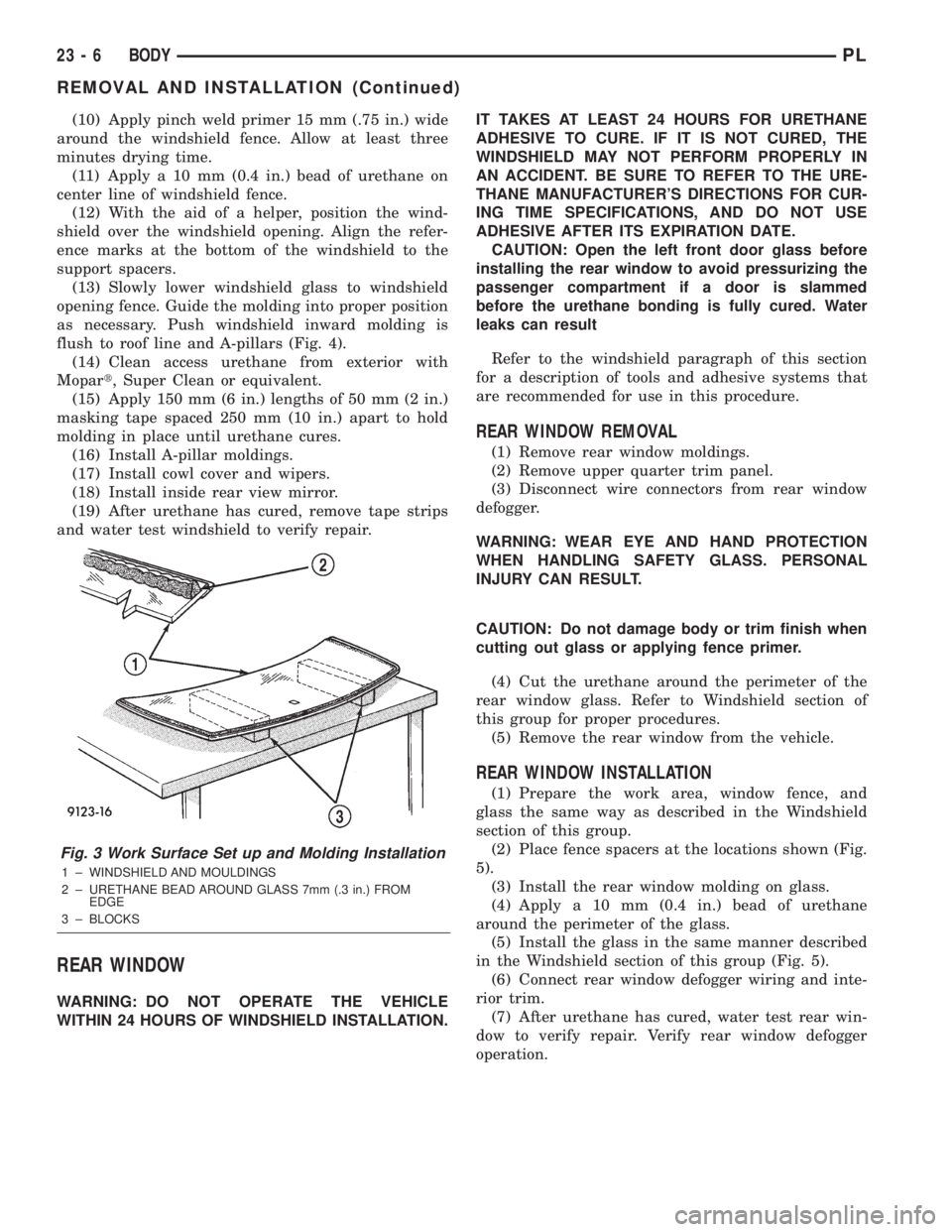
Fig. 3 Work Surface Set up and Molding Installation
1 ± WINDSHIELD AND MOULDINGS
2 ± URETHANE BEAD AROUND GLASS 7mm (.3 in.) FROM
EDGE
3 ± BLOCKS
23 - 6 BODYPL
REMOVAL AND INSTALLATION (Continued)
Page 1129 of 1285
BODY COMPONENTS
TABLE OF CONTENTS
page page
DESCRIPTION AND OPERATION
GRILLE................................13
HOOD.................................13
FRONT DOOR...........................14
SPLASH SHIELD.........................16
DIAGNOSIS AND TESTING
WATER LEAKS..........................18
WIND NOISE............................19
SERVICE PROCEDURES
HEAT STAKING..........................19
PLASTIC BODY PANEL REPAIR..............19
REMOVAL AND INSTALLATION
GRILLE................................23
HOOD LATCH...........................24
HOOD LATCH STRIKER....................24
HOOD RELEASE CABLE...................25
HOOD.................................26
HOOD SILENCER........................26
HOOD HINGE...........................26
COWL COVER...........................27
FRONT WHEELHOUSE SPLASH SHIELD......28
FENDER...............................28
EXTERIOR BADGEING ATTACHED WITH
DOUBLE SIDED FOAM TAPE..............28
EXTERIOR BADGEING/TAPE STRIPES
ATTACHED WITH ADHESIVES.............28
FRONT/REAR DOOR WINDOW CRANK........29
FRONT DOOR TRIM......................30
FRONT DOOR WATER DAM................30
DOOR OUTER BELT WEATHERSTRIP.........30
FRONT/REAR DOOR INNER BELT
WEATHERSTRIP........................32
FRONT DOOR GLASS RUN WEATHERSTRIP . . . 32
FRONT DOOR OUTSIDE HANDLE............33
DOOR LOCK CYLINDER...................33
FRONT DOOR LATCH.....................33
FRONT DOOR LATCH STRIKER.............34
FRONT VERTICAL GUIDE BAR..............34
FRONT DOOR GLASS.....................36
FRONT DOOR CHECK STRAP..............36
FRONT DOOR...........................36
FRONT DOOR HINGE.....................38
FRONT/REAR DOOR APPLIQUE.............38
SIDE VIEW MIRROR......................39
SIDE VIEW MIRROR TRIM BEZEL............39
DOOR UPPER SECONDARY WEATHERSTRIP . . 39
SILL SECONDARY WEATHERSTRIP..........40
REAR DOOR TRIM.......................40REAR DOOR WATER DAM.................40
REAR DOOR OUTSIDE HANDLE.............40
REAR DOOR LATCH......................41
REAR DOOR LATCH STRIKER..............43
REAR DOOR GLASS......................43
REAR DOOR WINDOW REGULATOR.........43
REAR DOOR GLASS RUN WEATHERSTRIP....43
REAR DOOR CHECK STRAP................45
REAR DOOR............................45
REAR DOOR HINGE......................45
FUEL FILL DOOR.........................46
DECKLID LATCH.........................47
DECKLID...............................47
DECKLID LIFT SPRINGS...................47
DECKLID LOCK CYLINDER.................48
DECKLID LATCH STRIKER.................48
DECKLID OPENING WEATHERSTRIP.........49
TRUNK CARPET.........................49
DECKLID COVER.........................50
ROOF RAIL WEATHERSTRIP................50
ROOF RAIL WEATHERSTRIP RETAINER
CHANNEL.............................50
B-PILLAR WEATHERSTRIP CHANNEL.........51
A-PILLAR TRIM..........................51
DOOR SILL TRIM.........................51
SIDE COWL TRIM........................52
B-PILLAR TRIM..........................52
UPPER QUARTER TRIM...................53
LOWER QUARTER TRIM...................53
FLOOR CONSOLE........................54
FRONT SEAT BELT BUCKLE................54
FRONT SEAT BELT RETRACTOR............54
FRONT SHOULDER BELT ADJUSTER.........54
REAR SEAT BELT BUCKLE.................55
REAR SEAT BELT RETRACTOR.............55
CARPET...............................56
SUN VISOR.............................56
HEADLINER.............................57
INSIDE REAR VIEW MIRROR...............57
REAR SHELF TRIM PANEL.................57
BODY VENT.............................58
ADJUSTMENTS
FRONT DOOR LATCH ADJUSTMENT.........58
REAR DOOR LATCH ADJUSTMENT..........58
SPECIFICATIONS
BODY LUBRICATION......................59
SPECIAL TOOLS
BODY.................................59
23 - 12 BODYPL
Page 1167 of 1285
DECKLID COVER
REMOVAL
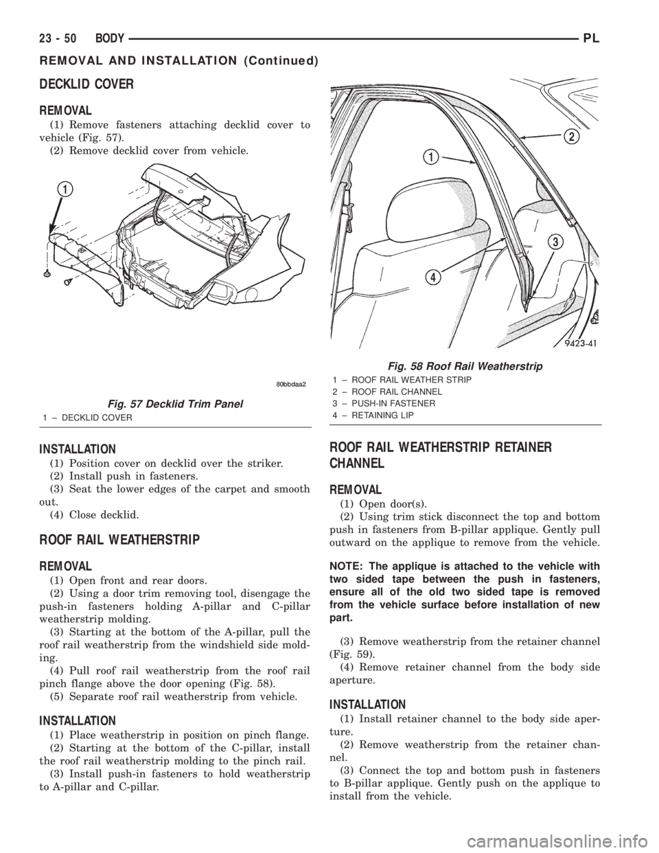
(1) Remove fasteners attaching decklid cover to
vehicle (Fig. 57).
(2) Remove decklid cover from vehicle.
INSTALLATION
(1) Position cover on decklid over the striker.
(2) Install push in fasteners.
(3) Seat the lower edges of the carpet and smooth
out.
(4) Close decklid.
ROOF RAIL WEATHERSTRIP
REMOVAL
(1) Open front and rear doors.
(2) Using a door trim removing tool, disengage the
push-in fasteners holding A-pillar and C-pillar
weatherstrip molding.
(3) Starting at the bottom of the A-pillar, pull the
roof rail weatherstrip from the windshield side mold-
ing.
(4) Pull roof rail weatherstrip from the roof rail
pinch flange above the door opening (Fig. 58).
(5) Separate roof rail weatherstrip from vehicle.
INSTALLATION
(1) Place weatherstrip in position on pinch flange.
(2) Starting at the bottom of the C-pillar, install
the roof rail weatherstrip molding to the pinch rail.
(3) Install push-in fasteners to hold weatherstrip
to A-pillar and C-pillar.
ROOF RAIL WEATHERSTRIP RETAINER
CHANNEL
REMOVAL
(1) Open door(s).
(2) Using trim stick disconnect the top and bottom
push in fasteners from B-pillar applique. Gently pull
outward on the applique to remove from the vehicle.
NOTE: The applique is attached to the vehicle with
two sided tape between the push in fasteners,
ensure all of the old two sided tape is removed
from the vehicle surface before installation of new
part.
(3) Remove weatherstrip from the retainer channel
(Fig. 59).
(4) Remove retainer channel from the body side
aperture.
INSTALLATION
(1) Install retainer channel to the body side aper-
ture.
(2) Remove weatherstrip from the retainer chan-
nel.
(3) Connect the top and bottom push in fasteners
to B-pillar applique. Gently push on the applique to
install from the vehicle.
Fig. 57 Decklid Trim Panel
1 ± DECKLID COVER
Fig. 58 Roof Rail Weatherstrip
1 ± ROOF RAIL WEATHER STRIP
2 ± ROOF RAIL CHANNEL
3 ± PUSH-IN FASTENER
4 ± RETAINING LIP
23 - 50 BODYPL
REMOVAL AND INSTALLATION (Continued)
Page 1168 of 1285
B-PILLAR WEATHERSTRIP CHANNEL
REMOVAL
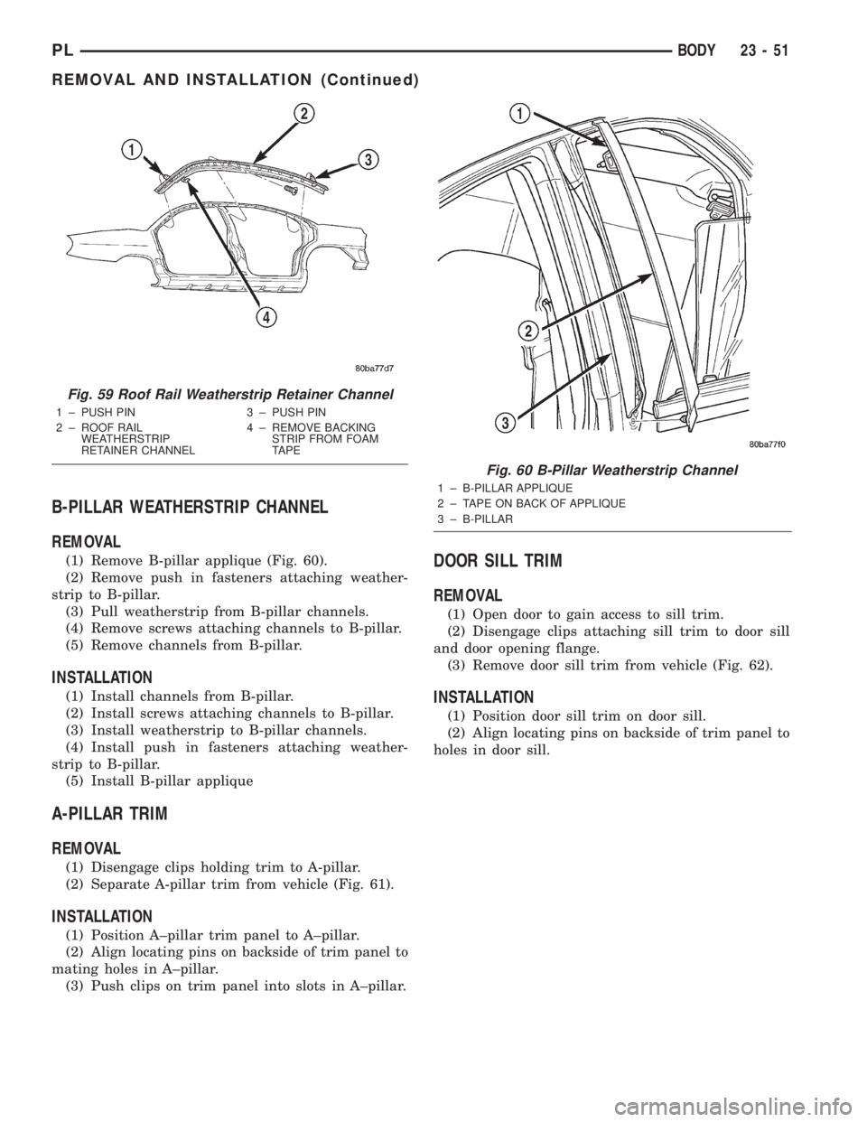
(1) Remove B-pillar applique (Fig. 60).
(2) Remove push in fasteners attaching weather-
strip to B-pillar.
(3) Pull weatherstrip from B-pillar channels.
(4) Remove screws attaching channels to B-pillar.
(5) Remove channels from B-pillar.
INSTALLATION
(1) Install channels from B-pillar.
(2) Install screws attaching channels to B-pillar.
(3) Install weatherstrip to B-pillar channels.
(4) Install push in fasteners attaching weather-
strip to B-pillar.
(5) Install B-pillar applique
A-PILLAR TRIM
REMOVAL
(1) Disengage clips holding trim to A-pillar.
(2) Separate A-pillar trim from vehicle (Fig. 61).
INSTALLATION
(1) Position A±pillar trim panel to A±pillar.
(2) Align locating pins on backside of trim panel to
mating holes in A±pillar.
(3) Push clips on trim panel into slots in A±pillar.
DOOR SILL TRIM
REMOVAL
(1) Open door to gain access to sill trim.
(2) Disengage clips attaching sill trim to door sill
and door opening flange.
(3) Remove door sill trim from vehicle (Fig. 62).
INSTALLATION
(1) Position door sill trim on door sill.
(2) Align locating pins on backside of trim panel to
holes in door sill.
Fig. 59 Roof Rail Weatherstrip Retainer Channel
1 ± PUSH PIN
2 ± ROOF RAIL
WEATHERSTRIP
RETAINER CHANNEL3 ± PUSH PIN
4 ± REMOVE BACKING
STRIP FROM FOAM
TAPE
Fig. 60 B-Pillar Weatherstrip Channel
1 ± B-PILLAR APPLIQUE
2 ± TAPE ON BACK OF APPLIQUE
3 ± B-PILLAR
PLBODY 23 - 51
REMOVAL AND INSTALLATION (Continued)
Page 1170 of 1285
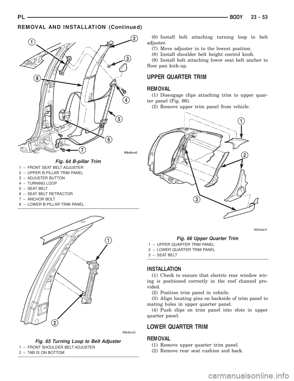
(6) Install bolt attaching turning loop to belt
adjuster.
(7) Move adjuster in to the lowest position.
(8) Install shoulder belt height control knob.
(9) Install bolt attaching lower seat belt anchor to
floor pan kick-up.
UPPER QUARTER TRIM
REMOVAL
(1) Disengage clips attaching trim to upper quar-
ter panel (Fig. 66).
(2) Remove upper trim panel from vehicle.
INSTALLATION
(1) Check to ensure that electric rear window wir-
ing is positioned correctly in the roof channel pro-
vided.
(2) Position trim panel in vehicle.
(3) Align locating pins on backside of trim panel to
mating holes in upper quarter panel.
(4) Push clips on trim panel into slots in upper
quarter panel.
LOWER QUARTER TRIM
REMOVAL
(1) Remove upper quarter trim panel.
(2) Remove rear seat cushion and back.
Fig. 64 B-pillar Trim
1 ± FRONT SEAT BELT ADJUSTER
2 ± UPPER B-PILLAR TRIM PANEL
3 ± ADJUSTER BUTTON
4 ± TURNING LOOP
5 ± SEAT BELT
6 ± SEAT BELT RETRACTOR
7 ± ANCHOR BOLT
8 ± LOWER B-PILLAR TRIM PANEL
Fig. 65 Turning Loop to Belt Adjuster
1 ± FRONT SHOULDER BELT ADJUSTER
2 ± TAB IS ON BOTTOM
Fig. 66 Upper Quarter Trim
1 ± UPPER QUARTER TRIM PANEL
2 ± LOWER QUARTER TRIM PANEL
3 ± SEAT BELT
PLBODY 23 - 53
REMOVAL AND INSTALLATION (Continued)
Page 1174 of 1285
warning label applied to the sun visor, verify label
availability and ensure the label is installed.
REMOVAL
(1) Remove sun visor from center support.
(2) Remove screws attaching sun visor to roof
header.
(3) Remove sun visor from header.
(4) If equipped, disconnect wire connector from
body harness.
(5) Remove sun visor from vehicle.
INSTALLATION
(1) Place sun visor in position.
(2) If equipped, connect wire connector from body
harness.
(3) Install screws attaching sun visor to header.
(4) Install sun visor into center support.
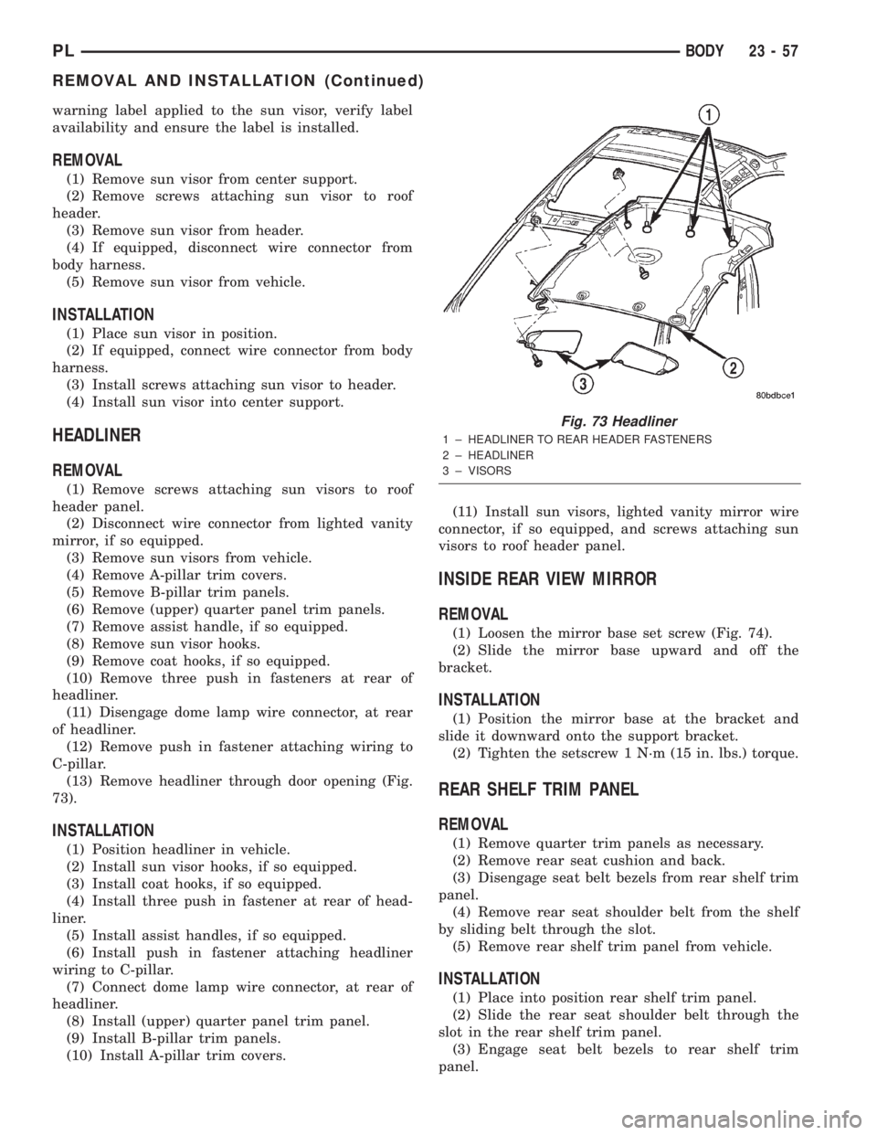
HEADLINER
REMOVAL
(1) Remove screws attaching sun visors to roof
header panel.
(2) Disconnect wire connector from lighted vanity
mirror, if so equipped.
(3) Remove sun visors from vehicle.
(4) Remove A-pillar trim covers.
(5) Remove B-pillar trim panels.
(6) Remove (upper) quarter panel trim panels.
(7) Remove assist handle, if so equipped.
(8) Remove sun visor hooks.
(9) Remove coat hooks, if so equipped.
(10) Remove three push in fasteners at rear of
headliner.
(11) Disengage dome lamp wire connector, at rear
of headliner.
(12) Remove push in fastener attaching wiring to
C-pillar.
(13) Remove headliner through door opening (Fig.
73).
INSTALLATION
(1) Position headliner in vehicle.
(2) Install sun visor hooks, if so equipped.
(3) Install coat hooks, if so equipped.
(4) Install three push in fastener at rear of head-
liner.
(5) Install assist handles, if so equipped.
(6) Install push in fastener attaching headliner
wiring to C-pillar.
(7) Connect dome lamp wire connector, at rear of
headliner.
(8) Install (upper) quarter panel trim panel.
(9) Install B-pillar trim panels.
(10) Install A-pillar trim covers.(11) Install sun visors, lighted vanity mirror wire
connector, if so equipped, and screws attaching sun
visors to roof header panel.
INSIDE REAR VIEW MIRROR
REMOVAL
(1) Loosen the mirror base set screw (Fig. 74).
(2) Slide the mirror base upward and off the
bracket.
INSTALLATION
(1) Position the mirror base at the bracket and
slide it downward onto the support bracket.
(2) Tighten the setscrew 1 N´m (15 in. lbs.) torque.
REAR SHELF TRIM PANEL
REMOVAL
(1) Remove quarter trim panels as necessary.
(2) Remove rear seat cushion and back.
(3) Disengage seat belt bezels from rear shelf trim
panel.
(4) Remove rear seat shoulder belt from the shelf
by sliding belt through the slot.
(5) Remove rear shelf trim panel from vehicle.
INSTALLATION
(1) Place into position rear shelf trim panel.
(2) Slide the rear seat shoulder belt through the
slot in the rear shelf trim panel.
(3) Engage seat belt bezels to rear shelf trim
panel.
Fig. 73 Headliner
1 ± HEADLINER TO REAR HEADER FASTENERS
2 ± HEADLINER
3 ± VISORS
PLBODY 23 - 57
REMOVAL AND INSTALLATION (Continued)
Page 1178 of 1285
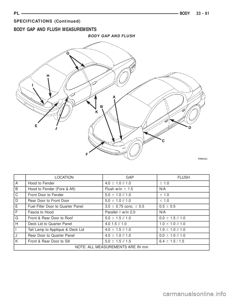
BODY GAP AND FLUSH MEASUREMENTS
BODY GAP AND FLUSH
LOCATION GAP FLUSH
A Hood to Fender 4.061.0 // 1.061.0
B Hood to Fender (Fore & Aft) Flush w/in61.5 N/A
C Front Door to Fender 5.061.0 // 1.061.0
D Rear Door to Front Door 5.061.0 // 1.061.0
E Fuel Filler Door to Quarter Panel 3.060.75 conc.60.5 0.560.5
F Fascia to Hood Parallel // w/in 2.0 N/A
G Front & Rear Door to Roof 5.061.5 // 1.0 0.061.5 // 1.0
H Deck Lid to Quarter Panel 4.0 1.5 // 1.0 1.061.0 // 1.0
I Tail Lamp to Applique & Deck Lid 4.061.5 // 1.0 1.061.0 // 1.0
J Rear Door to Quarter Panel 4.061.0 // 1.0 0.061.0 // 1.0
K Front & Rear Door to Sill 5.061.5 // 1.5 6.461.5 / 1.5
NOTE: ALL MEASUREMENTS ARE IN mm
PLBODY 23 - 61
SPECIFICATIONS (Continued)
Page 1185 of 1285
ROOF PANEL
23 - 68 BODYPL
SPECIFICATIONS (Continued)