2000 DODGE NEON relay
[x] Cancel search: relayPage 360 of 1285
POWER DISTRIBUTION SYSTEMS
TABLE OF CONTENTS
page page
DESCRIPTION AND OPERATION
POWER DISTRIBUTION SYSTEM.............1
POWER DISTRIBUTION CENTER (PDC).......1
FUSE BLOCK.............................2REMOVAL AND INSTALLATION
FUSE BLOCK.............................2
POWER DISTRIBUTION CENTER (PDC).......2
DESCRIPTION AND OPERATION
POWER DISTRIBUTION SYSTEM
This group covers the various standard and
optional power distribution components used on this
model. Refer to the Component Index of Group 8W -
Wiring Diagrams for complete circuit diagrams of the
various power distribution components.
The power distribution system for this vehicle is
designed to provide safe, reliable, centralized and
convenient to access distribution of the electrical cur-
rent required to operate all of the many standard
and optional factory-installed electrical and electronic
powertrain, chassis, safety, comfort and convenience
systems. At the same time, these systems were
designed to provide centralized locations for conduct-
ing diagnosis of faulty circuits, and for sourcing the
additional current requirements of many aftermarket
vehicle accessory and convenience items.
These power distribution systems also incorporate
various types of circuit control and protection fea-
tures, including:
²Fuses
²Fuse cartridges
²Fusible links
²Automatic resetting circuit breakers
²Relays
²Flashers
²Timers
²Circuit splice blocks.
The power distribution system for this vehicle con-
sists of the following components:
²Power Distribution Center (PDC)
²Fuse Block
Following are general descriptions of the major
components in the power distribution system. Refer
to the owner's manual in the vehicle glove box for
more information on the features, use and operation
of all of the power distribution system components.
POWER DISTRIBUTION CENTER (PDC)
All of the electrical current distributed throughout
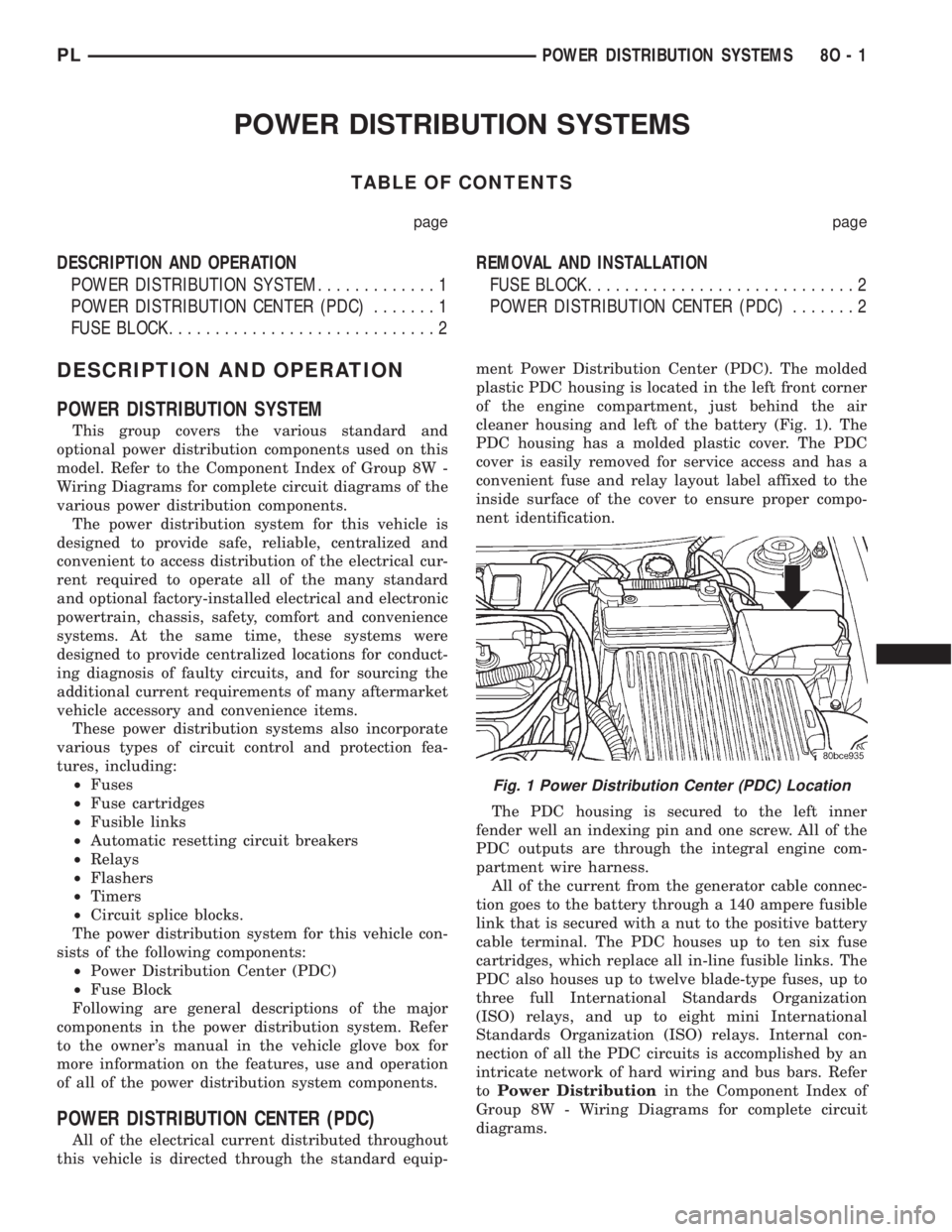
this vehicle is directed through the standard equip-ment Power Distribution Center (PDC). The molded
plastic PDC housing is located in the left front corner
of the engine compartment, just behind the air
cleaner housing and left of the battery (Fig. 1). The
PDC housing has a molded plastic cover. The PDC
cover is easily removed for service access and has a
convenient fuse and relay layout label affixed to the
inside surface of the cover to ensure proper compo-
nent identification.
The PDC housing is secured to the left inner
fender well an indexing pin and one screw. All of the
PDC outputs are through the integral engine com-
partment wire harness.
All of the current from the generator cable connec-
tion goes to the battery through a 140 ampere fusible
link that is secured with a nut to the positive battery
cable terminal. The PDC houses up to ten six fuse
cartridges, which replace all in-line fusible links. The
PDC also houses up to twelve blade-type fuses, up to
three full International Standards Organization
(ISO) relays, and up to eight mini International
Standards Organization (ISO) relays. Internal con-
nection of all the PDC circuits is accomplished by an
intricate network of hard wiring and bus bars. Refer
toPower Distributionin the Component Index of
Group 8W - Wiring Diagrams for complete circuit
diagrams.
Fig. 1 Power Distribution Center (PDC) Location
PLPOWER DISTRIBUTION SYSTEMS 8O - 1
Page 361 of 1285
The fusible link, fuses and relays are available for
service replacement. The PDC unit cannot be
repaired and is only serviced as a unit with the
engine compartment wire harness. If the PDC is
faulty or damaged, the engine compartment wire har-
ness assembly must be replaced.
FUSE BLOCK
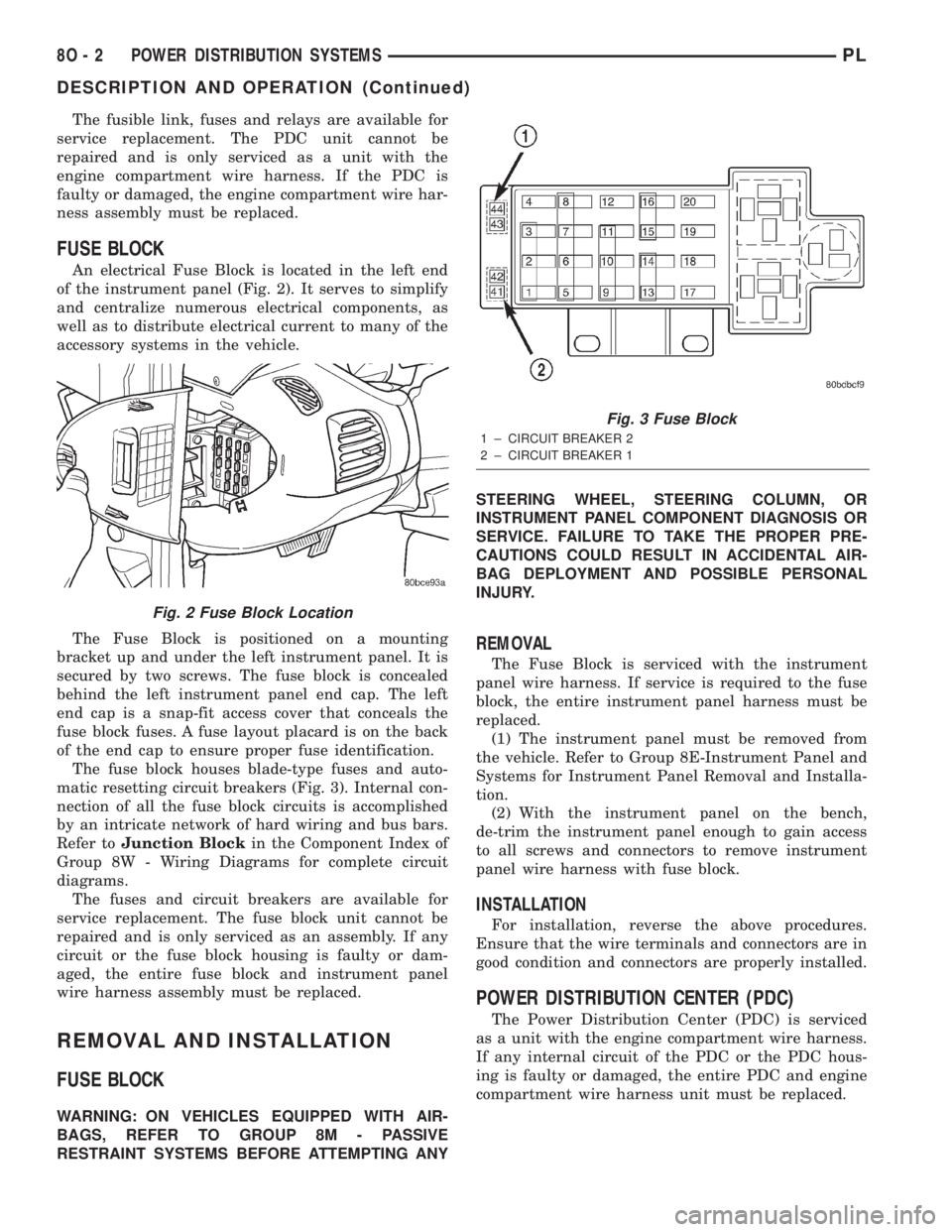
An electrical Fuse Block is located in the left end
of the instrument panel (Fig. 2). It serves to simplify
and centralize numerous electrical components, as
well as to distribute electrical current to many of the
accessory systems in the vehicle.
The Fuse Block is positioned on a mounting
bracket up and under the left instrument panel. It is
secured by two screws. The fuse block is concealed
behind the left instrument panel end cap. The left
end cap is a snap-fit access cover that conceals the
fuse block fuses. A fuse layout placard is on the back
of the end cap to ensure proper fuse identification.
The fuse block houses blade-type fuses and auto-
matic resetting circuit breakers (Fig. 3). Internal con-
nection of all the fuse block circuits is accomplished
by an intricate network of hard wiring and bus bars.
Refer toJunction Blockin the Component Index of
Group 8W - Wiring Diagrams for complete circuit
diagrams.
The fuses and circuit breakers are available for
service replacement. The fuse block unit cannot be
repaired and is only serviced as an assembly. If any
circuit or the fuse block housing is faulty or dam-
aged, the entire fuse block and instrument panel
wire harness assembly must be replaced.
REMOVAL AND INSTALLATION
FUSE BLOCK
WARNING: ON VEHICLES EQUIPPED WITH AIR-
BAGS, REFER TO GROUP 8M - PASSIVE
RESTRAINT SYSTEMS BEFORE ATTEMPTING ANYSTEERING WHEEL, STEERING COLUMN, OR
INSTRUMENT PANEL COMPONENT DIAGNOSIS OR
SERVICE. FAILURE TO TAKE THE PROPER PRE-
CAUTIONS COULD RESULT IN ACCIDENTAL AIR-
BAG DEPLOYMENT AND POSSIBLE PERSONAL
INJURY.
REMOVAL
The Fuse Block is serviced with the instrument
panel wire harness. If service is required to the fuse
block, the entire instrument panel harness must be
replaced.
(1) The instrument panel must be removed from
the vehicle. Refer to Group 8E-Instrument Panel and
Systems for Instrument Panel Removal and Installa-
tion.
(2) With the instrument panel on the bench,
de-trim the instrument panel enough to gain access
to all screws and connectors to remove instrument
panel wire harness with fuse block.
INSTALLATION
For installation, reverse the above procedures.
Ensure that the wire terminals and connectors are in
good condition and connectors are properly installed.
POWER DISTRIBUTION CENTER (PDC)
The Power Distribution Center (PDC) is serviced
as a unit with the engine compartment wire harness.
If any internal circuit of the PDC or the PDC hous-
ing is faulty or damaged, the entire PDC and engine
compartment wire harness unit must be replaced.
Fig. 2 Fuse Block Location
Fig. 3 Fuse Block
1 ± CIRCUIT BREAKER 2
2 ± CIRCUIT BREAKER 1
8O - 2 POWER DISTRIBUTION SYSTEMSPL
DESCRIPTION AND OPERATION (Continued)
Page 362 of 1285
REMOVAL
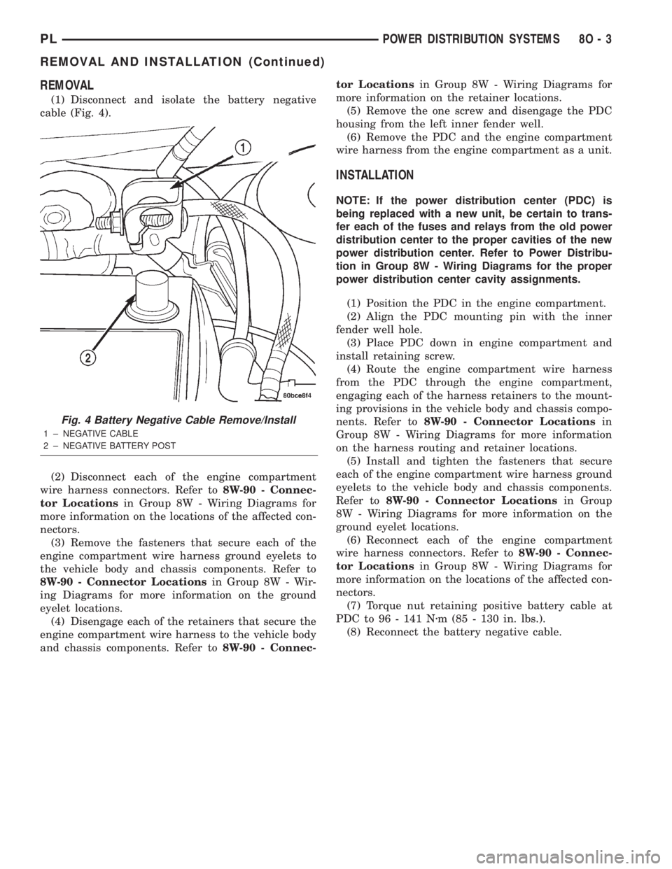
(1) Disconnect and isolate the battery negative
cable (Fig. 4).
(2) Disconnect each of the engine compartment
wire harness connectors. Refer to8W-90 - Connec-
tor Locationsin Group 8W - Wiring Diagrams for
more information on the locations of the affected con-
nectors.
(3) Remove the fasteners that secure each of the
engine compartment wire harness ground eyelets to
the vehicle body and chassis components. Refer to
8W-90 - Connector Locationsin Group 8W - Wir-
ing Diagrams for more information on the ground
eyelet locations.
(4) Disengage each of the retainers that secure the
engine compartment wire harness to the vehicle body
and chassis components. Refer to8W-90 - Connec-tor Locationsin Group 8W - Wiring Diagrams for
more information on the retainer locations.
(5) Remove the one screw and disengage the PDC
housing from the left inner fender well.
(6) Remove the PDC and the engine compartment
wire harness from the engine compartment as a unit.
INSTALLATION
NOTE: If the power distribution center (PDC) is
being replaced with a new unit, be certain to trans-
fer each of the fuses and relays from the old power
distribution center to the proper cavities of the new
power distribution center. Refer to Power Distribu-
tion in Group 8W - Wiring Diagrams for the proper
power distribution center cavity assignments.
(1) Position the PDC in the engine compartment.
(2) Align the PDC mounting pin with the inner
fender well hole.
(3) Place PDC down in engine compartment and
install retaining screw.
(4) Route the engine compartment wire harness
from the PDC through the engine compartment,
engaging each of the harness retainers to the mount-
ing provisions in the vehicle body and chassis compo-
nents. Refer to8W-90 - Connector Locationsin
Group 8W - Wiring Diagrams for more information
on the harness routing and retainer locations.
(5) Install and tighten the fasteners that secure
each of the engine compartment wire harness ground
eyelets to the vehicle body and chassis components.
Refer to8W-90 - Connector Locationsin Group
8W - Wiring Diagrams for more information on the
ground eyelet locations.
(6) Reconnect each of the engine compartment
wire harness connectors. Refer to8W-90 - Connec-
tor Locationsin Group 8W - Wiring Diagrams for
more information on the locations of the affected con-
nectors.
(7) Torque nut retaining positive battery cable at
PDC to 96 - 141 Nzm (85 - 130 in. lbs.).
(8) Reconnect the battery negative cable.
Fig. 4 Battery Negative Cable Remove/Install
1 ± NEGATIVE CABLE
2 ± NEGATIVE BATTERY POST
PLPOWER DISTRIBUTION SYSTEMS 8O - 3
REMOVAL AND INSTALLATION (Continued)
Page 364 of 1285
POWER LOCK SYSTEMS
TABLE OF CONTENTS
page page
POWER DOOR LOCKS...................... 1REMOTE KEYLESS ENTRY (RKE).............. 4
POWER DOOR LOCKS
TABLE OF CONTENTS
page page
DESCRIPTION AND OPERATION
INTRODUCTION..........................1
POWER DOOR LOCKS.....................2
CHILD PROTECTION LOCKS................2
DOOR LOCK INHIBIT.......................2
DIAGNOSIS AND TESTING
DOOR LOCK MOTOR......................2
DOOR LOCK SWITCH......................2SERVICE PROCEDURES
DOUBLE ACTIVATION UNLOCK...............3
ROLLING DOOR LOCKS....................3
REMOVAL AND INSTALLATION
DOOR LOCK MOTOR/LATCH.................3
DOOR LOCK SWITCH......................3
REMOTE KEYLESS ENTRY (RKE) MODULE.....3
DESCRIPTION AND OPERATION
INTRODUCTION
All doors can be locked or unlocked electrically by
operating the switch on either front door panel.
When the door lock switch is activated the Remote
Keyless Entry Module provides power to the door
lock motors through relays internal to the module.
The Remote Keyless Entry (RKE) Module also con-
trols the Vehicle Theft Security System (VTSS).
All doors can be locked or unlocked mechanically
and independently with their respective locking
knobs. The front doors can also be unlocked by actu-
ation of the inside remote door handle.
The RKE Module has three modes of operation
including customer usage mode, dealer lot storage
mode, and shipping mode. The customer usage mode
provides full functionality of the module and is the
mode in which the RKE module should be operating
when used by the customer. Dealer lot storage mode
and shipping modes are reduced power modes meant
to extend vehicle battery life during shipping and
storage in the dealer lot. Dealer lot storage mode pro-
vides limited VTSS and power door lock functions,
but disables the Remote Keyless Entry (RKE) func-
tions. This mode is intended to be used when the
vehicle is on the dealer lot to provide VTSS coverageof the vehicle while minimizing battery drain. Ship-
ping mode disables all normal functions (i.e. power
door locks, RKE, and VTSS) of the module, and is
intended to be used when the vehicle is shipped from
the assembly plant.
NOTE: The dealer must remove the module from
ªShip Modeº and place the RKE Module into either
the ªDealer Lotº storage or ªCustomer Usageº
modes of operation after receiving the vehicle from
the assembly plant. Refer to Group 8Q-Vehicle
Theft/Security Systems, Switching Operating
Modes/Configuring a New Module under Service
Procedures.
CENTRAL LOCKING/UNLOCKING
The door locks can be locked or unlocked electri-
cally via the exterior door key cylinders to provide
the central locking/unlocking feature. The central
locking/unlocking feature incorporates a customer
programmable ``Double activation unlockº feature
which operates in the following manner: When
enabled, the first turn of the key cylinder to the
UNLOCK position (toward the front of the vehicle)
will mechanically unlock the door whose key cylinder
is being turned. A second turn of the key cylinder to
the UNLOCK position (within five seconds of the
PLPOWER LOCK SYSTEMS 8P - 1
Page 365 of 1285
first turn) will cause all vehicle doors to unlock elec-
trically. When this feature is disabled, all vehicle
doors will be unlocked electrically upon the first turn
of a key cylinder to the UNLOCK position. The vehi-
cle is locked electrically by turning the key cylinder
to the LOCK position once, regardless of the state of
the double activation unlock feature.
POWER DOOR LOCKS
The Remote Keyless Entry (RKE) Module actuates
the power door lock relays when a door lock switch is
activated. If the door lock switch is pressed for longer
than eight consecutive seconds, the RKE module will
de-energize the door lock motors.
The system includes the rolling door locking fea-
ture. The vehicle is shipped with the system enabled.
When the system is disabled the door locks will work
by use of the door lock switches and the Remote Key-
less Entry system only. When the rolling door lock
system is enabled, the RKE module will automati-
cally lock all the vehicle doors when all of the follow-
ing conditions are met:
²All doors are closed
²The vehicle speed exceeds 15 +/- 1 mph.
²The throttle position sensor tip-in is greater
than 10 +/- 2 degrees.
The RKE module will automatically re-lock all
doors if the above conditions are met and if any of
the doors become ajar and then closed again.
The enabling/disabling of the rolling door lock fea-
ture is customer programmable, as well as program-
mable with the DRB IIItscan tool.
The power lock motors are also equipped with a
thermal protection system which prevents the motors
from burning out. The motors may chatter if they are
continuously activated.
CHILD PROTECTION LOCKS
The child protection locks are on the rear doors
only. The lock, when engaged, will disable the inside
door handle from opening the door. The lock is part
of the latch/lock assembly. The lock is engaged by
moving a lever that is located on the rearward inside
edge of the door.
DOOR LOCK INHIBIT
With the key in the ignition switch and the driver
door open, the Remote Keyless Entry (RKE) Modulewill ignore the command to lock the power door locks
via the interior driver door lock switch. Once the key
is removed, or the driver door is closed, the RKE
module will allow the power door locks to lock via the
interior door lock switches.
DIAGNOSIS AND TESTING
DOOR LOCK MOTOR
(1) Make certain battery is in normal condition
and fuses powering the RKE module aren't blown
before circuits are tested.
(2) To determine which motor is faulty, check each
individual door for electrical lock and unlock or dis-
connect the motor connectors one at a time, while
operating the door lock switch.
(3) In the event that none of the motors work, the
problem maybe caused by a shorted motor, a bad
switch or a bad relay internal to the RKE module.
Disconnecting a defective motor will allow the others
to work.
(4) To test an individual door lock motor, discon-
nect the electrical connector from the motor.
(5) To lock the door, connect a 12 volt power source
to one pin of the lock motor and a ground wire to the
other pin.
(6) To unlock the door, reverse the wire connec-
tions at the motor pin terminals.
(7) If these results are NOT obtained, replace the
motor.
DOOR LOCK SWITCH
(1) Remove the switch from its mounting location,
and disconnect from vehicle wiring harness. Refer to
Door Lock Switch Removal and Installation in this
section.
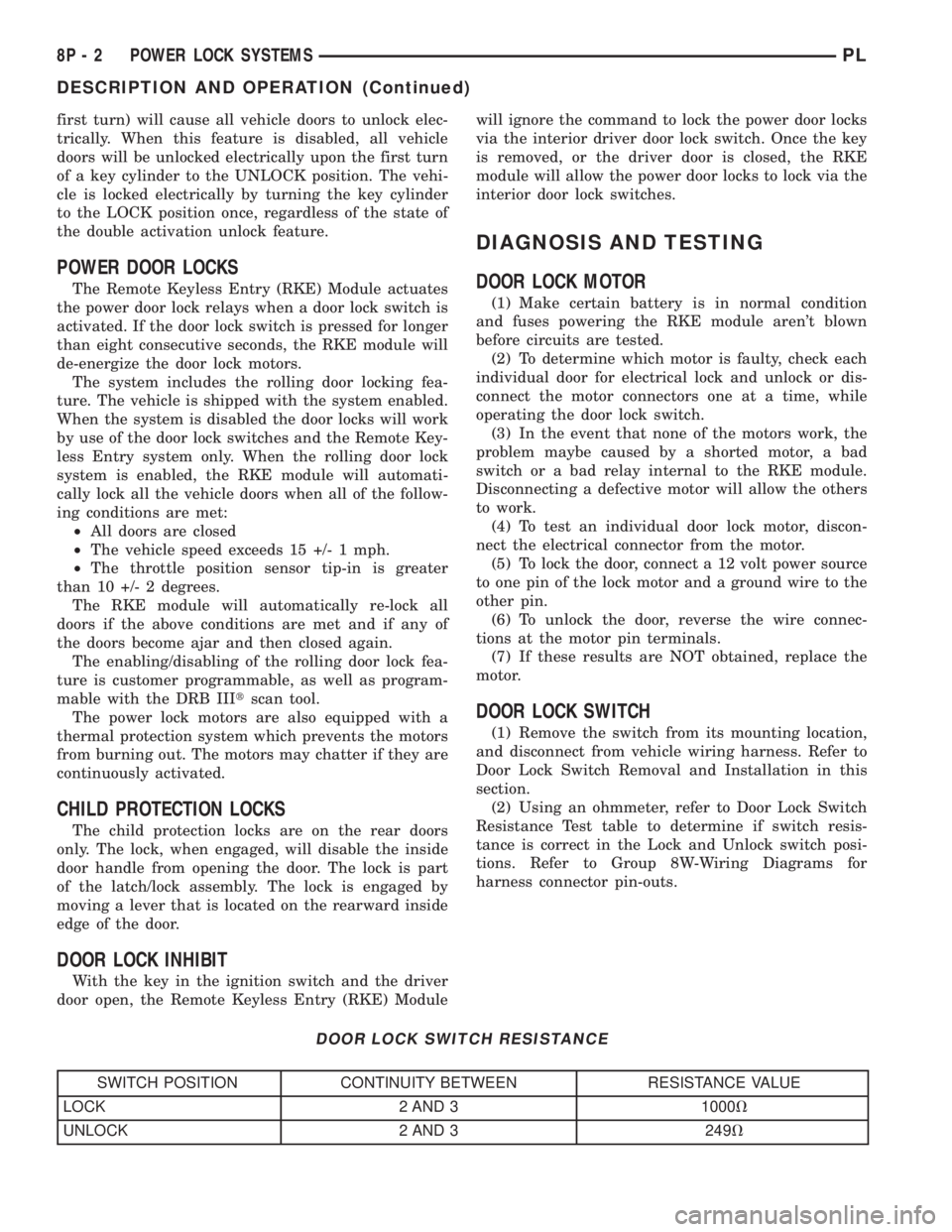
(2) Using an ohmmeter, refer to Door Lock Switch
Resistance Test table to determine if switch resis-
tance is correct in the Lock and Unlock switch posi-
tions. Refer to Group 8W-Wiring Diagrams for
harness connector pin-outs.
DOOR LOCK SWITCH RESISTANCE
SWITCH POSITION CONTINUITY BETWEEN RESISTANCE VALUE
LOCK 2 AND 3 1000V
UNLOCK 2 AND 3 249V
8P - 2 POWER LOCK SYSTEMSPL
DESCRIPTION AND OPERATION (Continued)
Page 386 of 1285
POWER MIRRORS
TABLE OF CONTENTS
page page
GENERAL INFORMATION
INTRODUCTION..........................1
DIAGNOSIS AND TESTING
POWER FOLD AWAY MIRROR SWITCH TEST...1POWER FOLD AWAY MIRROR MOTOR........1
REMOVAL AND INSTALLATION
POWER FOLD-AWAY MIRROR SWITCH.......1
POWER FOLD-AWAY MIRROR...............2
GENERAL INFORMATION
INTRODUCTION
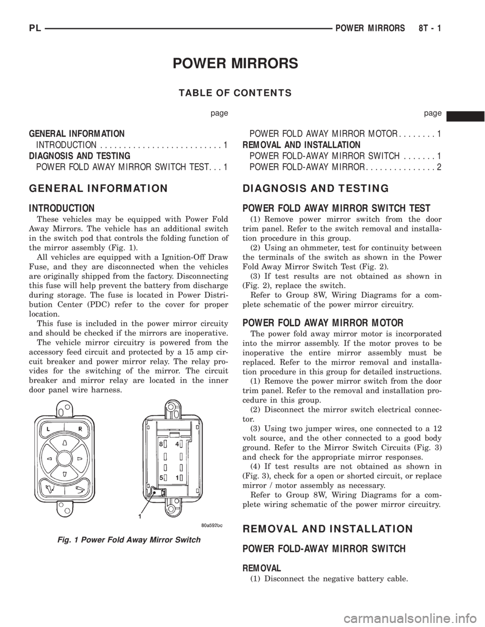
These vehicles may be equipped with Power Fold
Away Mirrors. The vehicle has an additional switch
in the switch pod that controls the folding function of
the mirror assembly (Fig. 1).
All vehicles are equipped with a Ignition-Off Draw
Fuse, and they are disconnected when the vehicles
are originally shipped from the factory. Disconnecting
this fuse will help prevent the battery from discharge
during storage. The fuse is located in Power Distri-
bution Center (PDC) refer to the cover for proper
location.
This fuse is included in the power mirror circuity
and should be checked if the mirrors are inoperative.
The vehicle mirror circuitry is powered from the
accessory feed circuit and protected by a 15 amp cir-
cuit breaker and power mirror relay. The relay pro-
vides for the switching of the mirror. The circuit
breaker and mirror relay are located in the inner
door panel wire harness.
DIAGNOSIS AND TESTING
POWER FOLD AWAY MIRROR SWITCH TEST
(1) Remove power mirror switch from the door
trim panel. Refer to the switch removal and installa-
tion procedure in this group.
(2) Using an ohmmeter, test for continuity between
the terminals of the switch as shown in the Power
Fold Away Mirror Switch Test (Fig. 2).
(3) If test results are not obtained as shown in
(Fig. 2), replace the switch.
Refer to Group 8W, Wiring Diagrams for a com-
plete schematic of the power mirror circuitry.
POWER FOLD AWAY MIRROR MOTOR
The power fold away mirror motor is incorporated
into the mirror assembly. If the motor proves to be
inoperative the entire mirror assembly must be
replaced. Refer to the mirror removal and installa-
tion procedure in this group for detailed instructions.
(1) Remove the power mirror switch from the door
trim panel. Refer to the removal and installation pro-
cedure in this group.
(2) Disconnect the mirror switch electrical connec-
tor.
(3) Using two jumper wires, one connected to a 12
volt source, and the other connected to a good body
ground. Refer to the Mirror Switch Circuits (Fig. 3)
and check for the appropriate mirror responses.
(4) If test results are not obtained as shown in
(Fig. 3), check for a open or shorted circuit, or replace
mirror / motor assembly as necessary.
Refer to Group 8W, Wiring Diagrams for a com-
plete wiring schematic of the power mirror circuitry.
REMOVAL AND INSTALLATION
POWER FOLD-AWAY MIRROR SWITCH
REMOVAL
(1) Disconnect the negative battery cable.
Fig. 1 Power Fold Away Mirror Switch
PLPOWER MIRRORS 8T - 1
Page 398 of 1285
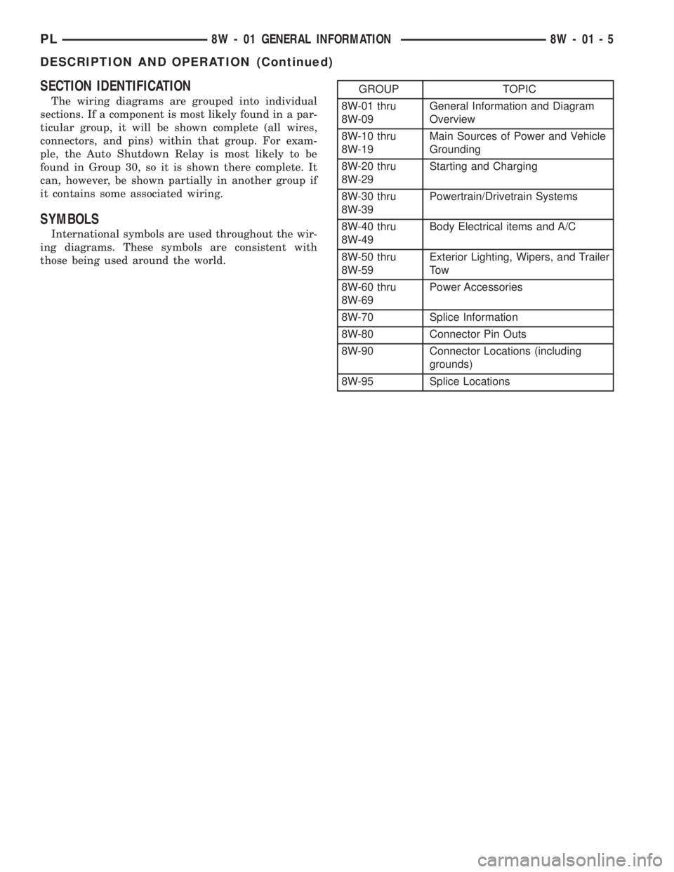
SECTION IDENTIFICATION
The wiring diagrams are grouped into individual
sections. If a component is most likely found in a par-
ticular group, it will be shown complete (all wires,
connectors, and pins) within that group. For exam-
ple, the Auto Shutdown Relay is most likely to be
found in Group 30, so it is shown there complete. It
can, however, be shown partially in another group if
it contains some associated wiring.
SYMBOLS
International symbols are used throughout the wir-
ing diagrams. These symbols are consistent with
those being used around the world.
GROUP TOPIC
8W-01 thru
8W-09General Information and Diagram
Overview
8W-10 thru
8W-19Main Sources of Power and Vehicle
Grounding
8W-20 thru
8W-29Starting and Charging
8W-30 thru
8W-39Powertrain/Drivetrain Systems
8W-40 thru
8W-49Body Electrical items and A/C
8W-50 thru
8W-59Exterior Lighting, Wipers, and Trailer
To w
8W-60 thru
8W-69Power Accessories
8W-70 Splice Information
8W-80 Connector Pin Outs
8W-90 Connector Locations (including
grounds)
8W-95 Splice Locations
PL8W - 01 GENERAL INFORMATION 8W - 01 - 5
DESCRIPTION AND OPERATION (Continued)
Page 401 of 1285
WARNING: DO NOT ALLOW FLAME OR SPARKS
NEAR THE BATTERY. GASES ARE ALWAYS
PRESENT IN AND AROUND THE BATTERY.
WARNING: ALWAYS REMOVE RINGS, WATCHES,
LOOSE HANGING JEWELRY, AND LOOSE CLOTH-
ING.
TAKE OUTS
The abbreviation T/O is used in the component
location section to indicate a point in which the wir-
ing harness branches out to a component.
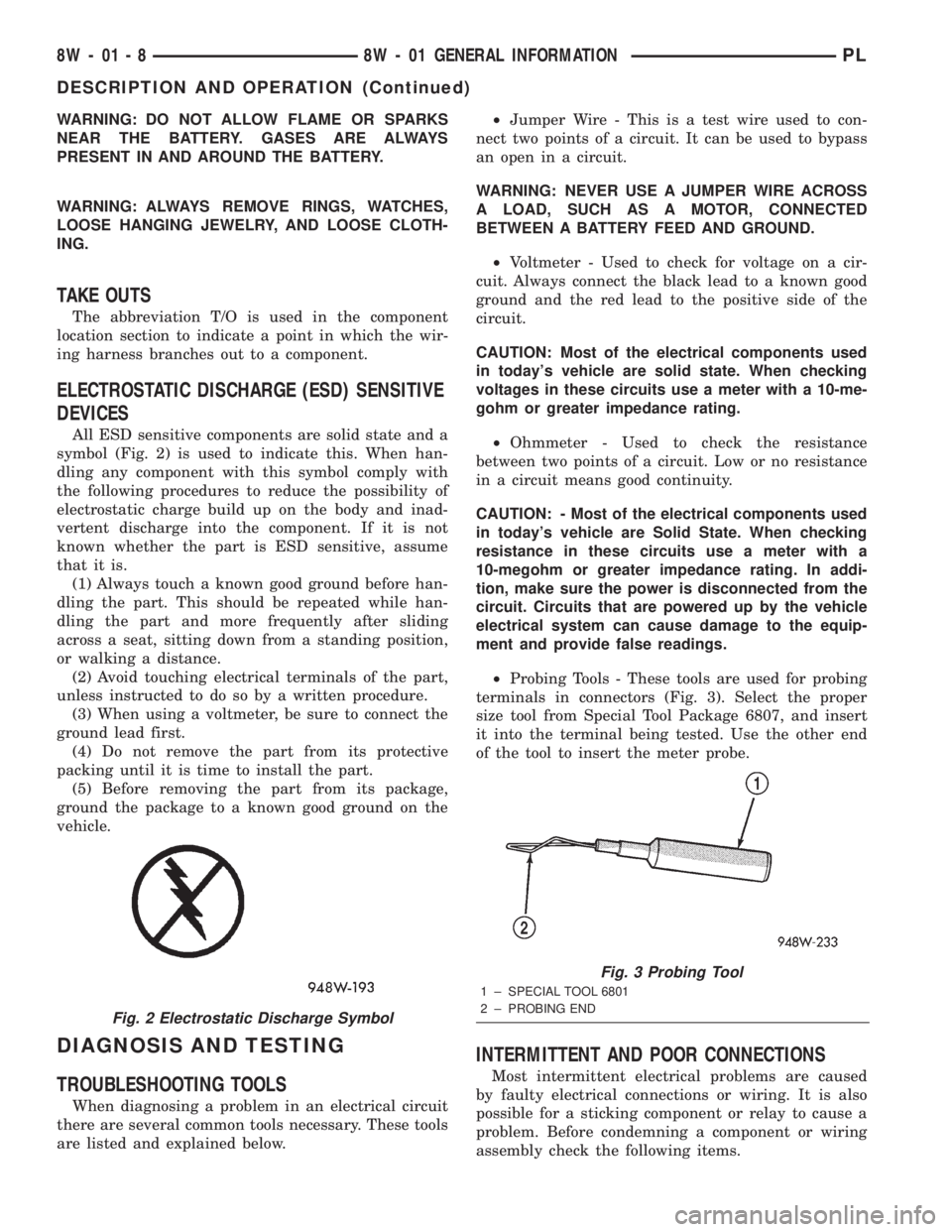
ELECTROSTATIC DISCHARGE (ESD) SENSITIVE
DEVICES
All ESD sensitive components are solid state and a
symbol (Fig. 2) is used to indicate this. When han-
dling any component with this symbol comply with
the following procedures to reduce the possibility of
electrostatic charge build up on the body and inad-
vertent discharge into the component. If it is not
known whether the part is ESD sensitive, assume
that it is.
(1) Always touch a known good ground before han-
dling the part. This should be repeated while han-
dling the part and more frequently after sliding
across a seat, sitting down from a standing position,
or walking a distance.
(2) Avoid touching electrical terminals of the part,
unless instructed to do so by a written procedure.
(3) When using a voltmeter, be sure to connect the
ground lead first.
(4) Do not remove the part from its protective
packing until it is time to install the part.
(5) Before removing the part from its package,
ground the package to a known good ground on the
vehicle.
DIAGNOSIS AND TESTING
TROUBLESHOOTING TOOLS
When diagnosing a problem in an electrical circuit
there are several common tools necessary. These tools
are listed and explained below.²Jumper Wire - This is a test wire used to con-
nect two points of a circuit. It can be used to bypass
an open in a circuit.
WARNING: NEVER USE A JUMPER WIRE ACROSS
A LOAD, SUCH AS A MOTOR, CONNECTED
BETWEEN A BATTERY FEED AND GROUND.
²Voltmeter - Used to check for voltage on a cir-
cuit. Always connect the black lead to a known good
ground and the red lead to the positive side of the
circuit.
CAUTION: Most of the electrical components used
in today's vehicle are solid state. When checking
voltages in these circuits use a meter with a 10-me-
gohm or greater impedance rating.
²Ohmmeter - Used to check the resistance
between two points of a circuit. Low or no resistance
in a circuit means good continuity.
CAUTION: - Most of the electrical components used
in today's vehicle are Solid State. When checking
resistance in these circuits use a meter with a
10-megohm or greater impedance rating. In addi-
tion, make sure the power is disconnected from the
circuit. Circuits that are powered up by the vehicle
electrical system can cause damage to the equip-
ment and provide false readings.
²Probing Tools - These tools are used for probing
terminals in connectors (Fig. 3). Select the proper
size tool from Special Tool Package 6807, and insert
it into the terminal being tested. Use the other end
of the tool to insert the meter probe.
INTERMITTENT AND POOR CONNECTIONS
Most intermittent electrical problems are caused
by faulty electrical connections or wiring. It is also
possible for a sticking component or relay to cause a
problem. Before condemning a component or wiring
assembly check the following items.
Fig. 2 Electrostatic Discharge Symbol
Fig. 3 Probing Tool
1 ± SPECIAL TOOL 6801
2 ± PROBING END
8W - 01 - 8 8W - 01 GENERAL INFORMATIONPL
DESCRIPTION AND OPERATION (Continued)