2000 DODGE NEON tire type
[x] Cancel search: tire typePage 403 of 1285
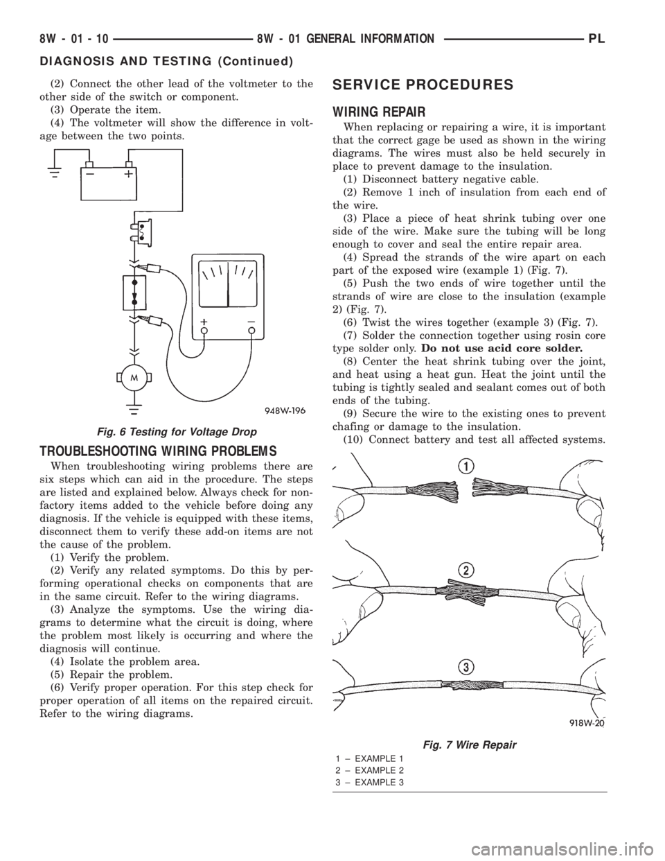
(2) Connect the other lead of the voltmeter to the
other side of the switch or component.
(3) Operate the item.
(4) The voltmeter will show the difference in volt-
age between the two points.
TROUBLESHOOTING WIRING PROBLEMS
When troubleshooting wiring problems there are
six steps which can aid in the procedure. The steps
are listed and explained below. Always check for non-
factory items added to the vehicle before doing any
diagnosis. If the vehicle is equipped with these items,
disconnect them to verify these add-on items are not
the cause of the problem.
(1) Verify the problem.
(2) Verify any related symptoms. Do this by per-
forming operational checks on components that are
in the same circuit. Refer to the wiring diagrams.
(3) Analyze the symptoms. Use the wiring dia-
grams to determine what the circuit is doing, where
the problem most likely is occurring and where the
diagnosis will continue.
(4) Isolate the problem area.
(5) Repair the problem.
(6) Verify proper operation. For this step check for
proper operation of all items on the repaired circuit.
Refer to the wiring diagrams.
SERVICE PROCEDURES
WIRING REPAIR
When replacing or repairing a wire, it is important
that the correct gage be used as shown in the wiring
diagrams. The wires must also be held securely in
place to prevent damage to the insulation.
(1) Disconnect battery negative cable.
(2) Remove 1 inch of insulation from each end of
the wire.
(3) Place a piece of heat shrink tubing over one
side of the wire. Make sure the tubing will be long
enough to cover and seal the entire repair area.
(4) Spread the strands of the wire apart on each
part of the exposed wire (example 1) (Fig. 7).
(5) Push the two ends of wire together until the
strands of wire are close to the insulation (example
2) (Fig. 7).
(6) Twist the wires together (example 3) (Fig. 7).
(7) Solder the connection together using rosin core
type solder only.Do not use acid core solder.
(8) Center the heat shrink tubing over the joint,
and heat using a heat gun. Heat the joint until the
tubing is tightly sealed and sealant comes out of both
ends of the tubing.
(9) Secure the wire to the existing ones to prevent
chafing or damage to the insulation.
(10) Connect battery and test all affected systems.
Fig. 6 Testing for Voltage Drop
Fig. 7 Wire Repair
1 ± EXAMPLE 1
2 ± EXAMPLE 2
3 ± EXAMPLE 3
8W - 01 - 10 8W - 01 GENERAL INFORMATIONPL
DIAGNOSIS AND TESTING (Continued)
Page 406 of 1285
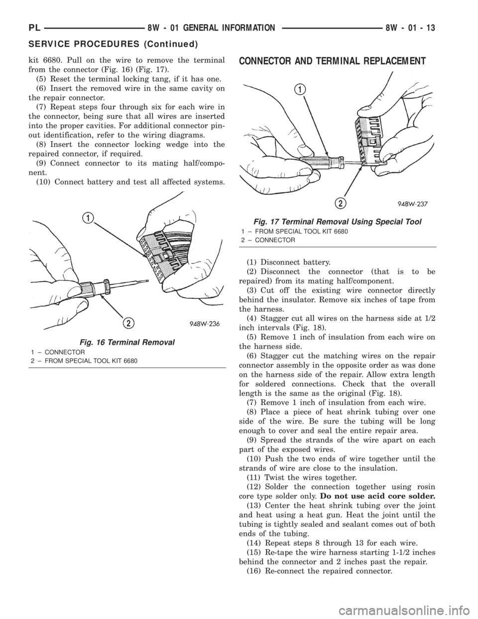
kit 6680. Pull on the wire to remove the terminal
from the connector (Fig. 16) (Fig. 17).
(5) Reset the terminal locking tang, if it has one.
(6) Insert the removed wire in the same cavity on
the repair connector.
(7) Repeat steps four through six for each wire in
the connector, being sure that all wires are inserted
into the proper cavities. For additional connector pin-
out identification, refer to the wiring diagrams.
(8) Insert the connector locking wedge into the
repaired connector, if required.
(9) Connect connector to its mating half/compo-
nent.
(10) Connect battery and test all affected systems.CONNECTOR AND TERMINAL REPLACEMENT
(1) Disconnect battery.
(2) Disconnect the connector (that is to be
repaired) from its mating half/component.
(3) Cut off the existing wire connector directly
behind the insulator. Remove six inches of tape from
the harness.
(4) Stagger cut all wires on the harness side at 1/2
inch intervals (Fig. 18).
(5) Remove 1 inch of insulation from each wire on
the harness side.
(6) Stagger cut the matching wires on the repair
connector assembly in the opposite order as was done
on the harness side of the repair. Allow extra length
for soldered connections. Check that the overall
length is the same as the original (Fig. 18).
(7) Remove 1 inch of insulation from each wire.
(8) Place a piece of heat shrink tubing over one
side of the wire. Be sure the tubing will be long
enough to cover and seal the entire repair area.
(9) Spread the strands of the wire apart on each
part of the exposed wires.
(10) Push the two ends of wire together until the
strands of wire are close to the insulation.
(11) Twist the wires together.
(12) Solder the connection together using rosin
core type solder only.Do not use acid core solder.
(13) Center the heat shrink tubing over the joint
and heat using a heat gun. Heat the joint until the
tubing is tightly sealed and sealant comes out of both
ends of the tubing.
(14) Repeat steps 8 through 13 for each wire.
(15) Re-tape the wire harness starting 1-1/2 inches
behind the connector and 2 inches past the repair.
(16) Re-connect the repaired connector.
Fig. 16 Terminal Removal
1 ± CONNECTOR
2 ± FROM SPECIAL TOOL KIT 6680
Fig. 17 Terminal Removal Using Special Tool
1 ± FROM SPECIAL TOOL KIT 6680
2 ± CONNECTOR
PL8W - 01 GENERAL INFORMATION 8W - 01 - 13
SERVICE PROCEDURES (Continued)
Page 874 of 1285
POWER STEERING FLUID PRESSURE SWITCH
A power steering pressure switch is used to
improve the vehicle's idle quality. The pressure
switch improves vehicle idle quality by causing a
readjustment of the engine idle speed as necessary
when increased fluid pressure is sensed in the power
steering system.
The pressure switch functions by signaling the
powertrain control module that an increase in pres-
sure of the power steering system is putting addi-
tional load on the engine. This type of condition
exists when the front tires of the vehicle are turned
while the vehicle is stationary and the engine is at
idle speed. When the powertrain control module
receives the signal from the power steering pressure
switch, it directs the engine to increase its idle speed.
This increase in engine idle speed compensates for
the additional load, thus maintaining the required
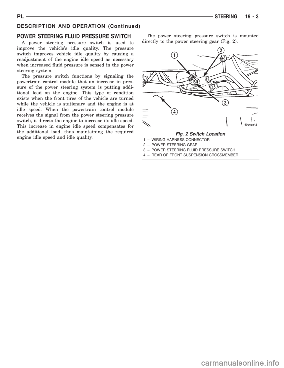
engine idle speed and idle quality.The power steering pressure switch is mounted
directly to the power steering gear (Fig. 2).
Fig. 2 Switch Location
1 ± WIRING HARNESS CONNECTOR
2 ± POWER STEERING GEAR
3 ± POWER STEERING FLUID PRESSURE SWITCH
4 ± REAR OF FRONT SUSPENSION CROSSMEMBER
PLSTEERING 19 - 3
DESCRIPTION AND OPERATION (Continued)
Page 877 of 1285
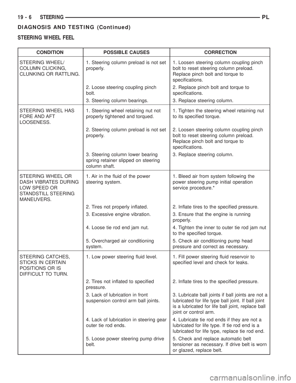
STEERING WHEEL FEEL
CONDITION POSSIBLE CAUSES CORRECTION
STEERING WHEEL/
COLUMN CLICKING,
CLUNKING OR RATTLING.1. Steering column preload is not set
properly.1. Loosen steering column coupling pinch
bolt to reset steering column preload.
Replace pinch bolt and torque to
specifications.
2. Loose steering coupling pinch
bolt.2. Replace pinch bolt and torque to
specifications.
3. Steering column bearings. 3. Replace steering column.
STEERING WHEEL HAS
FORE AND AFT
LOOSENESS.1. Steering wheel retaining nut not
properly tightened and torqued.1. Tighten the steering wheel retaining nut
to its specified torque.
2. Steering column preload is not set
properly.2. Loosen steering column coupling pinch
bolt to reset steering column preload.
Replace pinch bolt and torque to
specifications.
3. Steering column lower bearing
spring retainer slipped on steering
column shaft.3. Replace steering column.
STEERING WHEEL OR
DASH VIBRATES DURING
LOW SPEED OR
STANDSTILL STEERING
MANEUVERS.1. Air in the fluid of the power
steering system.1. Bleed air from system following the
power steering pump initial operation
service procedure.*
2. Tires not properly inflated. 2. Inflate tires to the specified pressure.
3. Excessive engine vibration. 3. Ensure that the engine is running
properly.
4. Loose tie rod end jam nut. 4. Tighten the inner to outer tie rod jam nut
to the specified torque.
5. Overcharged air conditioning
system.5. Check air conditioning pump head
pressure and correct as necessary.
STEERING CATCHES,
STICKS IN CERTAIN
POSITIONS OR IS
DIFFICULT TO TURN.1. Low power steering fluid level. 1. Fill power steering fluid reservoir to
specified level and check for leaks.
2. Tires not inflated to specified
pressure.2. Inflate tires to the specified pressure.
3. Lack of lubrication in front
suspension control arm ball joints.3. Lubricate ball joints if ball joints are not a
lubricated for life type ball joint. If ball joint
is a lubricated for life ball joint, replace ball
joint or control arm.
4. Lack of lubrication in steering gear
outer tie rod ends.4. Lubricate tie rod ends if they are not a
lubricated for life type. If tie rod end is a
lubricated for life type, replace tie rod end.
5. Loose power steering pump drive
belt.5. Check and replace automatic belt
tensioner as necessary. If drive belt is worn
or glazed, replace belt.
19 - 6 STEERINGPL
DIAGNOSIS AND TESTING (Continued)
Page 878 of 1285
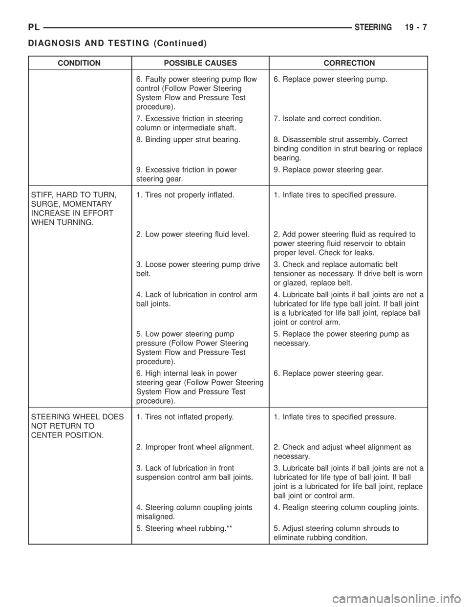
CONDITION POSSIBLE CAUSES CORRECTION
6. Faulty power steering pump flow
control (Follow Power Steering
System Flow and Pressure Test
procedure).6. Replace power steering pump.
7. Excessive friction in steering
column or intermediate shaft.7. Isolate and correct condition.
8. Binding upper strut bearing. 8. Disassemble strut assembly. Correct
binding condition in strut bearing or replace
bearing.
9. Excessive friction in power
steering gear.9. Replace power steering gear.
STIFF, HARD TO TURN,
SURGE, MOMENTARY
INCREASE IN EFFORT
WHEN TURNING.1. Tires not properly inflated. 1. Inflate tires to specified pressure.
2. Low power steering fluid level. 2. Add power steering fluid as required to
power steering fluid reservoir to obtain
proper level. Check for leaks.
3. Loose power steering pump drive
belt.3. Check and replace automatic belt
tensioner as necessary. If drive belt is worn
or glazed, replace belt.
4. Lack of lubrication in control arm
ball joints.4. Lubricate ball joints if ball joints are not a
lubricated for life type ball joint. If ball joint
is a lubricated for life ball joint, replace ball
joint or control arm.
5. Low power steering pump
pressure (Follow Power Steering
System Flow and Pressure Test
procedure).5. Replace the power steering pump as
necessary.
6. High internal leak in power
steering gear (Follow Power Steering
System Flow and Pressure Test
procedure).6. Replace power steering gear.
STEERING WHEEL DOES
NOT RETURN TO
CENTER POSITION.1. Tires not inflated properly. 1. Inflate tires to specified pressure.
2. Improper front wheel alignment. 2. Check and adjust wheel alignment as
necessary.
3. Lack of lubrication in front
suspension control arm ball joints.3. Lubricate ball joints if ball joints are not a
lubricated for life type of ball joint. If ball
joint is a lubricated for life ball joint, replace
ball joint or control arm.
4. Steering column coupling joints
misaligned.4. Realign steering column coupling joints.
5. Steering wheel rubbing.** 5. Adjust steering column shrouds to
eliminate rubbing condition.
PLSTEERING 19 - 7
DIAGNOSIS AND TESTING (Continued)
Page 893 of 1285
NOTE: The power steering gear should not be ser-
viced or adjusted. If a malfunction or oil leak occurs
with the steering gear, the complete steering gear
needs to be replaced.
REMOVAL AND INSTALLATION
SERVICE WARNINGS AND CAUTIONS
WARNING: POWER STEERING FLUID, ENGINE
PARTS AND EXHAUST SYSTEM MAY BE
EXTREMELY HOT IF ENGINE HAS BEEN RUNNING.
DO NOT START ENGINE WITH ANY LOOSE OR DIS-
CONNECTED HOSES. DO NOT ALLOW HOSES TO
TOUCH HOT EXHAUST MANIFOLD OR CATALYST.
WARNING: FLUID LEVEL SHOULD BE CHECKED
WITH THE ENGINE OFF TO PREVENT PERSONAL
INJURY FROM MOVING PARTS.
CAUTION: When the system is open, cap all open
ends of the hoses, power steering pump fittings or
power steering gear ports to prevent entry of for-
eign material into the components.
NOTE: Do not use any type of automatic transmis-
sion fluid in the power steering system.
POWER STEERING GEAR
NOTE: Before proceeding with this removal and
installation procedure, review SERVICE WARNINGS
AND CAUTIONS at the beginning of REMOVAL AND
INSTALLATION in this section.
REMOVAL
(1) Place the steering wheel in the STRAIGHT-
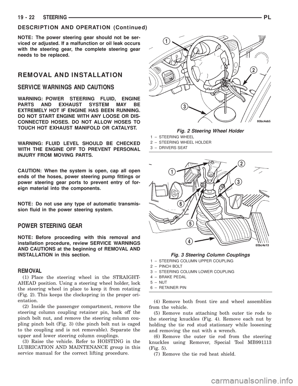
AHEAD position. Using a steering wheel holder, lock
the steering wheel in place to keep it from rotating
(Fig. 2). This keeps the clockspring in the proper ori-
entation.
(2) Inside the passenger compartment, remove the
steering column coupling retainer pin, back off the
pinch bolt nut, and remove the steering column cou-
pling pinch bolt (Fig. 3) (the pinch bolt nut is caged
to the coupling and is not removable). Separate the
upper and lower steering column couplings.
(3) Raise the vehicle. Refer to HOISTING in the
LUBRICATION AND MAINTENANCE group in this
service manual for the correct lifting procedure.(4) Remove both front tire and wheel assemblies
from the vehicle.
(5) Remove nuts attaching both outer tie rods to
the steering knuckles (Fig. 4). Remove each nut by
holding the tie rod stud stationary while loosening
and removing the nut with a wrench.
(6) Remove the outer tie rod from the steering
knuckles using Remover, Special Tool MB991113
(Fig. 5).
(7) Remove the tie rod heat shield.
Fig. 2 Steering Wheel Holder
1 ± STEERING WHEEL
2 ± STEERING WHEEL HOLDER
3 ± DRIVERS SEAT
Fig. 3 Steering Column Couplings
1 ± STEERING COLUMN UPPER COUPLING
2 ± PINCH BOLT
3 ± STEERING COLUMN LOWER COUPLING
4 ± BRAKE PEDAL
5 ± NUT
6 ± RETAINER PIN
19 - 22 STEERINGPL
DESCRIPTION AND OPERATION (Continued)
Page 1071 of 1285
TIRE IDENTIFICATION
Tire type, size, aspect ratio and speed rating are
encoded in the letters and numbers imprinted on the
side wall of the tire. Refer to the chart to decipher
the tire identification code (Fig. 2).
Performance tires will have a speed rating letter
after the aspect ratio number. For example, the letter
ªSº indicates that the tire is speed rated up to 112
mph (180 km/h). The speed rating is not always
printed on the tire sidewall.
²Q -up to 100 mph (160 km/h)
²T -up to 118 mph (190 km/h)
²U -up to 124 mph (200 km/h)
²H -up to 130 mph (210 km/h)
²V -up to 149 mph (240 km/h)
²Z -more than 149 mph (240 km/h) (consult the
tire manufacturer for the specific speed rating)
An All Season type tire will have eitherM+S,M
& S or M-S (indicating mud and snow traction)
imprinted on the side wall.
TIRE CHAINS
Refer to the owners manual supplied with the vehi-
cle to determine whether the use of tire chains is per-
mitted on this vehicle.
RADIAL-PLY TIRES
Radial-ply tires improve handling, tread life and
ride quality, and decrease rolling resistance.
Radial-ply tires must always be used in sets of
four. Under no circumstances should they be used on
the front only. They may be mixed with temporary
spare tires when necessary. A maximum speed of 50
MPH is recommended while a temporary spare is in
use.
Radial-ply tires have the same load-carrying capac-
ity as other types of tires of the same size. They also
use the same recommended inflation pressures.
The use of oversized tires, either in the front or
rear of the vehicle, can cause vehicle drive train fail-
ure. This could also cause inaccurate wheel speed
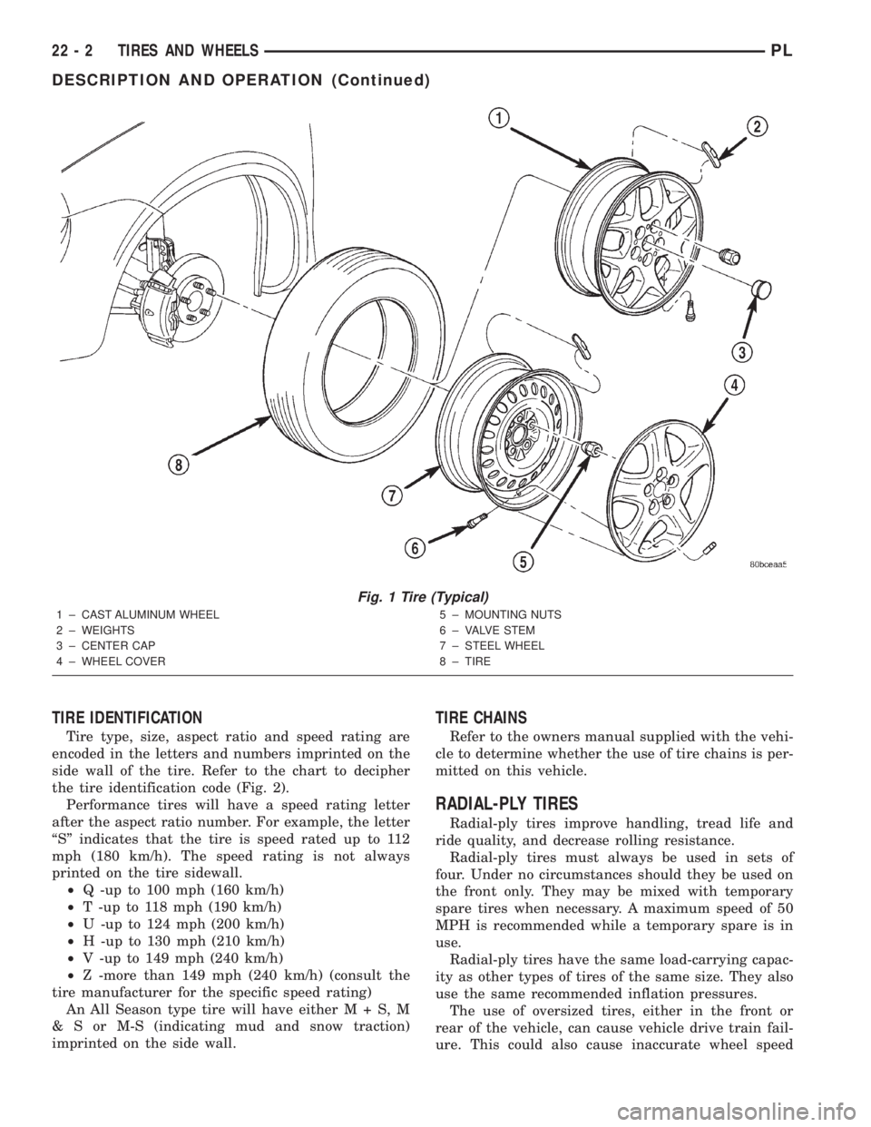
Fig. 1 Tire (Typical)
1 ± CAST ALUMINUM WHEEL
2 ± WEIGHTS
3 ± CENTER CAP
4 ± WHEEL COVER5 ± MOUNTING NUTS
6 ± VALVE STEM
7 ± STEEL WHEEL
8 ± TIRE
22 - 2 TIRES AND WHEELSPL
DESCRIPTION AND OPERATION (Continued)
Page 1080 of 1285
sections help hold the tire in position on the wheel
until the vehicle can be brought to a safe stop.
Cast aluminum wheels require special balance
weights to fit on the thicker flange of the rim and
special wheel clamps for the alignment equipment.
The wheel studs and nuts are designed for specific
wheel applications and must be replaced with equiv-
alent parts. Do not use replacement parts of lesser
quality or of a substitute design. All aluminum
wheels use wheel nuts with an enlarged nose. This
enlarged nose is necessary to ensure proper retention
of the wheels.
Vehicles that are equipped with lock-on wheel cov-
ers use large nose wheel nuts. The wheel nuts are
externally threaded so that the wheel covers can be
attached to the wheel nuts.
WHEEL COVER (LOCK-ON)
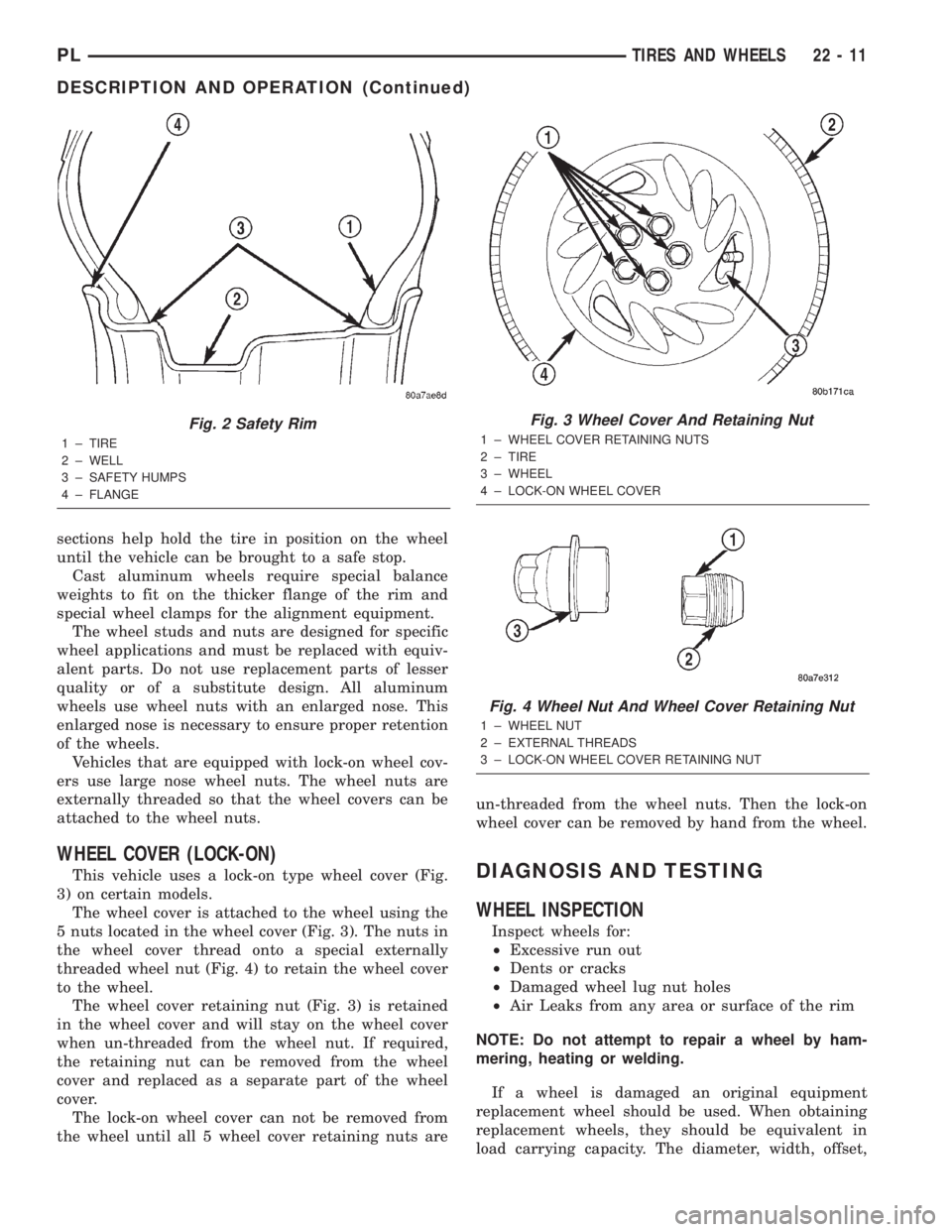
This vehicle uses a lock-on type wheel cover (Fig.
3) on certain models.
The wheel cover is attached to the wheel using the
5 nuts located in the wheel cover (Fig. 3). The nuts in
the wheel cover thread onto a special externally
threaded wheel nut (Fig. 4) to retain the wheel cover
to the wheel.
The wheel cover retaining nut (Fig. 3) is retained
in the wheel cover and will stay on the wheel cover
when un-threaded from the wheel nut. If required,
the retaining nut can be removed from the wheel
cover and replaced as a separate part of the wheel
cover.
The lock-on wheel cover can not be removed from
the wheel until all 5 wheel cover retaining nuts areun-threaded from the wheel nuts. Then the lock-on
wheel cover can be removed by hand from the wheel.DIAGNOSIS AND TESTING
WHEEL INSPECTION
Inspect wheels for:
²Excessive run out
²Dents or cracks
²Damaged wheel lug nut holes
²Air Leaks from any area or surface of the rim
NOTE: Do not attempt to repair a wheel by ham-
mering, heating or welding.
If a wheel is damaged an original equipment
replacement wheel should be used. When obtaining
replacement wheels, they should be equivalent in
load carrying capacity. The diameter, width, offset,
Fig. 2 Safety Rim
1 ± TIRE
2 ± WELL
3 ± SAFETY HUMPS
4 ± FLANGE
Fig. 3 Wheel Cover And Retaining Nut
1 ± WHEEL COVER RETAINING NUTS
2 ± TIRE
3 ± WHEEL
4 ± LOCK-ON WHEEL COVER
Fig. 4 Wheel Nut And Wheel Cover Retaining Nut
1 ± WHEEL NUT
2 ± EXTERNAL THREADS
3 ± LOCK-ON WHEEL COVER RETAINING NUT
PLTIRES AND WHEELS 22 - 11
DESCRIPTION AND OPERATION (Continued)