2000 DODGE NEON tire type
[x] Cancel search: tire typePage 1137 of 1285

SAFETY PRECAUTION AND WARNINGS
WARNING: EYE PROTECTION SHOULD BE USED
WHEN SERVICING RTM AND SMC COMPONENTS.
PERSONAL INJURE CAN RESULT.
USE AN OSHA APPROVED BREATHING DEVICE
WHEN MIXING EPOXY, GRINDING RTM AND SMC,
AND SPRAYING PAINT OR SOLVENTS IN A CON-
FINED AREA. PERSONAL INJURY CAN RESULT.
AVOID PROLONGED SKIN CONTACT WITH
EPOXY RESIN, PETROLEUM, OR ALCOHOL BASED
SOLVENTS. PERSONAL INJURY CAN RESULT.
DO NOT VENTURE UNDER A HOISTED VEHICLE
THAT IS NOT PROPERLY SUPPORTED ON SAFETY
STANDS. PERSONAL INJURY CAN RESULT.
²When holes must be drilled or cut in body pan-
els, verify locations of internal body components and
electrical wiring. Damage to vehicle can result.
²Do not use abrasive chemicals or compounds on
undamaged painted surfaces around repair areas.
Damage to finish can result.
PANEL SECTIONING
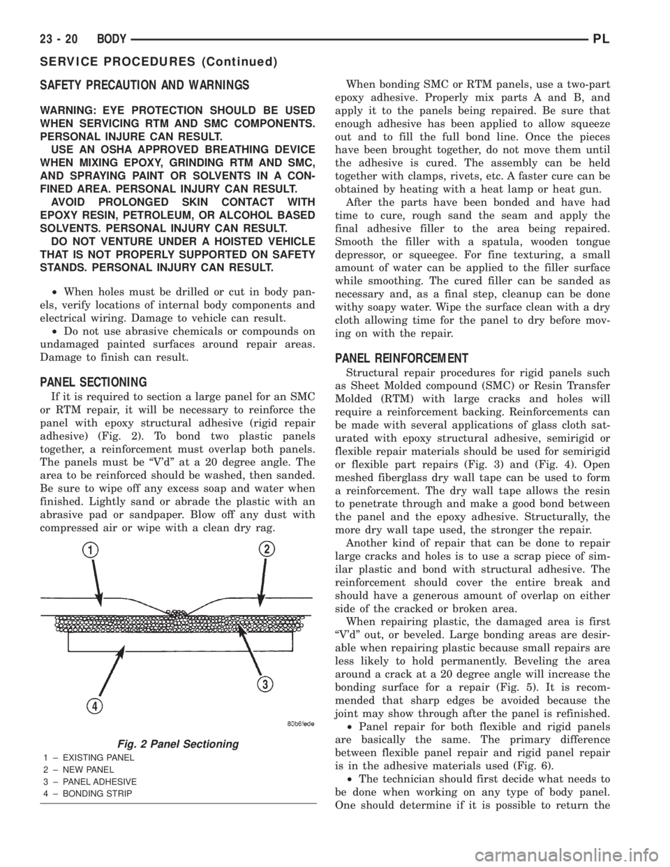
If it is required to section a large panel for an SMC
or RTM repair, it will be necessary to reinforce the
panel with epoxy structural adhesive (rigid repair
adhesive) (Fig. 2). To bond two plastic panels
together, a reinforcement must overlap both panels.
The panels must be ªV'dº at a 20 degree angle. The
area to be reinforced should be washed, then sanded.
Be sure to wipe off any excess soap and water when
finished. Lightly sand or abrade the plastic with an
abrasive pad or sandpaper. Blow off any dust with
compressed air or wipe with a clean dry rag.When bonding SMC or RTM panels, use a two-part
epoxy adhesive. Properly mix parts A and B, and
apply it to the panels being repaired. Be sure that
enough adhesive has been applied to allow squeeze
out and to fill the full bond line. Once the pieces
have been brought together, do not move them until
the adhesive is cured. The assembly can be held
together with clamps, rivets, etc. A faster cure can be
obtained by heating with a heat lamp or heat gun.
After the parts have been bonded and have had
time to cure, rough sand the seam and apply the
final adhesive filler to the area being repaired.
Smooth the filler with a spatula, wooden tongue
depressor, or squeegee. For fine texturing, a small
amount of water can be applied to the filler surface
while smoothing. The cured filler can be sanded as
necessary and, as a final step, cleanup can be done
withy soapy water. Wipe the surface clean with a dry
cloth allowing time for the panel to dry before mov-
ing on with the repair.
PANEL REINFORCEMENT
Structural repair procedures for rigid panels such
as Sheet Molded compound (SMC) or Resin Transfer
Molded (RTM) with large cracks and holes will
require a reinforcement backing. Reinforcements can
be made with several applications of glass cloth sat-
urated with epoxy structural adhesive, semirigid or
flexible repair materials should be used for semirigid
or flexible part repairs (Fig. 3) and (Fig. 4). Open
meshed fiberglass dry wall tape can be used to form
a reinforcement. The dry wall tape allows the resin
to penetrate through and make a good bond between
the panel and the epoxy adhesive. Structurally, the
more dry wall tape used, the stronger the repair.
Another kind of repair that can be done to repair
large cracks and holes is to use a scrap piece of sim-
ilar plastic and bond with structural adhesive. The
reinforcement should cover the entire break and
should have a generous amount of overlap on either
side of the cracked or broken area.
When repairing plastic, the damaged area is first
ªV'dº out, or beveled. Large bonding areas are desir-
able when repairing plastic because small repairs are
less likely to hold permanently. Beveling the area
around a crack at a 20 degree angle will increase the
bonding surface for a repair (Fig. 5). It is recom-
mended that sharp edges be avoided because the
joint may show through after the panel is refinished.
²Panel repair for both flexible and rigid panels
are basically the same. The primary difference
between flexible panel repair and rigid panel repair
is in the adhesive materials used (Fig. 6).
²The technician should first decide what needs to
be done when working on any type of body panel.
One should determine if it is possible to return the
Fig. 2 Panel Sectioning
1 ± EXISTING PANEL
2 ± NEW PANEL
3 ± PANEL ADHESIVE
4 ± BONDING STRIP
23 - 20 BODYPL
SERVICE PROCEDURES (Continued)
Page 1140 of 1285

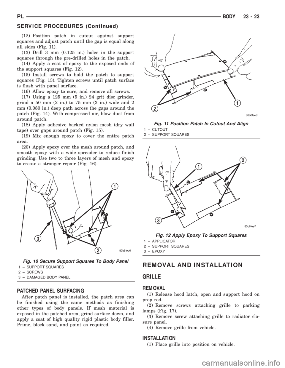
(12) Position patch in cutout against support
squares and adjust patch until the gap is equal along
all sides (Fig. 11).
(13) Drill 3 mm (0.125 in.) holes in the support
squares through the pre-drilled holes in the patch.
(14) Apply a coat of epoxy to the exposed ends of
the support squares (Fig. 12).
(15) Install screws to hold the patch to support
squares (Fig. 13). Tighten screws until patch surface
is flush with panel surface.
(16) Allow epoxy to cure, and remove all screws.
(17) Using a 125 mm (5 in.) 24 grit disc grinder,
grind a 50 mm (2 in.) to 75 mm (3 in.) wide and 2
mm (0.080 in.) deep path across the gaps around the
patch (Fig. 14). With compressed air, blow dust from
around patch.
(18) Apply adhesive backed nylon mesh (dry wall
tape) over gaps around patch (Fig. 15).
(19) Mix enough epoxy to cover the entire patch
area.
(20) Apply epoxy over the mesh around patch, and
smooth epoxy with a wide spreader to reduce finish
grinding. Use two to three layers of mesh and epoxy
to create a stronger repair (Fig. 16).
PATCHED PANEL SURFACING
After patch panel is installed, the patch area can
be finished using the same methods as finishing
other types of body panels. If mesh material is
exposed in the patched area, grind surface down, and
apply a coat of high quality rigid plastic body filler.
Prime, block sand, and paint as required.
REMOVAL AND INSTALLATION
GRILLE
REMOVAL
(1) Release hood latch, open and support hood on
prop rod.
(2) Remove screws attaching grille to parking
lamps (Fig. 17).
(3) Remove screw attaching grille to radiator clo-
sure panel.
(4) Remove grille from vehicle.
INSTALLATION
(1) Place grille into position on vehicle.
Fig. 10 Secure Support Squares To Body Panel
1 ± SUPPORT SQUARES
2 ± SCREWS
3 ± DAMAGED BODY PANEL
Fig. 11 Position Patch In Cutout And Align
1 ± CUTOUT
2 ± SUPPORT SQUARES
Fig. 12 Apply Epoxy To Support Squares
1 ± APPLICATOR
2 ± SUPPORT SQUARES
3 ± EPOXY
PLBODY 23 - 23
SERVICE PROCEDURES (Continued)
Page 1233 of 1285

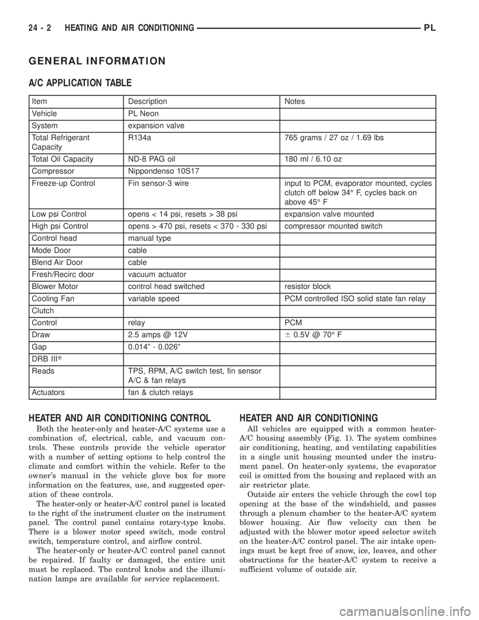
GENERAL INFORMATION
A/C APPLICATION TABLE
Item Description Notes
Vehicle PL Neon
System expansion valve
Total Refrigerant
CapacityR134a 765 grams / 27 oz / 1.69 lbs
Total Oil Capacity ND-8 PAG oil 180 ml / 6.10 oz
Compressor Nippondenso 10S17
Freeze-up Control Fin sensor-3 wire input to PCM, evaporator mounted, cycles
clutch off below 34É F, cycles back on
above 45É F
Low psi Control opens < 14 psi, resets > 38 psi expansion valve mounted
High psi Control opens > 470 psi, resets < 370 - 330 psi compressor mounted switch
Control head manual type
Mode Door cable
Blend Air Door cable
Fresh/Recirc door vacuum actuator
Blower Motor control head switched resistor block
Cooling Fan variable speed PCM controlled ISO solid state fan relay
Clutch
Control relay PCM
Draw 2.5 amps @ 12V60.5V @ 70É F
Gap 0.014º - 0.0269
DRB IIIT
Reads TPS, RPM, A/C switch test, fin sensor
A/C & fan relays
Actuators fan & clutch relays
HEATER AND AIR CONDITIONING CONTROL
Both the heater-only and heater-A/C systems use a
combination of, electrical, cable, and vacuum con-
trols. These controls provide the vehicle operator
with a number of setting options to help control the
climate and comfort within the vehicle. Refer to the
owner's manual in the vehicle glove box for more
information on the features, use, and suggested oper-
ation of these controls.
The heater-only or heater-A/C control panel is located
to the right of the instrument cluster on the instrument
panel. The control panel contains rotary-type knobs.
There is a blower motor speed switch, mode control
switch, temperature control, and airflow control.
The heater-only or heater-A/C control panel cannot
be repaired. If faulty or damaged, the entire unit
must be replaced. The control knobs and the illumi-
nation lamps are available for service replacement.
HEATER AND AIR CONDITIONING
All vehicles are equipped with a common heater-
A/C housing assembly (Fig. 1). The system combines
air conditioning, heating, and ventilating capabilities
in a single unit housing mounted under the instru-
ment panel. On heater-only systems, the evaporator
coil is omitted from the housing and replaced with an
air restrictor plate.
Outside air enters the vehicle through the cowl top
opening at the base of the windshield, and passes
through a plenum chamber to the heater-A/C system
blower housing. Air flow velocity can then be
adjusted with the blower motor speed selector switch
on the heater-A/C control panel. The air intake open-
ings must be kept free of snow, ice, leaves, and other
obstructions for the heater-A/C system to receive a
sufficient volume of outside air.
24 - 2 HEATING AND AIR CONDITIONINGPL