2000 DODGE NEON seats
[x] Cancel search: seatsPage 784 of 1285
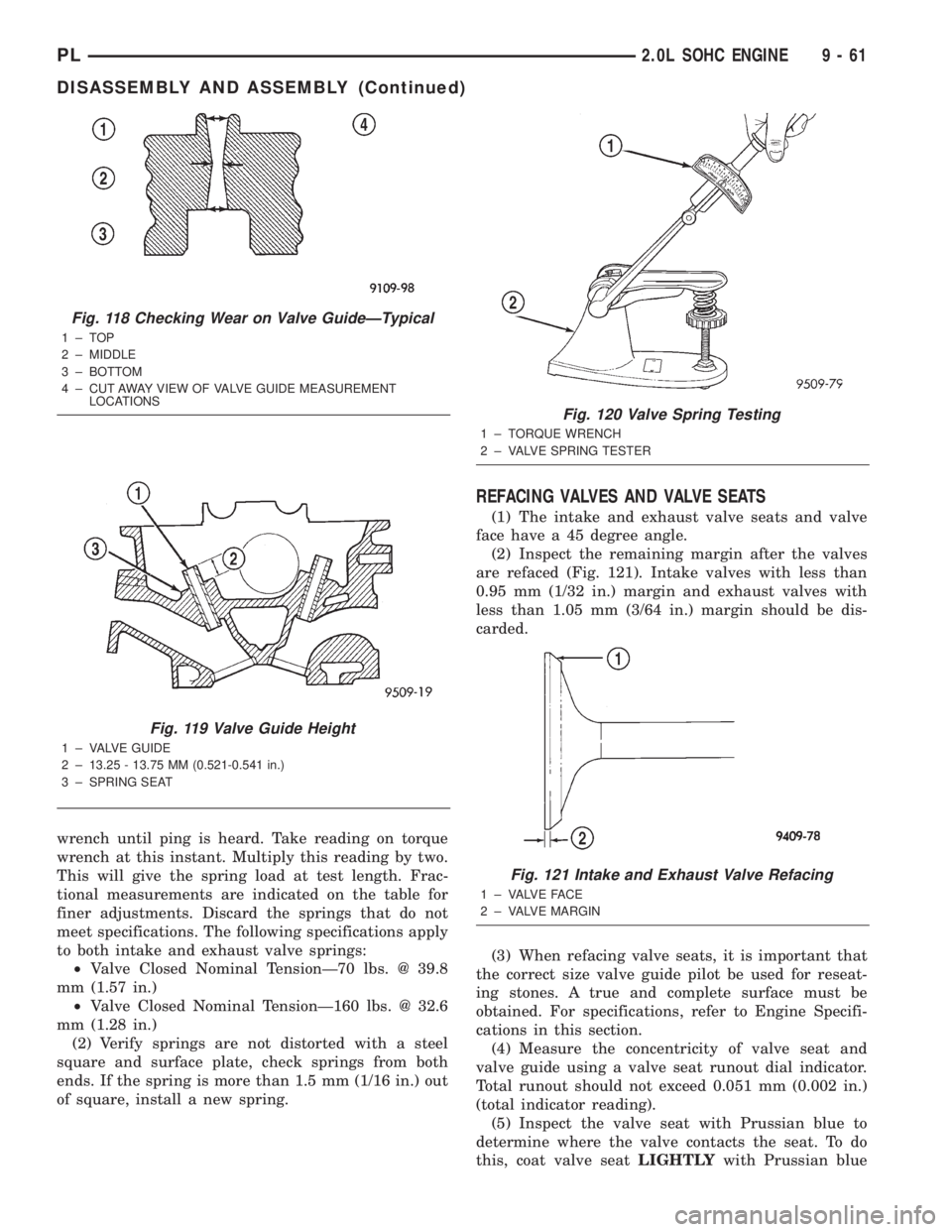
wrench until ping is heard. Take reading on torque
wrench at this instant. Multiply this reading by two.
This will give the spring load at test length. Frac-
tional measurements are indicated on the table for
finer adjustments. Discard the springs that do not
meet specifications. The following specifications apply
to both intake and exhaust valve springs:
²Valve Closed Nominal TensionÐ70 lbs. @ 39.8
mm (1.57 in.)
²Valve Closed Nominal TensionÐ160 lbs. @ 32.6
mm (1.28 in.)
(2) Verify springs are not distorted with a steel
square and surface plate, check springs from both
ends. If the spring is more than 1.5 mm (1/16 in.) out
of square, install a new spring.
REFACING VALVES AND VALVE SEATS
(1) The intake and exhaust valve seats and valve
face have a 45 degree angle.
(2) Inspect the remaining margin after the valves
are refaced (Fig. 121). Intake valves with less than
0.95 mm (1/32 in.) margin and exhaust valves with
less than 1.05 mm (3/64 in.) margin should be dis-
carded.
(3) When refacing valve seats, it is important that
the correct size valve guide pilot be used for reseat-
ing stones. A true and complete surface must be
obtained. For specifications, refer to Engine Specifi-
cations in this section.
(4) Measure the concentricity of valve seat and
valve guide using a valve seat runout dial indicator.
Total runout should not exceed 0.051 mm (0.002 in.)
(total indicator reading).
(5) Inspect the valve seat with Prussian blue to
determine where the valve contacts the seat. To do
this, coat valve seatLIGHTLYwith Prussian blue
Fig. 118 Checking Wear on Valve GuideÐTypical
1±TOP
2 ± MIDDLE
3 ± BOTTOM
4 ± CUT AWAY VIEW OF VALVE GUIDE MEASUREMENT
LOCATIONS
Fig. 119 Valve Guide Height
1 ± VALVE GUIDE
2 ± 13.25 - 13.75 MM (0.521-0.541 in.)
3 ± SPRING SEAT
Fig. 120 Valve Spring Testing
1 ± TORQUE WRENCH
2 ± VALVE SPRING TESTER
Fig. 121 Intake and Exhaust Valve Refacing
1 ± VALVE FACE
2 ± VALVE MARGIN
PL2.0L SOHC ENGINE 9 - 61
DISASSEMBLY AND ASSEMBLY (Continued)
Page 785 of 1285
then set valve in place. Rotate the valve with light
pressure. If the blue is transferred to the center of
valve face, contact is satisfactory. If the blue is trans-
ferred to top edge of the valve face, lower valve seat
with a 15 degrees stone. If the blue is transferred to
the bottom edge of valve face raise valve seat with a
65 degrees stone.
(6) Valve seats which are worn or burned can be
reworked, provided that correct angle and seat width
are maintained. The intake valve seat must be ser-
viced when the valve seat width is 2.0 mm (0.079 in.)
or greater. The exhaust valve seat must be serviced
when the valve seat width is 2.5 mm (0.098 in.) or
greater. Otherwise the cylinder head must be
replaced.
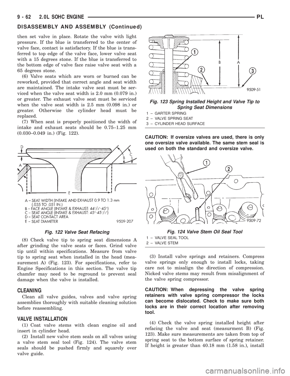
(7) When seat is properly positioned the width of
intake and exhaust seats should be 0.75±1.25 mm
(0.030±0.049 in.) (Fig. 122).
(8) Check valve tip to spring seat dimensions A
after grinding the valve seats or faces. Grind valve
tip until within specifications. Measure from valve
tip to spring seat when installed in the head (mea-
surement A) (Fig. 123). For specifications, refer to
Engine Specifications in this section. The valve tip
chamfer may need to be reground to prevent seal
damage when the valve is installed.
CLEANING
Clean all valve guides, valves and valve spring
assemblies thoroughly with suitable cleaning solution
before reassembling.
VALVE INSTALLATION
(1) Coat valve stems with clean engine oil and
insert in cylinder head.
(2) Install new valve stem seals on all valves using
a valve stem seal tool (Fig. 124). The valve stem
seals should be pushed firmly and squarely over
valve guide.CAUTION: If oversize valves are used, there is only
one oversize valve available. The same stem seal is
used on both the standard and oversize valve.
(3) Install valve springs and retainers. Compress
valve springs only enough to install locks, taking
care not to misalign the direction of compression.
Nicked valve stems may result from misalignment of
the valve spring compressor.
CAUTION: When depressing the valve spring
retainers with valve spring compressor the locks
can become dislocated. Check to make sure both
locks are in their correct location after removing
tool.
(4) Check the valve spring installed height after
refacing the valve and seat (measurment B) (Fig.
123). Make sure measurements are taken from top of
spring seat to the bottom surface of spring retainer.
If height is greater than 40.18 mm (1.58 in.), install
Fig. 122 Valve Seat Refacing
Fig. 123 Spring Installed Height and Valve Tip to
Spring Seat Dimensions
1 ± GARTER SPRING
2 ± VALVE SPRING SEAT
3 ± CYLINDER HEAD SURFACE
Fig. 124 Valve Stem Oil Seal Tool
1 ± VALVE SEAL TOOL
2 ± VALVE STEM
9 - 62 2.0L SOHC ENGINEPL
DISASSEMBLY AND ASSEMBLY (Continued)
Page 831 of 1285
(3) Squeeze retainer tabs together and pull fuel
tube/quick-connect fitting assembly off of fuel tube
nipple. The retainer will remain on fuel tube.
INSTALLATION
CAUTION: Never install a quick-connect fitting
without the retainer being either on the fuel tube or
already in the quick-connect fitting. In either case,
ensure the retainer locks securely into the quick-
connect fitting by firmly pulling on fuel tube and fit-
ting to ensure it is secured.
(1) Using a clean lint free cloth, clean the fuel tube
nipple and retainer.
(2) Prior to connecting the fitting to the fuel tube,
coat the fuel tube nipple with clean 30 weight engine
oil.
(3) Push the quick-connect fitting over the fuel
tube until theretainer seats and a click is heard.
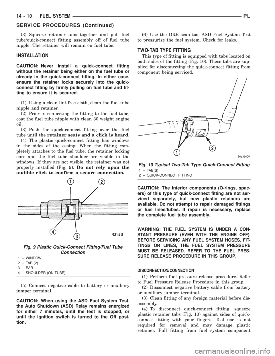
(4) The plastic quick-connect fitting has windows
in the sides of the casing. When the fitting com-
pletely attaches to the fuel tube, the retainer locking
ears and the fuel tube shoulder are visible in the
windows. If they are not visible, the retainer was not
properly installed (Fig. 9).Do not rely upon the
audible click to confirm a secure connection.
(5) Connect negative cable to battery or auxiliary
jumper terminal.
CAUTION: When using the ASD Fuel System Test,
the Auto Shutdown (ASD) Relay remains energized
for either 7 minutes, until the test is stopped, or
until the ignition switch is turned to the Off posi-
tion.(6) Use the DRB scan tool ASD Fuel System Test
to pressurize the fuel system. Check for leaks.
TWO-TAB TYPE FITTING
This type of fitting is equipped with tabs located on
both sides of the fitting (Fig. 10). These tabs are sup-
plied for disconnecting the quick-connect fitting from
component being serviced.
CAUTION: The interior components (O-rings, spac-
ers) of this type of quick-connect fitting are not ser-
viced separately, but new plastic retainers are
available. Do not attempt to repair damaged fittings
or fuel lines/tubes. If repair is necessary, replace
the complete fuel tube assembly.
WARNING:
THE FUEL SYSTEM IS UNDER A CON-
STANT PRESSURE (EVEN WITH THE ENGINE OFF).
BEFORE SERVICING ANY FUEL SYSTEM HOSES, FIT-
TINGS OR LINES, THE FUEL SYSTEM PRESSURE
MUST BE RELEASED. REFER TO THE FUEL PRES-
SURE RELEASE PROCEDURE IN THIS GROUP.
DISCONNECTION/CONNECTION
(1) Perform fuel pressure release procedure. Refer
to Fuel Pressure Release Procedure in this group.
(2) Disconnect negative battery cable from battery
or auxiliary jumper terminal.
(3) Clean fitting of any foreign material before dis-
assembly.
(4) To disconnect quick-connect fitting, squeeze
plastic retainer tabs (Fig. 10) against sides of quick-
connect fitting with your fingers. Tool use is not
required for removal and may damage plastic
retainer. Pull fitting from fuel system component
Fig. 9 Plastic Quick-Connect Fitting/Fuel Tube
Connection
1 ± WINDOW
2 ± TAB (2)
3 ± EAR
4 ± SHOULDER (ON TUBE)
Fig. 10 Typical Two-Tab Type Quick-Connect Fitting
1 ± TAB(S)
2 ± QUICK-CONNECT FITTING
14 - 10 FUEL SYSTEMPL
SERVICE PROCEDURES (Continued)
Page 1082 of 1285
METHOD 2 (RELOCATE TIRE ON WHEEL)
Rotating tire on wheel is particularly effective
when there is run out in both tire and wheel.
Remove tire from wheel and remount wheel on hub
in former position.
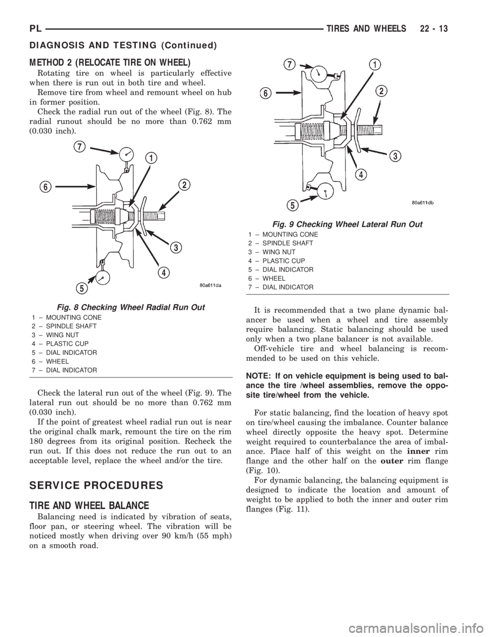
Check the radial run out of the wheel (Fig. 8). The
radial runout should be no more than 0.762 mm
(0.030 inch).
Check the lateral run out of the wheel (Fig. 9). The
lateral run out should be no more than 0.762 mm
(0.030 inch).
If the point of greatest wheel radial run out is near
the original chalk mark, remount the tire on the rim
180 degrees from its original position. Recheck the
run out. If this does not reduce the run out to an
acceptable level, replace the wheel and/or the tire.
SERVICE PROCEDURES
TIRE AND WHEEL BALANCE
Balancing need is indicated by vibration of seats,
floor pan, or steering wheel. The vibration will be
noticed mostly when driving over 90 km/h (55 mph)
on a smooth road.It is recommended that a two plane dynamic bal-
ancer be used when a wheel and tire assembly
require balancing. Static balancing should be used
only when a two plane balancer is not available.
Off-vehicle tire and wheel balancing is recom-
mended to be used on this vehicle.
NOTE: If on vehicle equipment is being used to bal-
ance the tire /wheel assemblies, remove the oppo-
site tire/wheel from the vehicle.
For static balancing, find the location of heavy spot
on tire/wheel causing the imbalance. Counter balance
wheel directly opposite the heavy spot. Determine
weight required to counterbalance the area of imbal-
ance. Place half of this weight on theinnerrim
flange and the other half on theouterrim flange
(Fig. 10).
For dynamic balancing, the balancing equipment is
designed to indicate the location and amount of
weight to be applied to both the inner and outer rim
flanges (Fig. 11).
Fig. 8 Checking Wheel Radial Run Out
1 ± MOUNTING CONE
2 ± SPINDLE SHAFT
3 ± WING NUT
4 ± PLASTIC CUP
5 ± DIAL INDICATOR
6 ± WHEEL
7 ± DIAL INDICATOR
Fig. 9 Checking Wheel Lateral Run Out
1 ± MOUNTING CONE
2 ± SPINDLE SHAFT
3 ± WING NUT
4 ± PLASTIC CUP
5 ± DIAL INDICATOR
6 ± WHEEL
7 ± DIAL INDICATOR
PLTIRES AND WHEELS 22 - 13
DIAGNOSIS AND TESTING (Continued)
Page 1118 of 1285
BODY
TABLE OF CONTENTS
page page
PAINT................................... 1
STATIONARY GLASS........................ 4
SEATS ................................... 8BODY COMPONENTS...................... 12
SPECIFICATIONS......................... 60
PAINT
TABLE OF CONTENTS
page page
DESCRIPTION AND OPERATION
PAINT CODE.............................1
BASE COAT/CLEAR COAT FINISH.............1
WET SANDING, BUFFING, AND POLISHING.....1PAINTED SURFACE TOUCH-UP..............1
SPECIFICATIONS
AFTERMARKET PAINT REPAIR PRODUCTS.....2
DESCRIPTION AND OPERATION
PAINT CODE
A paint code is provided on the body code plate
located in the engine compartment. Refer to the
Introduction section at the front of this manual for
body code plate description. The paint and trim codes
are also included on the Vehicle Safety Label located
on the driver's door end frame.
BASE COAT/CLEAR COAT FINISH
On most vehicles a two-part paint application (base
coat/clear coat) is used. Color paint that is applied to
primer is called base coat. The clear coat protects the
base coat from ultraviolet light and provides a dura-
ble high-gloss finish.
CAUTION: Do not use abrasive chemicals or com-
pounds on painted surfaces. Damage to finish can
result.
Do not use harsh alkaline based cleaning sol-
vents on painted surfaces. Damage to finish or
color can result.
WET SANDING, BUFFING, AND POLISHING
Minor acid etching, orange peel, or smudging in
clear coat or single-stage finishes can be reduced
with light wet sanding, hand buffing, and polishing.
If the finish has been wet sanded in the past, itcannot be repeated. Wet sanding operation
should be performed by a trained automotive
paint technician.
CAUTION: Do not remove clear coat finish, if
equipped. Base coat paint must retain clear coat for
durability.
PAINTED SURFACE TOUCH-UP
When a painted metal surface has been scratched
or chipped, it should be touched-up as soon as possi-
ble to avoid corrosion. For best results, use Mopart
Scratch Filler/Primer, Touch-Up Paints and Clear Top
Coat. Refer to Introduction group of this manual for
Body Code Plate information.
CAUTION: USE A OSHA APPROVED BREATHING
FILTER WHEN SPRAYING PAINT OR SOLVENTS IN
A CONFINED AREA. PERSONAL INJURY CAN
RESULT.
TOUCH-UP PROCEDURE
(1) Scrape loose paint and corrosion from inside
scratch or chip.
(2) Clean affected area with MopartTar/Road Oil
Remover, and allow to dry.
(3) Fill the inside of the scratch or chip with a coat
of filler/primer. Do not overlap primer onto good sur-
PLBODY 23 - 1
Page 1125 of 1285
SEATS
TABLE OF CONTENTS
page page
REMOVAL AND INSTALLATION
FRONT SEAT.............................8
FRONT SEAT BACK........................8
FRONT SEAT BACK COVER.................9FRONT SEAT CUSHION COVER..............9
FRONT SEAT CUSHION....................9
REAR SEAT BACK........................10
REAR SEAT CUSHION.....................11
REMOVAL AND INSTALLATION
FRONT SEAT
REMOVAL
(1) Move seat to forward position.
(2) Remove bolts attaching rear of seat track to
floor.
(3) Move seat to rearward position.
(4) Remove bolts attaching front of seat track to
floor crossmember (Fig. 1).
(5) Remove seat from vehicle.
INSTALLATION
(1) Move seat to mid-position andverifythat both
seat tracks are locked into same position with eight
teeth behind the latch mechanism.
(2) Move seat into position in vehicle. Do not use
the head restraint, side shield, recliner handle, or the
adjuster lift bar to move the seat.(3) Ensure that the locating tabs on the front
mounting feet are installed through the slits in the
carpet and into the openings in the floor pan cross-
member.
(4) Install and tighten front inboard bolt attaching
seat track to floor crossmember.
(5) Install front outboard bolt attaching seat track
to floor crossmember. Tighten front seat bolt to 55
N´m (40 ft. lbs.) torque.
(6) Install rear seat track attaching bolts to floor.
Tighten rear seat bolts outboard first then inboard to
55 N´m (40 ft. lbs.) torque.
FRONT SEAT BACK
REMOVAL
(1) Remove seat from vehicle.
(2) Remove seat cushion side shields.
(3) Remove bolts attaching recliner to seat back
cushion frame (Fig. 2).
(4) Remove inboard pivot bolt (Fig. 3).
(5) Disconnect any electrical connectors to the seat
back, if equipped.
(6) Remove seat back from seat cushion.
Fig. 1 Front Seat
1 ± SEAT
2 ± SEAT BELT BOLT
Fig. 2 Recliner Attaching Bolt
1 ± RECLINER BOLT
23 - 8 BODYPL
Page 1173 of 1285
(3) Remove rear seat closure panel silencer pad as
necessary to gain access to retractor.
(4) Remove bolt attaching seat belt lower anchor to
floor.
(5) Remove bolt attaching retractor to rear seat
closure panel (Fig. 71).
(6) Push seat belt bezel and buckle stab through
access hole in parcel shelf.
(7) From in trunk compartment, remove rear seat
belt retractor from vehicle.
INSTALLATION
(1) Position rear seat belt retractor in trunk com-
partment.
(2) Push seat belt bezel and buckle stab through
access hole in rear shelf trim panel.
(3) Install bolt attaching retractor to rear seat clo-
sure panel. Tighten the seat belt bolt to 40 N´m (30
ft. lbs.) torque.
(4) Install bolt attaching seat belt lower anchor to
floor. Tighten the seat belt bolt to 40 N´m (30 ft. lbs.)
torque.
(5) Install rear seat closure panel silencer pad.
(6) Install seat belt bezel to the rear shelf trim
panel.
(7) Install rear seat cushion and back.
CARPET
REMOVAL
For removal of the carpet, the carpet will need to
be cut under the instrument panel.
(1) Remove front seats.
(2) Remove rear seat cushion.
(3) Remove bolts attaching front seat belt lower
anchors to floor (Fig. 72).(4) Remove door sill trim covers.
(5) Remove cowl trim covers.
(6) Remove center floor console.
(7) Remove decklid release assist handle.
(8) Remove lower fasteners from B-pillar trim
panel.
(9) Pull carpet from behind trim panel.
(10) Fold carpet in half toward rear seat.
(11) Remove carpet through rear door opening.
INSTALLATION
The new carpet must be cut for installation. The
area is mark on the reverse side of the carpet. The
location is in front of the tunnel area.
(1) Install carpet through rear door opening.
(2) Unfold carpet.
(3) Tuck carpet behind trim panel.
(4) Install lower fasteners holding B-pillar trim
panel.
(5) Install decklid release assist handle.
(6) Install center floor console.
(7) Install cowl trim covers.
(8) Install door sill trim covers.
(9) Install bolts attaching front seat belt lower
anchors to floor. Tighten all seat belts to 40 N´m (30
ft. lbs.) torque.
(10) Install rear seat cushion.
(11) Install front seats.
SUN VISOR
All vehicles with driver and passenger side airbags
must have a colored coded five Bullet point airbag
Fig. 71 Rear Seat Belt Retractor
1 ± REAR RIGHT OUTER SEAT BELT
2 ± SEAT BELT RETRACTOR
Fig. 72 Carpet
1 ± FLOOR CARPET
2 ± TRUNK REAR END PANEL
23 - 56 BODYPL
REMOVAL AND INSTALLATION (Continued)