2000 DODGE NEON recommended oil
[x] Cancel search: recommended oilPage 308 of 1285
LAMPS
TABLE OF CONTENTS
page page
LAMP DIAGNOSIS......................... 1
HEADLAMP ALIGNMENT.................... 4
LAMP BULB SERVICE...................... 7LAMP SERVICE........................... 12
LAMP SYSTEMS.......................... 16
BULB APPLICATION....................... 17
LAMP DIAGNOSIS
TABLE OF CONTENTS
page page
DESCRIPTION AND OPERATION
DIAGNOSTIC PROCEDURES................1
SAFETY PRECAUTIONS....................1
DAYTIME RUNNING LAMP MODULE...........1DIAGNOSIS AND TESTING
HEADLAMP DIAGNOSIS....................1
FOG LAMP..............................3
DESCRIPTION AND OPERATION
DIAGNOSTIC PROCEDURES
When a vehicle experiences problems with the
headlamp system, verify the condition of the battery
connections, fuses, charging system, headlamp bulbs,
wire connectors, relay, high beam switch, dimmer
switch, and headlamp switch. Refer to Group 8W,
Wiring Diagrams for component locations and circuit
information.
SAFETY PRECAUTIONS
WARNING: EYE PROTECTION SHOULD BE USED
WHEN SERVICING GLASS COMPONENTS. PER-
SONAL INJURY CAN RESULT.
CAUTION: Do not touch the glass of halogen bulbs
with fingers or other possibly oily surface, reduced
bulb life will result.
Do not use bulbs with higher candle power than
indicated in the Bulb Application table at the end of
this group. Damage to lamp and/or Daytime Run-
ning Lamp Module can result.
Do not use fuses, circuit breakers or relays hav-
ing greater amperage value than indicated on the
fuse panel or in the Owners Manual.When it is necessary to remove components to ser-
vice another, it should not be necessary to apply
excessive force or bend a component to remove it.
Before damaging a trim component, verify hidden
fasteners or captured edges are not holding the com-
ponent in place.
DAYTIME RUNNING LAMP MODULE
PL vehicles built for use in Canada are equipped
with a Daytime Running Lamp (DRL) system. Turn
signal lamp circuitry always comes from the multi-
function switch, and goes to the cluster connector,
into the cluster, then back out to the front turn sig-
nal switch lamps. The Canadian cluster provides
steady illumination of the front turn signal when the
ignition switch is in the ON position. The DRL func-
tion may be inhibited by activating the turn signals,
the hazard flashers, the headlamp switch, or park
brake.
DIAGNOSIS AND TESTING
HEADLAMP DIAGNOSIS
Always begin any diagnosis by testing all of the
fuses and circuit breakers in the system. Refer to
Group 8W, Wiring Diagrams.
Conventional and halogen headlamps are inter-
changeable. It is recommended that they not be
intermixed on a given vehicle.
PLLAMPS 8L - 1
Page 725 of 1285
MOPARtGASKET SEALANT
MopartGasket Sealant is a slow drying, perma-
nently soft sealer. This material is recommended for
sealing threaded fittings and gaskets against leakage
of oil and coolant. Can be used on threaded and
machined parts under all temperatures. This mate-
rial is used on engines with multi-layer steel (MLS)
cylinder head gaskets. This material also will pre-
vent corrosion. MopartGasket Sealant is available in
a 13 oz. aerosol can or 4 oz./16 oz. can w/applicator.
FORM-IN-PLACE GASKET AND SEALER
APPLICATION
Assembling parts using a form-in-place gasket
requires care but it's easier then using precut gas-
kets.
MopartGasket Maker material should be applied
sparingly 1 mm (0.040 in.) diameter or less of sealant
to one gasket surface. Be certain the material sur-
rounds each mounting hole. Excess material can eas-
ily be wiped off. Components should be torqued in
place within 15 minutes. The use of a locating dowel
is recommended during assembly to prevent smear-
ing material off the location.
MopartEngine RTV GEN II or ATF RTV gasket
material should be applied in a continuous bead
approximately 3 mm (0.120 in.) in diameter. All
mounting holes must be circled. For corner sealing, a
3.17 or 6.35 mm (1/8 or 1/4 in.) drop is placed in the
center of the gasket contact area. Uncured sealant
may be removed with a shop towel. Components
should be torqued in place while the sealant is still
wet to the touch (within 10 minutes). The usage of a
locating dowel is recommended during assembly to
prevent smearing material off the location.
MopartGasket Sealant in an aerosol can should be
applied using a thin, even coat sprayed completely
over both surfaces to be joined, and both sides of a
gasket. Then proceed with assembly. Material in a
can w/applicator can be brushed on evenly over the
sealing surfaces. Material in an aerosol can should be
used on engines with multi-layer steel gaskets.
ENGINE GASKET SURFACE PREPARATION
To ensure engine gasket sealing, proper surface
preparation must be performed, especially with the
use of aluminum engine components and multi-layer
steel cylinder head gaskets.
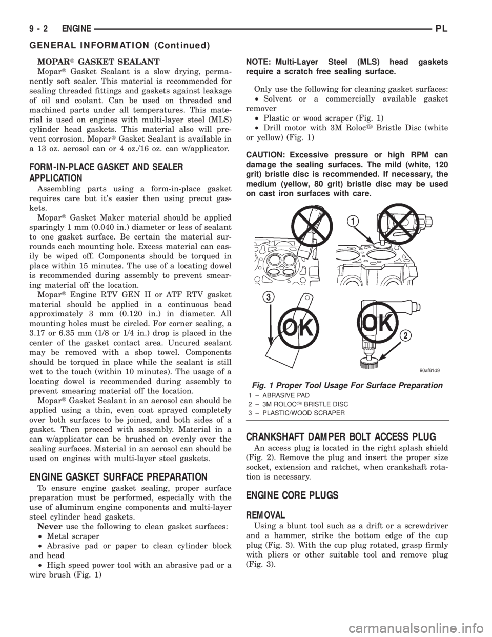
Neveruse the following to clean gasket surfaces:
²Metal scraper
²Abrasive pad or paper to clean cylinder block
and head
²High speed power tool with an abrasive pad or a
wire brush (Fig. 1)NOTE: Multi-Layer Steel (MLS) head gaskets
require a scratch free sealing surface.
Only use the following for cleaning gasket surfaces:
²Solvent or a commercially available gasket
remover
²Plastic or wood scraper (Fig. 1)
²Drill motor with 3M RolocyBristle Disc (white
or yellow) (Fig. 1)
CAUTION: Excessive pressure or high RPM can
damage the sealing surfaces. The mild (white, 120
grit) bristle disc is recommended. If necessary, the
medium (yellow, 80 grit) bristle disc may be used
on cast iron surfaces with care.
CRANKSHAFT DAMPER BOLT ACCESS PLUG
An access plug is located in the right splash shield
(Fig. 2). Remove the plug and insert the proper size
socket, extension and ratchet, when crankshaft rota-
tion is necessary.
ENGINE CORE PLUGS
REMOVAL
Using a blunt tool such as a drift or a screwdriver
and a hammer, strike the bottom edge of the cup
plug (Fig. 3). With the cup plug rotated, grasp firmly
with pliers or other suitable tool and remove plug
(Fig. 3).
Fig. 1 Proper Tool Usage For Surface Preparation
1 ± ABRASIVE PAD
2 ± 3M ROLOCYBRISTLE DISC
3 ± PLASTIC/WOOD SCRAPER
9 - 2 ENGINEPL
GENERAL INFORMATION (Continued)
Page 726 of 1285

CAUTION: Do not drive cup plug into the casting
as restricted cooling can result and cause serious
engine problems.
INSTALLATION
Thoroughly clean all debris/rust from inside of cup
plug hole in cylinder block or head. Be sure to
remove old sealer. Lightly coat inside of cup plug hole
with MopartStud and Bearing Mount Adhesive.
Make certain the new plug is cleaned of all oil or
grease. Using a proper driver, drive plug into hole so
that the sharp edge of the plug is at least 0.5 mm
(0.020 inch.) inside the lead in chamfer (Fig. 3).
It is not necessary to wait for curing of the sealant.
The cooling system can be refilled and the vehicle
placed in service immediately.
ENGINE PERFORMANCE
If a loss of performance is noticed, timing belt or
chain may have skipped one or two teeth. Camshaft
and crankshaft timing should be checked. Refer to
Group 9, Engine Timing belt or chain installation.
It is important that the vehicle is operating to it's
optimum performance level to maintain fuel economy
and lowest vehicle emissions. If vehicle is not operat-ing to these standards, refer to Engine Diagnosis in
this section. The following procedures can assist in
achieving the proper engine diagnosis.
(1) Test cranking amperage draw. Refer to Group
8B, Starting.
(2) Check intake manifold for vacuum leaks.
(3) Perform cylinder compression pressure test.
Refer to Engine Diagnosis in this section.
(4) Clean or replace spark plugs as necessary and
adjust gap as specified in Group 8D, Ignition System.
Tighten to specifications.
(5) Test resistance of spark plug cables. Refer to
Group 8D, Ignition System.
(6) Test ignition coils primary and secondary resis-
tance. Replace parts as necessary. Refer to Group 8D,
Ignition System.
(7) Check fuel pump pressure at idle and different
RPM ranges. Refer to Group 14, Fuel System for
specifications.
(8) The air filter elements should be replaced as
specified in Group 0, Lubrication and Maintenance.
(9) Inspect crankcase ventilation system. Refer to
Group 25, Emission Control Systems.
(10) Road test vehicle as a final test.HONING CYLINDER BORES
(1) Used carefully, the cylinder bore resizing hone,
recommended tool C-823 or equivalent, equipped
with 220 grit stones, is the best tool for this honing
procedure. In addition to deglazing, it will reduce
taper and out-of-round as well as removing light
scuffing, scoring or scratches. Usually a few strokes
Fig. 2 Access Plug
1 ± CRANKSHAFT BOLT ACCESS PLUG
2 ± RIGHT MOUNT BOLT ACCESS PLUG
3 ± FASCIA
4 ± SPLASH SHIELD
Fig. 3 Core Hole Plug Removal
1 ± CYLINDER BLOCK
2 ± REMOVE PLUG WITH PLIERS
3 ± STRIKE HERE WITH HAMMER
4 ± DRIFT PUNCH
5 ± CUP PLUG
PLENGINE 9 - 3
GENERAL INFORMATION (Continued)
Page 727 of 1285
will clean up a bore and maintain the required lim-
its.
(2) Deglazing of the cylinder walls may be done
using a cylinder surfacing hone, recommended tool
C-3501 or equivalent, equipped with 280 grit stones,
if the cylinder bore is straight and round. 20±60
strokes depending on the bore condition, will be suf-
ficient to provide a satisfactory surface. Inspect cyl-
inder walls after each 20 strokes, using a light
honing oil.Do not use engine or transmission oil,
mineral spirits or kerosene.
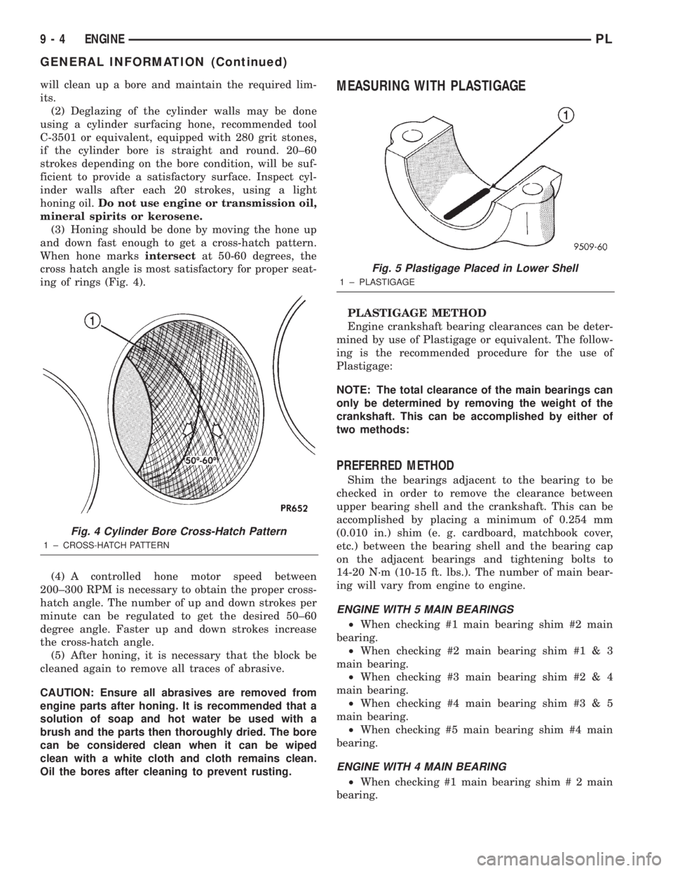
(3) Honing should be done by moving the hone up
and down fast enough to get a cross-hatch pattern.
When hone marksintersectat 50-60 degrees, the
cross hatch angle is most satisfactory for proper seat-
ing of rings (Fig. 4).
(4) A controlled hone motor speed between
200±300 RPM is necessary to obtain the proper cross-
hatch angle. The number of up and down strokes per
minute can be regulated to get the desired 50±60
degree angle. Faster up and down strokes increase
the cross-hatch angle.
(5) After honing, it is necessary that the block be
cleaned again to remove all traces of abrasive.
CAUTION: Ensure all abrasives are removed from
engine parts after honing. It is recommended that a
solution of soap and hot water be used with a
brush and the parts then thoroughly dried. The bore
can be considered clean when it can be wiped
clean with a white cloth and cloth remains clean.
Oil the bores after cleaning to prevent rusting.MEASURING WITH PLASTIGAGE
PLASTIGAGE METHOD
Engine crankshaft bearing clearances can be deter-
mined by use of Plastigage or equivalent. The follow-
ing is the recommended procedure for the use of
Plastigage:
NOTE: The total clearance of the main bearings can
only be determined by removing the weight of the
crankshaft. This can be accomplished by either of
two methods:
PREFERRED METHOD
Shim the bearings adjacent to the bearing to be
checked in order to remove the clearance between
upper bearing shell and the crankshaft. This can be
accomplished by placing a minimum of 0.254 mm
(0.010 in.) shim (e. g. cardboard, matchbook cover,
etc.) between the bearing shell and the bearing cap
on the adjacent bearings and tightening bolts to
14-20 N´m (10-15 ft. lbs.). The number of main bear-
ing will vary from engine to engine.
ENGINE WITH 5 MAIN BEARINGS
²When checking #1 main bearing shim #2 main
bearing.
²When checking #2 main bearing shim #1 & 3
main bearing.
²When checking #3 main bearing shim #2 & 4
main bearing.
²When checking #4 main bearing shim #3 & 5
main bearing.
²When checking #5 main bearing shim #4 main
bearing.
ENGINE WITH 4 MAIN BEARING
²When checking #1 main bearing shim # 2 main
bearing.
Fig. 4 Cylinder Bore Cross-Hatch Pattern
1 ± CROSS-HATCH PATTERN
Fig. 5 Plastigage Placed in Lower Shell
1 ± PLASTIGAGE
9 - 4 ENGINEPL
GENERAL INFORMATION (Continued)
Page 728 of 1285

²When checking #2 main bearing shim #1 & #3
main bearing.
²When checking #3 main bearing shim #2 & #4
main bearing.
²When checking #4 main bearing shim #3 main
bearing.
NOTE: REMOVE ALL SHIMS BEFORE REASSEM-
BLING ENGINE
ALTERNATIVE METHOD
The weight of the crankshaft can be supported by a
jack under the counterweight adjacent to the bearing
being checked.
PLASTIGAGE PROCEDURE
(1) Remove oil film from surface to be checked.
Plastigage is soluble in oil.
(2) Place a piece of Plastigage across the entire
width of the bearing shell in the cap approximately
6.35 mm (1/4 in.) off center and away from the oil
holes (Fig. 5). (In addition, suspected areas can be
checked by placing the Plastigage in the suspected
area). Torque the bearing cap bolts of the bearing
being checked to the proper specifications.
(3) Remove the bearing cap and compare the width
of the flattened Plastigage (Fig. 6) with the metric
scale provided on the package. Locate the band clos-
est to the same width. This band shows the amount
of clearance in thousandths of a millimeter. Differ-
ences in readings between the ends indicate the
amount of taper present. Record all readings taken.
Refer to Engine Specifications.Plastigage gener-
ally is accompanied by two scales. One scale is
in inches, the other is a metric scale.
NOTE: Plastigage is available in a variety of clear-
ance ranges. Use the most appropriate range for
the specifications you are checking.
CONNECTING ROD BEARING CLEARANCE
Engine connecting rod bearing clearances can be
determined by use of Plastigage or equivalent. Thefollowing is the recommended procedure for the use
of Plastigage:
(1) Rotate the crankshaft until the connecting rod
to be checked is at the bottom of its stroke.
(2) Remove oil film from surface to be checked.
Plastigage is soluble in oil.
(3) Place a piece of Plastigage across the entire
width of the bearing shell in the bearing cap approx-
imately 6.35 mm (1/4 in.) off center and away from
the oil hole (Fig. 5). In addition, suspect areas can be
checked by placing plastigage in that area.
(4) Assemble the rod cap with Plastigage in place.
Tighten the rod cap to the specified torque.Do not
rotate the crankshaft while assembling the cap
or the Plastigage may be smeared, giving inac-
curate results.
(5) Remove the bearing cap and compare the width
of the flattened Plastigage (Fig. 6) with the scale pro-
vided on the package. Locate the band closest to the
same width. This band indicates the amount of oil
clearance. Differences in readings between the ends
indicate the amount of taper present. Record all
readings taken. Refer to Engine Specifications.Plas-
tigage generally is accompanied by two scales.
One scale is in inches, the other is a metric
scale. If the bearing clearance exceeds wear
limit specification, replace the bearing.
REPAIR OF DAMAGED OR WORN THREADS
Damaged or worn threads (including aluminum
head spark plug threads) can be repaired. Essen-
tially, this repair consists of drilling out worn or
damaged threads, tapping the hole with a special
Heli-Coil Tap, (or equivalent) and installing an insert
into the tapped hole. This brings the hole back to its
original thread size.
CAUTION: Be sure that the tapped holes maintain
the original centerline.
Heli-Coil tools and inserts are readily available
from automotive parts jobbers.
HYDROSTATIC LOCKED ENGINE
When an engine is suspected to be hydrostatically
locked, regardless of what caused the problem, the
following steps should be used.
CAUTION: DO NOT use starter motor to rotate the
engine, severe damage may occur.
(1) Inspect air cleaner, induction system and
intake manifold to insure system is dry and clear of
foreign material.
(2) Remove negative battery cable.
(3) Place a shop towel around the spark plugs
when removing them from the engine. This will catch
Fig. 6 Clearance Measurement
PLENGINE 9 - 5
GENERAL INFORMATION (Continued)
Page 730 of 1285
ENGINE OIL SERVICE
WARNING: NEW OR USED ENGINE OIL CAN BE
IRRITATING TO THE SKIN. AVOID PROLONGED OR
REPEATED SKIN CONTACT WITH ENGINE OIL.
CONTAMINANTS IN USED ENGINE OIL, CAUSED BY
INTERNAL COMBUSTION, CAN BE HAZARDOUS TO
YOUR HEALTH. THOROUGHLY WASH EXPOSED
SKIN WITH SOAP AND WATER. DO NOT WASH
SKIN WITH GASOLINE, DIESEL FUEL, THINNER, OR
SOLVENTS, HEALTH PROBLEMS CAN RESULT. DO
NOT POLLUTE, DISPOSE OF USED ENGINE OIL
PROPERLY. CONTACT YOUR DEALER OR GOVERN-
MENT AGENCY FOR LOCATION OF COLLECTION
CENTER IN YOUR AREA.
ENGINE OIL SPECIFICATION
CAUTION: Do not use non-detergent or straight
mineral oil when adding or changing crankcase
lubricant. Engine failure can result.
API SERVICE GRADE CERTIFIED
Use an engine oil that is API Service Grade Certi-
fied. MOPARtprovides engine oils that conforms to
this service grade.
SAE VISCOSITY
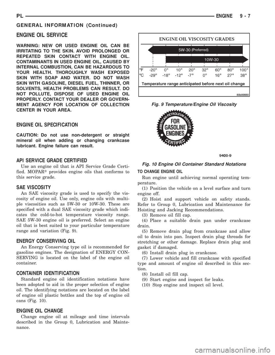
An SAE viscosity grade is used to specify the vis-
cosity of engine oil. Use only, engine oils with multi-
ple viscosities such as 5W-30 or 10W-30. These are
specified with a dual SAE viscosity grade which indi-
cates the cold-to-hot temperature viscosity range.
SAE 5W-30 engine oil is preferred. Select an engine
oil that is best suited to your particular temperature
range and variation (Fig. 9).
ENERGY CONSERVING OIL
An Energy Conserving type oil is recommended for
gasoline engines. The designation of ENERGY CON-
SERVING is located on the label of the engine oil
container.
CONTAINER IDENTIFICATION
Standard engine oil identification notations have
been adopted to aid in the proper selection of engine
oil. The identifying notations are located on the label
of engine oil plastic bottles and the top of engine oil
cans (Fig. 10).
ENGINE OIL CHANGE
Change engine oil at mileage and time intervals
described in the Group 0, Lubrication and Mainte-
nance.TO CHANGE ENGINE OIL
Run engine until achieving normal operating tem-
perature.
(1) Position the vehicle on a level surface and turn
engine off.
(2) Hoist and support vehicle on safety stands.
Refer to Group 0, Lubrication and Maintenance for
Hoisting and Jacking Recommendations.
(3) Remove oil fill cap.
(4) Place a suitable drain pan under crankcase
drain.
(5) Remove drain plug from crankcase and allow
oil to drain into pan. Inspect drain plug threads for
stretching or other damage. Replace drain plug and
gasket if damaged.
(6) Install drain plug in crankcase.
(7) Lower vehicle and fill crankcase with specified
type and amount of engine oil described in this sec-
tion.
(8) Install oil fill cap.
(9) Start engine and inspect for leaks.
(10) Stop engine and inspect oil level.
Fig. 9 Temperature/Engine Oil Viscosity
Fig. 10 Engine Oil Container Standard Notations
PLENGINE 9 - 7
GENERAL INFORMATION (Continued)
Page 731 of 1285
ENGINE DIAGNOSIS
TABLE OF CONTENTS
page page
DIAGNOSIS AND TESTING
GENERAL INFORMATION...................8
INTAKE MANIFOLD LEAKAGE DIAGNOSIS......8
CYLINDER COMPRESSION PRESSURE TEST . . . 8
CYLINDER COMBUSTION PRESSURE
LEAKAGE TEST.........................9LASH ADJUSTER (TAPPET) NOISE
DIAGNOSIS............................9
ENGINE OIL LEAK INSPECTION..............9
ENGINE DIAGNOSISÐPERFORMANCE........11
ENGINE DIAGNOSISÐMECHANICAL.........12
DIAGNOSIS AND TESTING
GENERAL INFORMATION
Engine diagnosis is helpful in determining the
causes of malfunctions not detected and remedied by
routine maintenance.
These malfunctions may be classified as either
mechanical (e.g., a strange noise), or performance
(e.g., engine idles rough and stalls).
Refer to the Service DiagnosisÐMechanical Chart
and the Service DiagnosisÐPerformance Chart, for
possible causes and corrections of malfunctions. Refer
to Group 14, Fuel System, for the fuel system diag-
nosis.
Additional tests and diagnostic procedures may be
necessary for specific engine malfunctions that can-
not be isolated with the Service Diagnosis charts.
Information concerning additional tests and diagno-
sis is provided within the following:
²Cylinder Compression Pressure Test
²Cylinder Combustion Pressure Leakage Test
²Engine Cylinder Head Gasket Failure Diagnosis
²Intake Manifold Leakage Diagnosis
INTAKE MANIFOLD LEAKAGE DIAGNOSIS
An intake manifold air leak is characterized by
lower than normal manifold vacuum. Also, one or
more cylinders may not be functioning.
WARNING: USE EXTREME CAUTION WHEN THE
ENGINE IS OPERATING. DO NOT STAND IN A
DIRECT LINE WITH THE FAN. DO NOT PUT YOUR
HANDS NEAR THE PULLEYS, BELTS OR THE FAN.
DO NOT WEAR LOOSE CLOTHING.
(1) Start the engine.
(2) Spray a small stream of water (Spray Bottle) at
the suspected leak area.
(3) If engine RPM'S change, the area of the sus-
pected leak has been found.
(4) Repair as required.
CYLINDER COMPRESSION PRESSURE TEST
The results of a cylinder compression pressure test
can be utilized to diagnose several engine malfunc-
tions.
Ensure the battery is completely charged and the
engine starter motor is in good operating condition.
Otherwise the indicated compression pressures may
not be valid for diagnosis purposes.
(1) Check engine oil level and add oil if necessary.
(2) Drive the vehicle until engine reaches normal
operating temperature. Select a route free from traf-
fic and other forms of congestion, observe all traffic
laws, and accelerate through the gears several times
briskly.
(3) Remove all spark plugs from engine. As spark
plugs are being removed, check electrodes for abnor-
mal firing indicators fouled, hot, oily, etc. Record cyl-
inder number of spark plug for future reference.
(4) Disconnect coil wire from distributor and
secure to good ground to prevent a spark from start-
ing a fire (Conventional Ignition System). For Direct
Ignition System DIS disconnect the coil connector.
(5) Be sure throttle blade is fully open during the
compression check.
(6) Insert compression gage adaptor into the #1
spark plug hole in cylinder head. Crank engine until
maximum pressure is reached on gage. Record this
pressure as #1 cylinder pressure.
(7) Repeat the previous step for all remaining cyl-
inders.
(8) Compression should not be less than (689 kPa)
100 psi and not vary more than 25 percent from cyl-
inder to cylinder.
(9) If one or more cylinders have abnormally low
compression pressures, repeat the compression test.
(10) If the same cylinder or cylinders repeat an
abnormally low reading on the second compression
test, it could indicate the existence of a problem in
the cylinder in question.The recommended com-
pression pressures are to be used only as a
guide to diagnosing engine problems. An engine
9 - 8 ENGINEPL
Page 732 of 1285

should not be disassembled to determine the
cause of low compression unless some malfunc-
tion is present.
(11) Clean or replace spark plugs as necessary and
adjust gap as specified in Group 8, Electrical.
Tighten to specifications.
(12) Test resistance of spark plug cables. Refer to
Group 8, Electrical Ignition System Secondary Cir-
cuit Inspection.
(13) Test coil output voltage, primary and second-
ary resistance. Replace parts as necessary. Refer to
Group 8, Electrical Ignition System.
(14) Check fuel pump pressure at idle and differ-
ent RPM ranges. Refer to Group 14, Fuel System for
Specifications.
(15) The air filter elements should be replaced as
specified in Group 0, Lubrication and Maintenance.
(16) Inspect crankcase ventilation system as out
lined in Group 0, Lubrication and Maintenance. For
emission controls see Group 25, Emission Controls
for service procedures.
(17) Inspect and adjust accessory belt drives refer-
ring to Group 7, Cooling System, Accessory Drive
Belts for proper adjustments.
(18) Road test vehicle as a final test.
CYLINDER COMBUSTION PRESSURE LEAKAGE
TEST
The combustion pressure leakage test provides an
accurate means for determining engine condition.
Combustion pressure leakage testing will detect:
²Exhaust and intake valve leaks (improper seat-
ing).
²Leaks between adjacent cylinders or into water
jacket.
²Any causes for combustion/compression pressure
loss.
WARNING: DO NOT REMOVE THE RADIATOR CAP
WITH THE SYSTEM HOT AND UNDER PRESSURE
BECAUSE SERIOUS BURNS FROM COOLANT CAN
OCCUR.
Check the coolant level and fill as required. DO
NOT install the radiator cap.
Start and operate the engine until it attains nor-
mal operating temperature, then turn the engine
OFF.
Clean spark plug recesses with compressed air.
Remove the spark plugs.
Remove the oil filler cap.
Remove the air cleaner.
Calibrate the tester according to the manufactur-
er's instructions. The shop air source for testing
should maintain 483 kPa (70 psi) minimum, 1,379kPa (200 psi) maximum, with 552 kPa (80 psi) rec-
ommended.
Perform the test procedures on each cylinder
according to the tester manufacturer's instructions.
While testing, listen for pressurized air escaping
through the throttle body, tailpipe and oil filler cap
opening. Check for bubbles in the radiator coolant.
All gauge pressure indications should be equal,
with no more than 25% leakage per cylinder.
FOR EXAMPLE:At 552 kPa (80 psi) input pres-
sure, a minimum of 414 kPa (60 psi) should be main-
tained in the cylinder.
LASH ADJUSTER (TAPPET) NOISE DIAGNOSIS
A tappet-like noise may be produced from several
items. Check the following items.
(1) Engine oil level too high or too low. This may
cause aerated oil to enter the adjusters and cause
them to be spongy.
(2) Insufficient running time after rebuilding cylin-
der head. Low speed running up to 1 hour may be
required.
(3) During this time, turn engine off and let set for
a few minutes before restarting. Repeat this several
times after engine has reached normal operating
temperature.
(4) Low oil pressure.
(5) The oil restrictor pressed into the vertical oil
passage to the cylinder head is plugged with debris.
(6) Air ingested into oil due to broken or cracked
oil pump pick up.
(7) Worn valve guides.
(8) Rocker arm ears contacting valve spring
retainer.
(9) Rocker arm loose, adjuster stuck or at maxi-
mum extension and still leaves lash in the system.
(10) Faulty lash adjuster.
a. Check lash adjusters for sponginess while
installed in cylinder head. Depress part of rocker
arm over adjuster. Normal adjusters should feel very
firm. Spongy adjusters can be bottomed out easily.
b. Remove suspected rocker arms (sohc) or lash
adjuster (dohc) and replace.
ENGINE OIL LEAK INSPECTION
Begin with a thorough visual inspection of the
engine, particularly at the area of the suspected leak.
If an oil leak source is not readily identifiable, the
following steps should be followed:
(1) Do not clean or degrease the engine at this
time because some solvents may cause rubber to
swell, temporarily stopping the leak.
(2) Add an oil soluble dye (use as recommended by
manufacturer). Start the engine and let idle for
approximately 15 minutes. Check the oil dipstick to
PLENGINE 9 - 9
DIAGNOSIS AND TESTING (Continued)