2000 DODGE NEON recommended oil
[x] Cancel search: recommended oilPage 740 of 1285
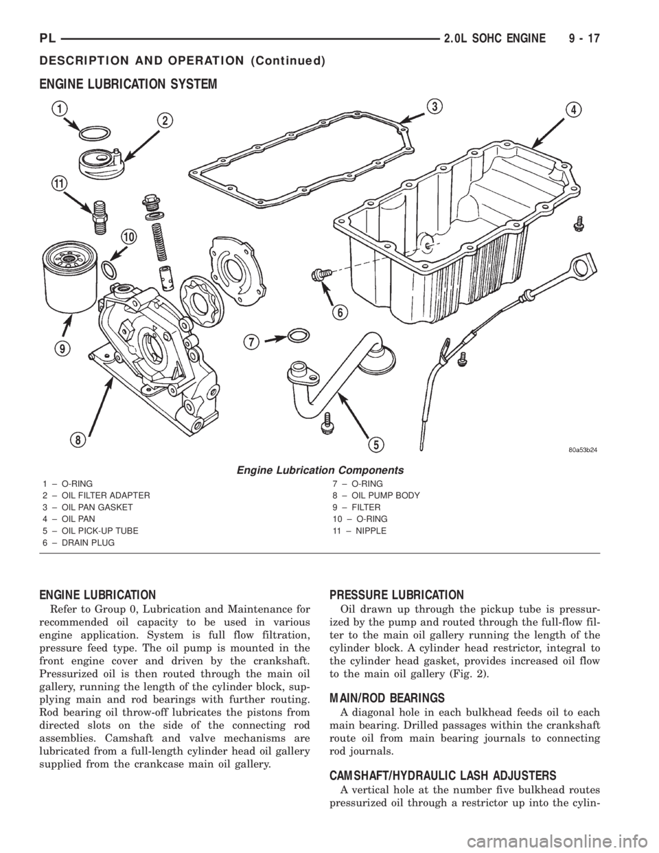
ENGINE LUBRICATION SYSTEM
ENGINE LUBRICATION
Refer to Group 0, Lubrication and Maintenance for
recommended oil capacity to be used in various
engine application. System is full flow filtration,
pressure feed type. The oil pump is mounted in the
front engine cover and driven by the crankshaft.
Pressurized oil is then routed through the main oil
gallery, running the length of the cylinder block, sup-
plying main and rod bearings with further routing.
Rod bearing oil throw-off lubricates the pistons from
directed slots on the side of the connecting rod
assemblies. Camshaft and valve mechanisms are
lubricated from a full-length cylinder head oil gallery
supplied from the crankcase main oil gallery.
PRESSURE LUBRICATION
Oil drawn up through the pickup tube is pressur-
ized by the pump and routed through the full-flow fil-
ter to the main oil gallery running the length of the
cylinder block. A cylinder head restrictor, integral to
the cylinder head gasket, provides increased oil flow
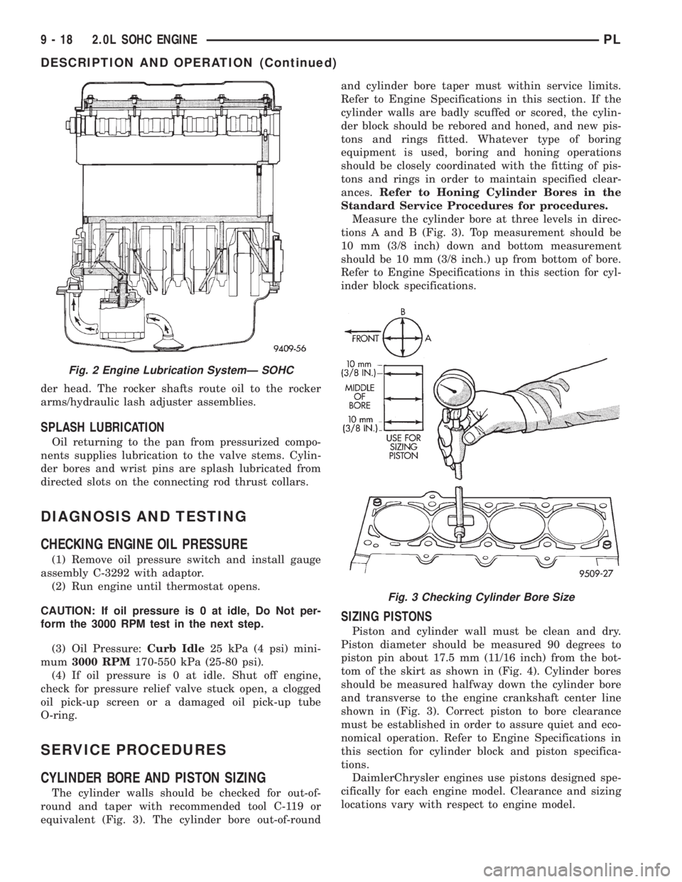
to the main oil gallery (Fig. 2).
MAIN/ROD BEARINGS
A diagonal hole in each bulkhead feeds oil to each
main bearing. Drilled passages within the crankshaft
route oil from main bearing journals to connecting
rod journals.
CAMSHAFT/HYDRAULIC LASH ADJUSTERS
A vertical hole at the number five bulkhead routes
pressurized oil through a restrictor up into the cylin-
Engine Lubrication Components
1 ± O-RING
2 ± OIL FILTER ADAPTER
3 ± OIL PAN GASKET
4 ± OIL PAN
5 ± OIL PICK-UP TUBE
6 ± DRAIN PLUG7 ± O-RING
8 ± OIL PUMP BODY
9 ± FILTER
10 ± O-RING
11 ± NIPPLE
PL2.0L SOHC ENGINE 9 - 17
DESCRIPTION AND OPERATION (Continued)
Page 741 of 1285
der head. The rocker shafts route oil to the rocker
arms/hydraulic lash adjuster assemblies.
SPLASH LUBRICATION
Oil returning to the pan from pressurized compo-
nents supplies lubrication to the valve stems. Cylin-
der bores and wrist pins are splash lubricated from
directed slots on the connecting rod thrust collars.
DIAGNOSIS AND TESTING
CHECKING ENGINE OIL PRESSURE
(1) Remove oil pressure switch and install gauge
assembly C-3292 with adaptor.
(2) Run engine until thermostat opens.
CAUTION: If oil pressure is 0 at idle, Do Not per-
form the 3000 RPM test in the next step.
(3) Oil Pressure:Curb Idle25 kPa (4 psi) mini-
mum3000 RPM170-550 kPa (25-80 psi).
(4) If oil pressure is 0 at idle. Shut off engine,
check for pressure relief valve stuck open, a clogged
oil pick-up screen or a damaged oil pick-up tube
O-ring.
SERVICE PROCEDURES
CYLINDER BORE AND PISTON SIZING
The cylinder walls should be checked for out-of-
round and taper with recommended tool C-119 or
equivalent (Fig. 3). The cylinder bore out-of-roundand cylinder bore taper must within service limits.
Refer to Engine Specifications in this section. If the
cylinder walls are badly scuffed or scored, the cylin-
der block should be rebored and honed, and new pis-
tons and rings fitted. Whatever type of boring
equipment is used, boring and honing operations
should be closely coordinated with the fitting of pis-
tons and rings in order to maintain specified clear-
ances.Refer to Honing Cylinder Bores in the
Standard Service Procedures for procedures.
Measure the cylinder bore at three levels in direc-
tions A and B (Fig. 3). Top measurement should be
10 mm (3/8 inch) down and bottom measurement
should be 10 mm (3/8 inch.) up from bottom of bore.
Refer to Engine Specifications in this section for cyl-
inder block specifications.
SIZING PISTONS
Piston and cylinder wall must be clean and dry.
Piston diameter should be measured 90 degrees to
piston pin about 17.5 mm (11/16 inch) from the bot-
tom of the skirt as shown in (Fig. 4). Cylinder bores
should be measured halfway down the cylinder bore
and transverse to the engine crankshaft center line
shown in (Fig. 3). Correct piston to bore clearance
must be established in order to assure quiet and eco-
nomical operation. Refer to Engine Specifications in
this section for cylinder block and piston specifica-
tions.
DaimlerChrysler engines use pistons designed spe-
cifically for each engine model. Clearance and sizing
locations vary with respect to engine model.
Fig. 2 Engine Lubrication SystemÐ SOHC
Fig. 3 Checking Cylinder Bore Size
9 - 18 2.0L SOHC ENGINEPL
DESCRIPTION AND OPERATION (Continued)
Page 786 of 1285
a 0.762 mm (0.030 in.) spacer under the valve spring
seat to bring spring height back within specification.
(5) Install rocker arm shafts as previously
described in this section.
(6) Checking dry lash. Dry lash is the amount of
clearance that exists between the base circle of an
installed cam and the rocker arm roller when the
adjuster is drained of oil and completely collapsed.
Specified dry lash is 1.17 mm (0.046 in.) for intake
and 1.28 mm (0.050 in.) for exhaust. After performing
dry lash check, refill adjuster with oil and allow 10
minutes for adjuster(s) to bleed down before rotating
cam.
CLEANING AND INSPECTION
INTAKE MANIFOLD
CLEAN AND INSPECT
Check for:
²Inspect manifold for cracks or distortions.
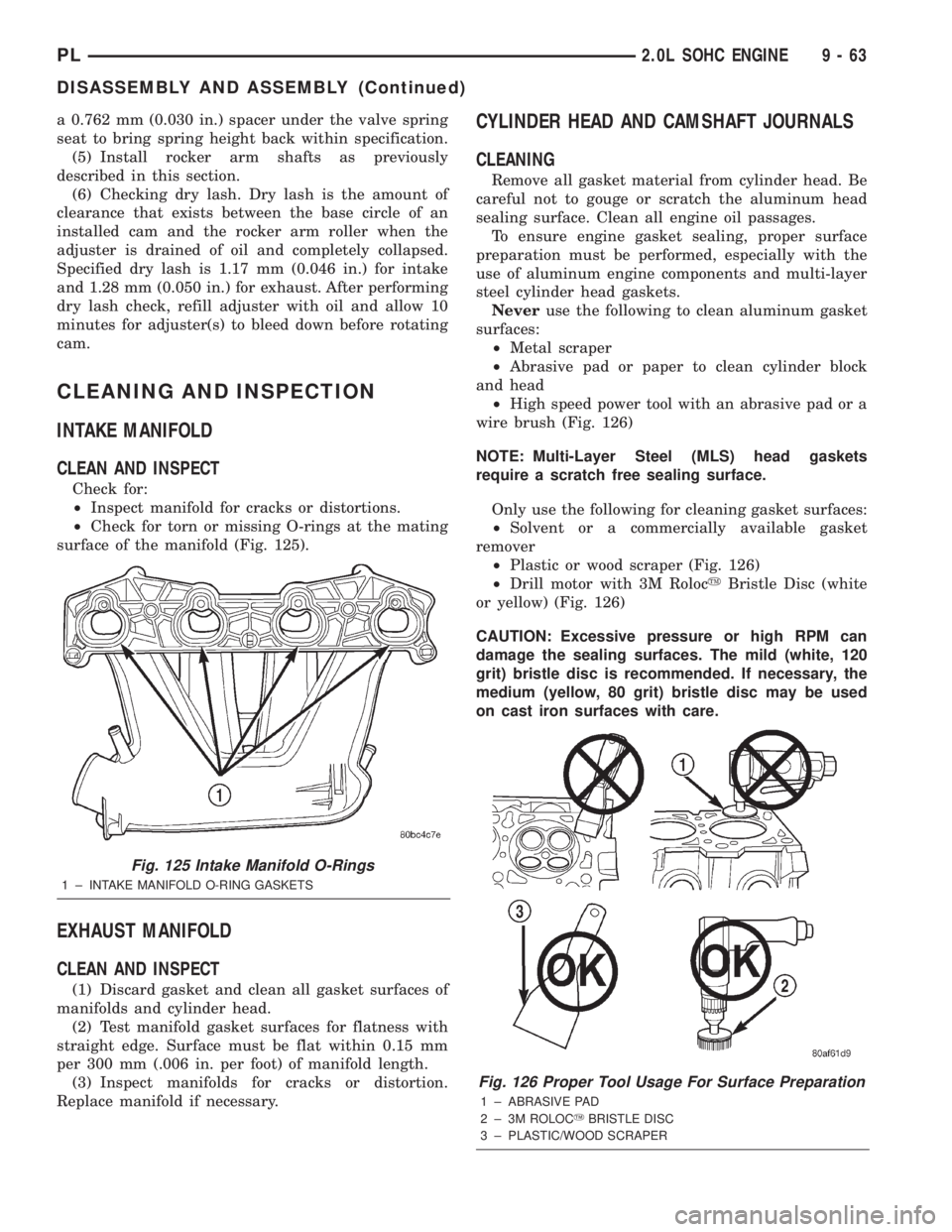
²Check for torn or missing O-rings at the mating
surface of the manifold (Fig. 125).
EXHAUST MANIFOLD
CLEAN AND INSPECT
(1) Discard gasket and clean all gasket surfaces of
manifolds and cylinder head.
(2) Test manifold gasket surfaces for flatness with
straight edge. Surface must be flat within 0.15 mm
per 300 mm (.006 in. per foot) of manifold length.
(3) Inspect manifolds for cracks or distortion.
Replace manifold if necessary.
CYLINDER HEAD AND CAMSHAFT JOURNALS
CLEANING
Remove all gasket material from cylinder head. Be
careful not to gouge or scratch the aluminum head
sealing surface. Clean all engine oil passages.
To ensure engine gasket sealing, proper surface
preparation must be performed, especially with the
use of aluminum engine components and multi-layer
steel cylinder head gaskets.
Neveruse the following to clean aluminum gasket
surfaces:
²Metal scraper
²Abrasive pad or paper to clean cylinder block
and head
²High speed power tool with an abrasive pad or a
wire brush (Fig. 126)
NOTE: Multi-Layer Steel (MLS) head gaskets
require a scratch free sealing surface.
Only use the following for cleaning gasket surfaces:
²Solvent or a commercially available gasket
remover
²Plastic or wood scraper (Fig. 126)
²Drill motor with 3M RolocyBristle Disc (white
or yellow) (Fig. 126)
CAUTION: Excessive pressure or high RPM can
damage the sealing surfaces. The mild (white, 120
grit) bristle disc is recommended. If necessary, the
medium (yellow, 80 grit) bristle disc may be used
on cast iron surfaces with care.
Fig. 125 Intake Manifold O-Rings
1 ± INTAKE MANIFOLD O-RING GASKETS
Fig. 126 Proper Tool Usage For Surface Preparation
1 ± ABRASIVE PAD
2 ± 3M ROLOCYBRISTLE DISC
3 ± PLASTIC/WOOD SCRAPER
PL2.0L SOHC ENGINE 9 - 63
DISASSEMBLY AND ASSEMBLY (Continued)
Page 915 of 1285
ferential case transfers torque from the ring gear to the
drive axles by means of differential side gears.
The NV T350 (A-578) transaxle internal components
can only be serviced by separating the case halves.
CAUTION: The transaxle output shaft is serviced as
a unit. No disassembly and reassembly is possible.
Damage to the transaxle may result.
TRANSAXLE IDENTIFICATION
The transaxle model, part number, build sequence
and date are shown on a bar code label that is
attached to the front of the transaxle. This informa-
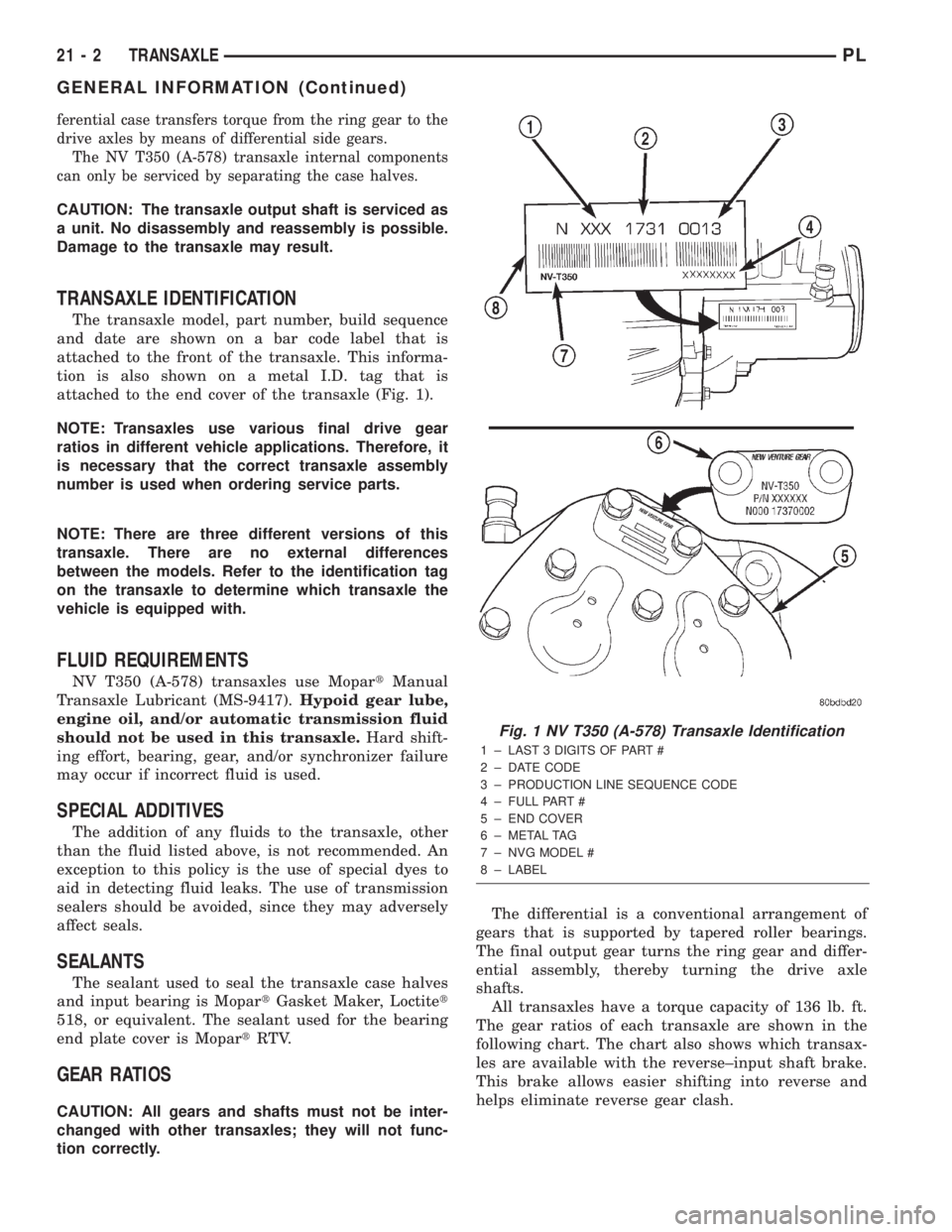
tion is also shown on a metal I.D. tag that is
attached to the end cover of the transaxle (Fig. 1).
NOTE: Transaxles use various final drive gear
ratios in different vehicle applications. Therefore, it
is necessary that the correct transaxle assembly
number is used when ordering service parts.
NOTE: There are three different versions of this
transaxle. There are no external differences
between the models. Refer to the identification tag
on the transaxle to determine which transaxle the
vehicle is equipped with.
FLUID REQUIREMENTS
NV T350 (A-578) transaxles use MopartManual
Transaxle Lubricant (MS-9417).Hypoid gear lube,
engine oil, and/or automatic transmission fluid
should not be used in this transaxle.Hard shift-
ing effort, bearing, gear, and/or synchronizer failure
may occur if incorrect fluid is used.
SPECIAL ADDITIVES
The addition of any fluids to the transaxle, other
than the fluid listed above, is not recommended. An
exception to this policy is the use of special dyes to
aid in detecting fluid leaks. The use of transmission
sealers should be avoided, since they may adversely
affect seals.
SEALANTS
The sealant used to seal the transaxle case halves
and input bearing is MopartGasket Maker, Loctitet
518, or equivalent. The sealant used for the bearing
end plate cover is MopartRTV.
GEAR RATIOS
CAUTION: All gears and shafts must not be inter-
changed with other transaxles; they will not func-
tion correctly.The differential is a conventional arrangement of
gears that is supported by tapered roller bearings.
The final output gear turns the ring gear and differ-
ential assembly, thereby turning the drive axle
shafts.
All transaxles have a torque capacity of 136 lb. ft.
The gear ratios of each transaxle are shown in the
following chart. The chart also shows which transax-
les are available with the reverse±input shaft brake.
This brake allows easier shifting into reverse and
helps eliminate reverse gear clash.
Fig. 1 NV T350 (A-578) Transaxle Identification
1 ± LAST 3 DIGITS OF PART #
2 ± DATE CODE
3 ± PRODUCTION LINE SEQUENCE CODE
4 ± FULL PART #
5 ± END COVER
6 ± METAL TAG
7 ± NVG MODEL #
8 ± LABEL
21 - 2 TRANSAXLEPL
GENERAL INFORMATION (Continued)
Page 983 of 1285
LOW AND REVERSE SERVO (REAR)
Direct air pressure into LOW/REVERSE SERVO
APPLY passage. Operation of servo is indicated by a
tightening of rear band. Spring tension on servo pis-
ton should release the band.
If clutches and servos operate properly, no upshift
indicates that a malfunction exists in the valve body.
FLUID LEAKAGE-TRANSAXLE TORQUE
CONVERTER HOUSING AREA
(1) Check for source of leakage.
(2) Since fluid leakage near the torque converter
area may be from an engine oil leak, the area should
be checked closely. Factory fill fluid is dyed red and,
therefore, can be distinguished from engine oil.
(3) Prior to removing the transaxle, perform the
following checks:
(4) When leakage is determined to originate from
the transaxle, check fluid level prior to removal of
the transaxle and torque converter.
(5) High oil level can result in oil leakage out the
vent in the dipstick. If the fluid level is high, adjust
to proper level.
(6) After performing this operation, inspect for
leakage. If a leak persists, perform the following
operation on the vehicle. This will determine if the
torque converter or transaxle is leaking.
TORQUE CONVERTER LEAKAGE
Possible sources of torque converter leakage are:
²Torque converter weld leaks at the outside diam-
eter (peripheral) weld
²Torque converter hub weld
²Torque converter impeller shell cracked adjacent
to hub
²At drive lug welds
NOTE: Hub weld is inside and not visible. Do not
attempt to repair. Replace torque converter.
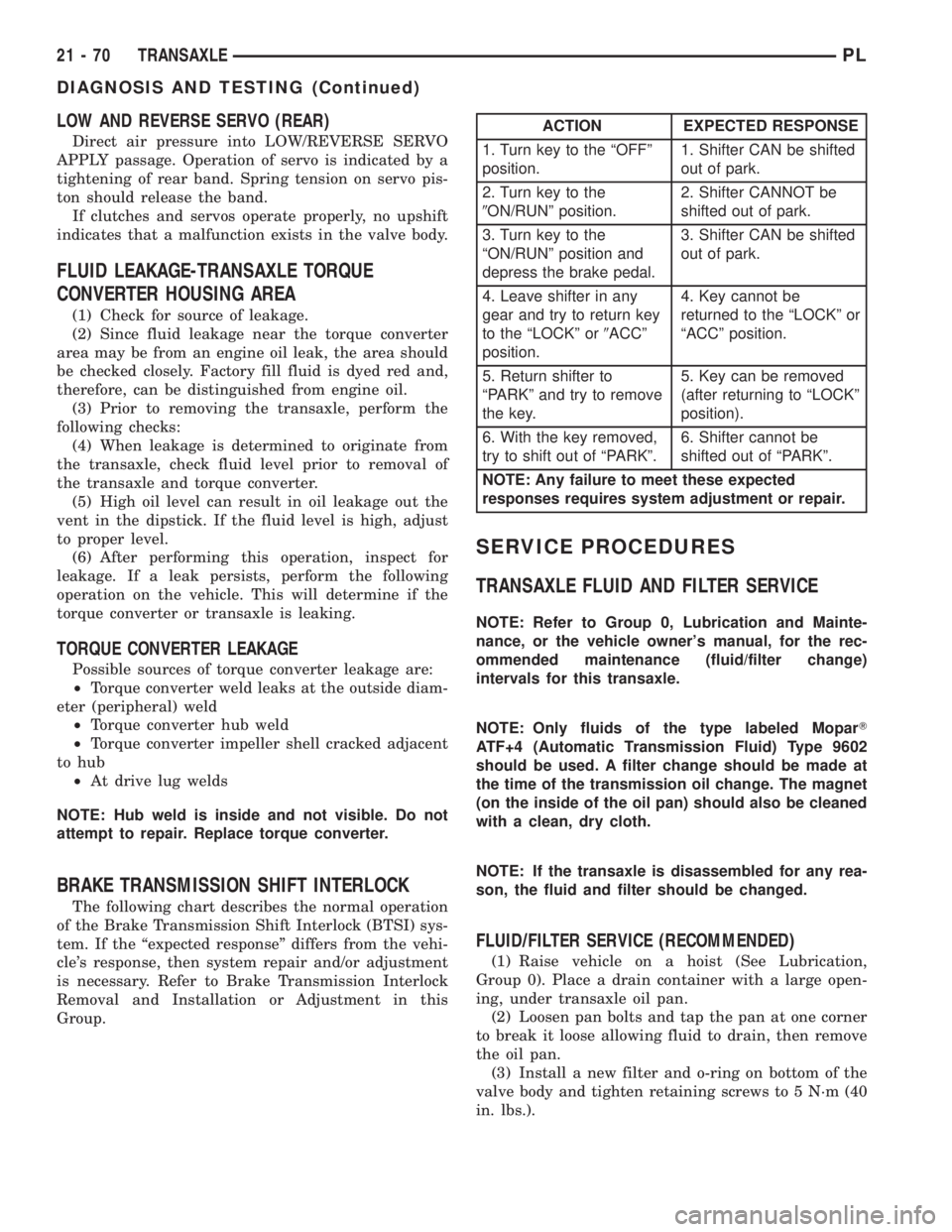
BRAKE TRANSMISSION SHIFT INTERLOCK
The following chart describes the normal operation
of the Brake Transmission Shift Interlock (BTSI) sys-
tem. If the ªexpected responseº differs from the vehi-
cle's response, then system repair and/or adjustment
is necessary. Refer to Brake Transmission Interlock
Removal and Installation or Adjustment in this
Group.
SERVICE PROCEDURES
TRANSAXLE FLUID AND FILTER SERVICE
NOTE: Refer to Group 0, Lubrication and Mainte-
nance, or the vehicle owner's manual, for the rec-
ommended maintenance (fluid/filter change)
intervals for this transaxle.
NOTE: Only fluids of the type labeled MoparT
ATF+4 (Automatic Transmission Fluid) Type 9602
should be used. A filter change should be made at
the time of the transmission oil change. The magnet
(on the inside of the oil pan) should also be cleaned
with a clean, dry cloth.
NOTE: If the transaxle is disassembled for any rea-
son, the fluid and filter should be changed.
FLUID/FILTER SERVICE (RECOMMENDED)
(1) Raise vehicle on a hoist (See Lubrication,
Group 0). Place a drain container with a large open-
ing, under transaxle oil pan.
(2) Loosen pan bolts and tap the pan at one corner
to break it loose allowing fluid to drain, then remove
the oil pan.
(3) Install a new filter and o-ring on bottom of the
valve body and tighten retaining screws to 5 N´m (40
in. lbs.).
ACTION EXPECTED RESPONSE
1. Turn key to the ªOFFº
position.1. Shifter CAN be shifted
out of park.
2. Turn key to the
9ON/RUNº position.2. Shifter CANNOT be
shifted out of park.
3. Turn key to the
ªON/RUNº position and
depress the brake pedal.3. Shifter CAN be shifted
out of park.
4. Leave shifter in any
gear and try to return key
to the ªLOCKº or9ACCº
position.4. Key cannot be
returned to the ªLOCKº or
ªACCº position.
5. Return shifter to
ªPARKº and try to remove
the key.5. Key can be removed
(after returning to ªLOCKº
position).
6. With the key removed,
try to shift out of ªPARKº.6. Shifter cannot be
shifted out of ªPARKº.
NOTE: Any failure to meet these expected
responses requires system adjustment or repair.
21 - 70 TRANSAXLEPL
DIAGNOSIS AND TESTING (Continued)
Page 984 of 1285
(4) Clean the oil pan and magnet. Reinstall pan
using new Mopar Silicone Adhesive sealant. Tighten
oil pan bolts to 19 N´m (165 in. lbs.).
(5) Pour four quarts of MopartATF+4 (Automatic
Transmission Fluid) Type 9602 through the dipstick
opening.
(6) Start engine and allow to idle for at least one
minute. Then, with parking and service brakes
applied, move selector lever momentarily to each
position, ending in the park or neutral position.
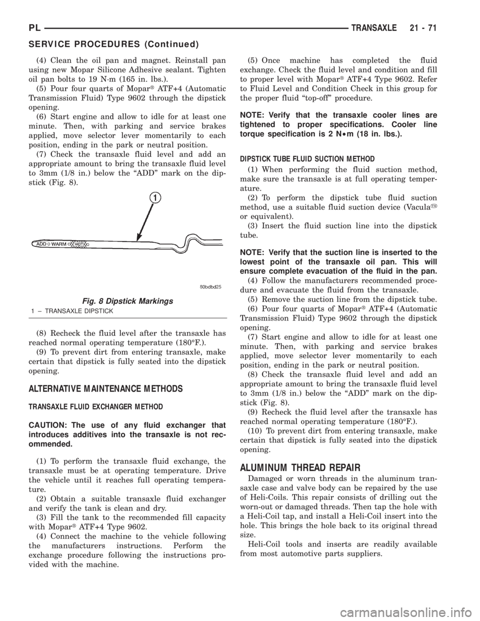
(7) Check the transaxle fluid level and add an
appropriate amount to bring the transaxle fluid level
to 3mm (1/8 in.) below the ªADDº mark on the dip-
stick (Fig. 8).
(8) Recheck the fluid level after the transaxle has
reached normal operating temperature (180ÉF.).
(9) To prevent dirt from entering transaxle, make
certain that dipstick is fully seated into the dipstick
opening.
ALTERNATIVE MAINTENANCE METHODS
TRANSAXLE FLUID EXCHANGER METHOD
CAUTION: The use of any fluid exchanger that
introduces additives into the transaxle is not rec-
ommended.
(1) To perform the transaxle fluid exchange, the
transaxle must be at operating temperature. Drive
the vehicle until it reaches full operating tempera-
ture.
(2) Obtain a suitable transaxle fluid exchanger
and verify the tank is clean and dry.
(3) Fill the tank to the recommended fill capacity
with MopartATF+4 Type 9602.
(4) Connect the machine to the vehicle following
the manufacturers instructions. Perform the
exchange procedure following the instructions pro-
vided with the machine.(5) Once machine has completed the fluid
exchange. Check the fluid level and condition and fill
to proper level with MopartATF+4 Type 9602. Refer
to Fluid Level and Condition Check in this group for
the proper fluid ªtop-offº procedure.
NOTE: Verify that the transaxle cooler lines are
tightened to proper specifications. Cooler line
torque specification is 2 N²m (18 in. lbs.).
DIPSTICK TUBE FLUID SUCTION METHOD
(1) When performing the fluid suction method,
make sure the transaxle is at full operating temper-
ature.
(2) To perform the dipstick tube fluid suction
method, use a suitable fluid suction device (Vaculay
or equivalent).
(3) Insert the fluid suction line into the dipstick
tube.
NOTE: Verify that the suction line is inserted to the
lowest point of the transaxle oil pan. This will
ensure complete evacuation of the fluid in the pan.
(4) Follow the manufacturers recommended proce-
dure and evacuate the fluid from the transaxle.
(5) Remove the suction line from the dipstick tube.
(6) Pour four quarts of MopartATF+4 (Automatic
Transmission Fluid) Type 9602 through the dipstick
opening.
(7) Start engine and allow to idle for at least one
minute. Then, with parking and service brakes
applied, move selector lever momentarily to each
position, ending in the park or neutral position.
(8) Check the transaxle fluid level and add an
appropriate amount to bring the transaxle fluid level
to 3mm (1/8 in.) below the ªADDº mark on the dip-
stick (Fig. 8).
(9) Recheck the fluid level after the transaxle has
reached normal operating temperature (180ÉF.).
(10) To prevent dirt from entering transaxle, make
certain that dipstick is fully seated into the dipstick
opening.
ALUMINUM THREAD REPAIR
Damaged or worn threads in the aluminum tran-
saxle case and valve body can be repaired by the use
of Heli-Coils. This repair consists of drilling out the
worn-out or damaged threads. Then tap the hole with
a Heli-Coil tap, and install a Heli-Coil insert into the
hole. This brings the hole back to its original thread
size.
Heli-Coil tools and inserts are readily available
from most automotive parts suppliers.
Fig. 8 Dipstick Markings
1 ± TRANSAXLE DIPSTICK
PLTRANSAXLE 21 - 71
SERVICE PROCEDURES (Continued)
Page 985 of 1285
FLUSHING COOLERS AND TUBES
When a transaxle failure has contaminated the
fluid, the transaxle oil cooler(s) must be flushed (both
radiator and remote). The cooler bypass valve in the
transaxle must be replaced also. The torque con-
verter must also be replaced with an exchange unit.
This will ensure that metal particles or sludged oil
are not later transferred back into the reconditioned
(or replaced) transaxle.
The recommended procedure for flushing the cool-
ers and tubes is to use Tool 6906A Cooler Flusher.
WARNING: WEAR PROTECTIVE EYEWEAR THAT
MEETS THE REQUIREMENTS OF OSHA AND ANSI
Z87.1±1968. WEAR STANDARD INDUSTRIAL RUB-
BER GLOVES.
KEEP LIT CIGARETTES, SPARKS, FLAMES, AND
OTHER IGNITION SOURCES AWAY FROM THE
AREA TO PREVENT THE IGNITION OF COMBUSTI-
BLE LIQUIDS AND GASES. KEEP A CLASS (B) FIRE
EXTINGUISHER IN THE AREA WHERE THE
FLUSHER WILL BE USED.
KEEP THE AREA WELL VENTILATED.
DO NOT LET FLUSHING SOLVENT COME IN CON-
TACT WITH YOUR EYES OR SKIN: IF EYE CONTAM-
INATION OCCURS, FLUSH EYES WITH WATER FOR
15 TO 20 SECONDS. REMOVE CONTAMINATED
CLOTHING AND WASH AFFECTED SKIN WITH
SOAP AND WATER. SEEK MEDICAL ATTENTION.
COOLER FLUSH USING TOOL 6906A
(1) Remove cover plate filler plug on Tool 6906A.
Fill reservoir 1/2 to 3/4 full of fresh flushing solution.
Flushing solvents are petroleum based solutions gen-
erally used to clean automatic transmission compo-
nents.DO NOTuse solvents containing acids, water,
gasoline, or any other corrosive liquids.
(2) Reinstall filler plug on Tool 6906A.
(3) Verify pump power switch is turned OFF. Con-
nect red alligator clip to positive (+) battery post.
Connect black (-) alligator clip to a good ground.
(4) Disconnect the cooler lines at the transmission.
NOTE: When flushing transmission cooler and
lines, ALWAYS reverse flush.
(5) Connect the BLUE pressure line to the OUT-
LET (From) cooler line.
(6) Connect the CLEAR return line to the INLET
(To) cooler line
(7) Turn pump ON for two to three minutes to
flush cooler(s) and lines. Monitor pressure readingsand clear return lines. Pressure readings should sta-
bilize below 20 psi. for vehicles equipped with a sin-
gle cooler and 30 psi. for vehicles equipped with dual
coolers. If flow is intermittent or exceeds these pres-
sures, replace cooler.
(8) Turn pump OFF.
(9) Disconnect CLEAR suction line from reservoir
at cover plate. Disconnect CLEAR return line at
cover plate, and place it in a drain pan.
(10) Turn pump ON for 30 seconds to purge flush-
ing solution from cooler and lines. Turn pump OFF.
(11) Place CLEAR suction line into a one quart
container of MopartATF+4 (Automatic Transmission
Fluid) Type 9602.
(12) Turn pump ON until all transmission fluid is
removed from the one quart container and lines. This
purges any residual cleaning solvent from the trans-
mission cooler and lines. Turn pump OFF.
(13) Disconnect alligator clips from battery. Recon-
nect flusher lines to cover plate, and remove flushing
adapters from cooler lines.
OIL PUMP VOLUME CHECK
After the new or repaired transmission has been
installed, fill to the proper level with MopartATF+4
(Automatic Transmission Fluid) Type 9602. The vol-
ume should be checked using the following proce-
dure:
(1) Disconnect theFrom coolerline at the trans-
mission and place a collecting container under the
disconnected line.
CAUTION: With the fluid set at the proper level,
fluid collection should not exceed (1) quart or inter-
nal damage to the transmission may occur.
(2) Run the engineat curb idle speed, with the
shift selector in neutral.
(3) If fluid flow is intermittent or it takes more
than 20 seconds to collect one quart of ATF, discon-
nect theTo Coolerline at the transaxle.
(4) Refill the transaxle to proper level and recheck
pump volume.
(5) If flow is found to be within acceptable limits,
replace the cooler. Then fill transmission to the
proper level, using MopartATF+4 (Automatic Trans-
mission Fluid) Type 9602.
(6) If fluid flow is still found to be inadequate,
check the line pressure using the Transaxle Hydrau-
lic Pressure Test procedure.
21 - 72 TRANSAXLEPL
SERVICE PROCEDURES (Continued)
Page 1086 of 1285
(3) Grasp the wheel cover and pull straight out-
ward. This will remove the wheel cover from the
wheel.
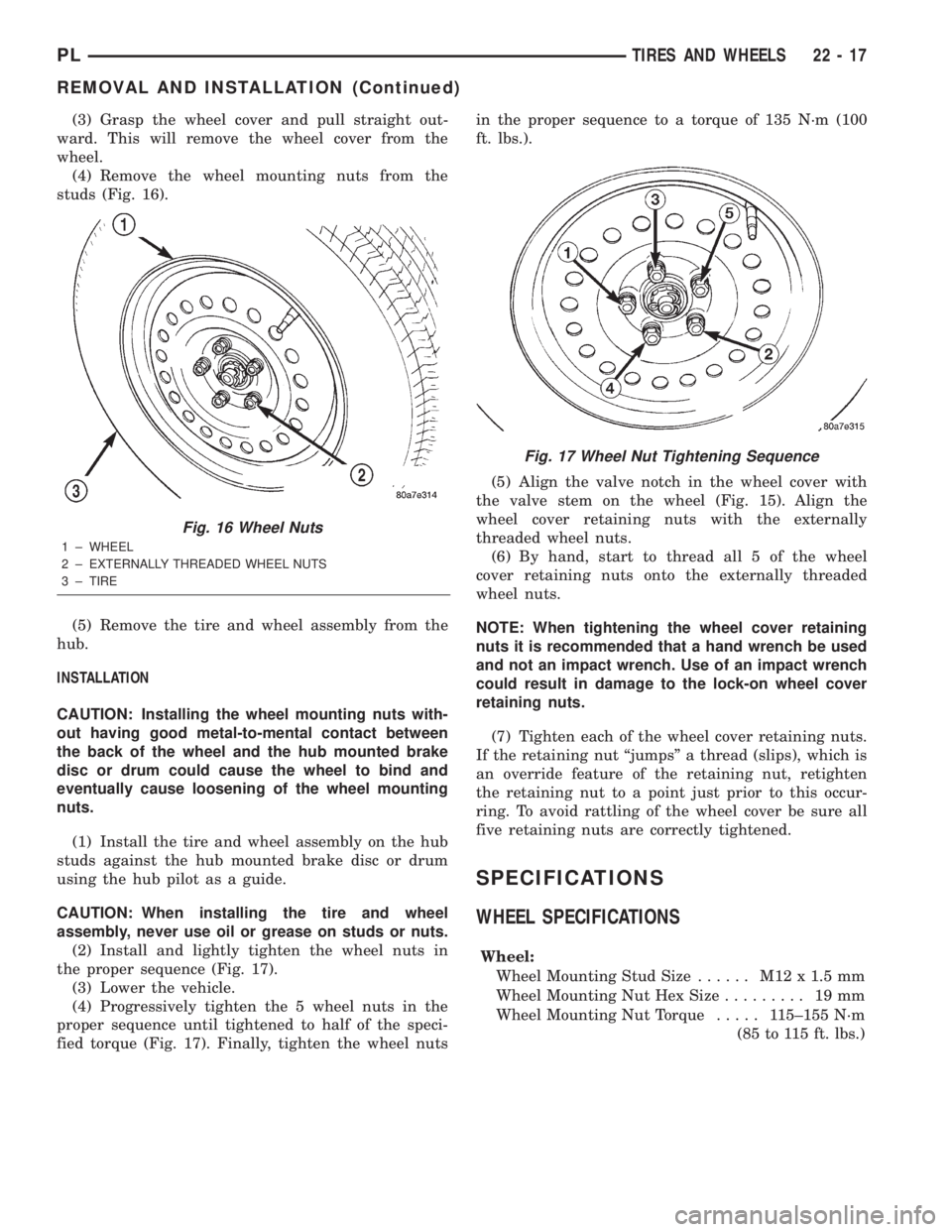
(4) Remove the wheel mounting nuts from the
studs (Fig. 16).
(5) Remove the tire and wheel assembly from the
hub.
INSTALLATION
CAUTION: Installing the wheel mounting nuts with-
out having good metal-to-mental contact between
the back of the wheel and the hub mounted brake
disc or drum could cause the wheel to bind and
eventually cause loosening of the wheel mounting
nuts.
(1) Install the tire and wheel assembly on the hub
studs against the hub mounted brake disc or drum
using the hub pilot as a guide.
CAUTION: When installing the tire and wheel
assembly, never use oil or grease on studs or nuts.
(2) Install and lightly tighten the wheel nuts in
the proper sequence (Fig. 17).
(3) Lower the vehicle.
(4) Progressively tighten the 5 wheel nuts in the
proper sequence until tightened to half of the speci-
fied torque (Fig. 17). Finally, tighten the wheel nutsin the proper sequence to a torque of 135 N´m (100
ft. lbs.).
(5) Align the valve notch in the wheel cover with
the valve stem on the wheel (Fig. 15). Align the
wheel cover retaining nuts with the externally
threaded wheel nuts.
(6) By hand, start to thread all 5 of the wheel
cover retaining nuts onto the externally threaded
wheel nuts.
NOTE: When tightening the wheel cover retaining
nuts it is recommended that a hand wrench be used
and not an impact wrench. Use of an impact wrench
could result in damage to the lock-on wheel cover
retaining nuts.
(7) Tighten each of the wheel cover retaining nuts.
If the retaining nut ªjumpsº a thread (slips), which is
an override feature of the retaining nut, retighten
the retaining nut to a point just prior to this occur-
ring. To avoid rattling of the wheel cover be sure all
five retaining nuts are correctly tightened.
SPECIFICATIONS
WHEEL SPECIFICATIONS
Wheel:
Wheel Mounting Stud Size...... M12x1.5mm
Wheel Mounting Nut Hex Size......... 19mm
Wheel Mounting Nut Torque..... 115±155 N´m
(85 to 115 ft. lbs.)
Fig. 16 Wheel Nuts
1 ± WHEEL
2 ± EXTERNALLY THREADED WHEEL NUTS
3 ± TIRE
Fig. 17 Wheel Nut Tightening Sequence
PLTIRES AND WHEELS 22 - 17
REMOVAL AND INSTALLATION (Continued)