2000 AUDI ALLROAD instrument cluster
[x] Cancel search: instrument clusterPage 120 of 306

--------------------CONTROLS AND EQUIPMENT
Warning light
If the coolant warning light m the Auto
Check System (see page 141) flashes when
driving, the engine may be overheated be
cause of low coolant level.
Note
Do not install accessories (addi
tional lights or Insect screens. for
example) on top of the front bumper.
They may restrict engine cooling
and cause engine damage.
Always heed all WA RNINGS
on page 142 and 232. 5
- Fuel gauge
iU
The fuel gauge works when the ignition is
switched on.
The fuel tank capacity is approximately 18.5
gallons (70 liters).
When the needle reaches the red area
there is a reserve of about 2.4 U.S. gallon �
(9 liters) of fuel left in the tank. lime to re
fuel.
The fuel pump symbol in the instrument
cluster lights up as an additional reminder to
refuel.
Never run the tank completely dry. See also
page 222. 6
- Speedometer I odometer
Speedometer Refer to "Break-In Period" before driving
off see page 193.
The speedometer indicates the speed.
On U.S. models, the outer row of numbers
� larg ": numbers) indicates the vehicle speed
1n m1les per hour (mph). The inner row
(small numbers) indicates the vehicle
speed in kilometres per hour (km I h).
The arrangement of the instruments in the
c !uster may vary depending on engine ver
SIOn.
119
Page 121 of 306

CONTROLS AND
EQUIPMEN T--------------------
Odometer
The odometer indicates the distance driven.
USA models:
Miles
Canada models: Kilometres
On the trip odometer, the last digit indicates
1 /,0 of a mile or 1 00 meters.
Reset knob for trip odometer
To record a distance, reset the trip odome
ter by pressing the knob until the display re
turns to zero -see illustrat ion.
12 0 When
the ignition is off, the display can be
ill umin ated by pressing the test knob for the
Auto-Check System. See page 116, posi
tion 8. The display switches off automati
cally after about 15 seconds.
Also the display will remain illuminated for
abo �t 30 seconds after you open the driv
er's door.
Defect message
If there is a defect in the instrument cluster,
"dEF" will be displayed continuously in the
trip odometer display area. Have this prob
lem corrected as soon as possible by an au
thorized Audi Dealer.
7 - Vo ltmeter
The voltmeter indicates the voltage for the
vehicle's total electrical system, which
should normally be between 12 and
14 volts. If the display drops below 12 volts
when the engine is running, have the power
supply (battery and alternator) checked by
an authorized Audi Dealer. See also
pages 127 and 143.
The voltage may fall below 8 volts while the
engine is being started. 8
- Set I Check knob
Setting the clock ...• ... .
Auto-ch eck system
Odometer lighting .
Service indicator .. 118
14 0
12 0
121
9 - Driver information system
Auto-C heck System display . . . . . ... 138
Outside air temperature display .... 137
Tr ip computer display . . . . . . . . 146
Selector lever position display ....... 1 07
Radio frequency display . . . . . . 138
Service interval display . . . . . . . . . . .
121
10 -Reset knob
Reset knob for trip odometer . .... .. 12 0
Service indicator . . . . . .. . . . . . . 121
Page 122 of 306
Service
Interval Display
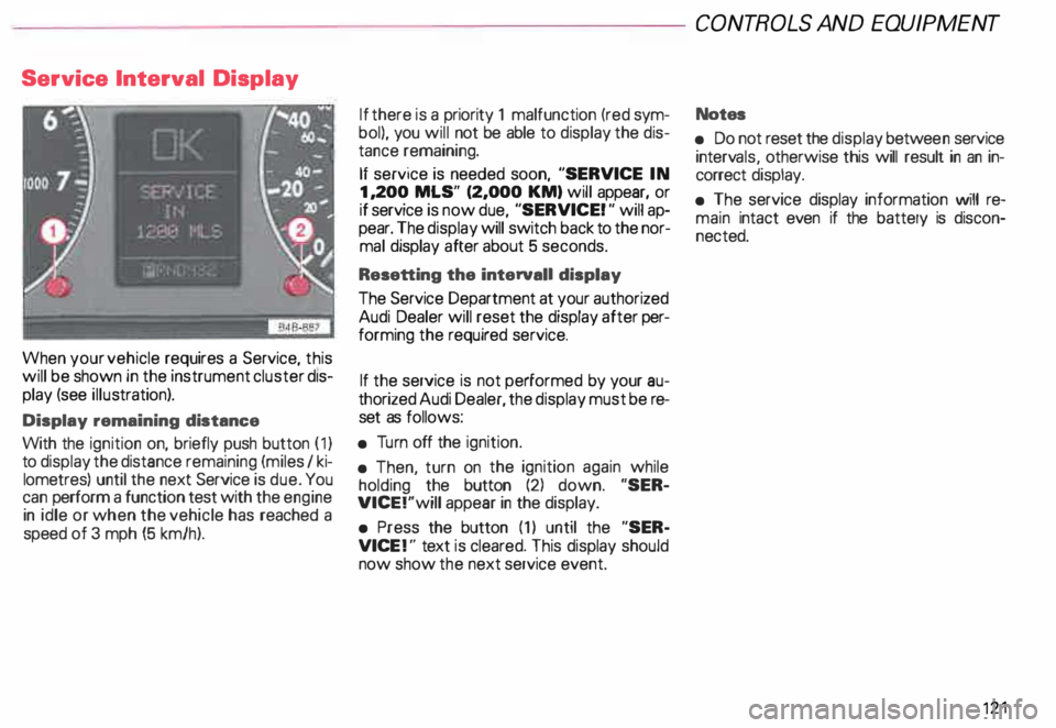
When your vehicle requires a Service, this
will be shown in the instrument cluster dis
play (see illustration).
Display remaining distance
With the ignition on, briefly push button (1)
to display the distance remaining (miles I ki
lometres) until the next Service is due. You
can perform a function test with the engine
in idle or when the vehicle has reached a
speed of 3 mph (5 km/h). If
there is a priority 1 malfunction (red sym
bol), you will not be able to display the dis
tance remaining.
If service is needed soon, "SERVICE IN
1, 200 MLS" (2,000 KM) will appear, or
if service is now due, "SERVICE! " will ap
pear. The display will switch back to the nor
mal display after about 5 seconds.
Resetting the interval! display
The Service Department at your authorized
Audi Dealer will reset the display after per
forming the required service.
If the service is not performed by your au
thorized Audi Dealer, the display must be re
set as follows:
• Turn off the ignition.
• Then, turn on the ignition again while
holding the button (2) down. "SER
VICE!"will appear in the display.
• Press the button (1) until the "SER
VICE !" text is cleared. This display should
now show the next service event. CONT
ROLS AND EQUIPMENT
Notes
• Do not reset the display betwee n service
interv als, otherwise this will result in an in
correct display.
• The service display information will re
main intact even if the battery is discon
nected. 121
Page 128 of 306
f4
WARNING continued
• If the brake warning light does
not go out with the engine running
and the parking brake released, or
lights up while you ere driving, the
fluid level in the brake fluid reser
voir is too low.
• If you believe that it Is safe to do
so, proceed immediately at low
speed to the nearest authorized
Audi Dealer or qualified workshop
and have the brake system in
spected.
• Please be very careful and be
sure to remember that after sev
eral brake applications, you will
need greater pressure on the brake
pedal to stop your vehicle. Conse
quently, you must allow for in
creased braking distances. Trying
to brake as quickly as usual could
lead to an accident.
For details see "Brakes.. on page
201. Generator
This
light comes on when the ignition is
turned on and goes out after the engine is
started. If the light does not go out after
star ting and rewing up the engine momen
tarily or lights up while driving, there may be
a malfunc tion in the electrical system, or the
V- belt driving the gener ator may be broken. A If the warning light comes on
V while driving, stop the vehicle
and turn oft the engine. Inspect the
belts.
If the V-belt is not torn, you can still continue
driving to the nearestAudi Dealer. However,
since the battery is no longer being charged,
switch off all unne cessary electrical equip
ment.
If the V- belt is tom, the power steering and
the radiator fan will also not work.
Obtain expert assistance.
g Always heed all WA RNINGS
r!!l on page 232, chapter "En
gine compartment '". CONT
ROLS AND EQ UIPMENT
Safety belts
Yo ur vehicle has a warning light to remind
you to wear your safety belt and to make
sure that others do too.
After switching on the ignition, the warning
light in the instrument cluster will come on
for about 6 seconds along with a war ning
tone. As soon as you fasten your safety belt,
the warning tone will stop.
The warning light, however, will be on for
the entire 6 seconds.
Fasten your safety belt now and ma
ke sure that your passengers also
properly put on their safety belts.
Please be sure to read the chapter
"Safety belts" page 14.
127
Page 139 of 306

CONT
ROLS AND EQUIPMEN T-------------------------------------------
Radio frequency display
If the radio is switched on and no second
priority faults are present, the OK symbol
will go out and the display will show the fre
quenc y selected and various other informa
tion. This feature depends on the type of ra
dio fitted.
These displays are in addition to the radio
display -see separate operating instruc
tions for radio.
13 8 Auto-Check
system
In addition to the warning lights the Auto
Check System consistently monitors cer
tain individual functions and components of
the vehicle as soon as the ignition is turned
on and when the vehicle is moving.
Malfunctions or urgent repairs are audi bly
signaled as well as displayed by red (prior
ity 1) or yellow (priority 2) light symbols in
the instrument cluster.
You are thus reminded that a problem exists
which should be corrected for your conve
nience and safety, and to prevent the risk of
considerable damage to your vehicle due to
cert ain malfunctions.
The Auto-Check System incorporates a
speed warning feature and is also used
to display certain radio information_
The following malfunctions or warnings can
be displayed: Red Symbols (priority
1)
Engine coolant level is too low/
Engine temperature is too high
(moving symbol).
Engine oil pressure is too low
(moving symbol).
Page 147 of 306
CONT
ROLS AND EQUIPMENT---------------------
Trip computer
This feature generates much helpful infor
mation by simple touch control. For the driv
er's convenience, the computer's memory
display window is integrated in the instru
ment cluster.
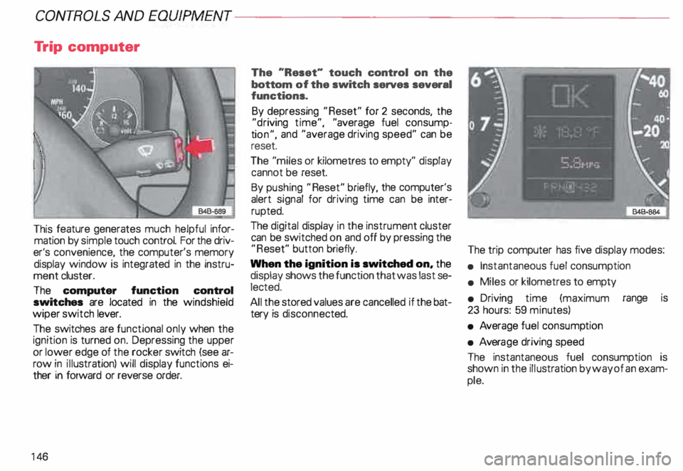
The computer function control
switches are located in the windshield
wiper switch lever.
The switches are functional only when the
ignition is turned on. Depressing the upper
or lower edge of the rocker switch (see ar
row in illustration) will display functions ei
ther in forward or reverse order.
14 6 The
"Reset" touch control on the
bottom of the switch serves several
functions.
By depressing "Reset" for 2 seconds, the
"d riving time", "average fuel consump
ti on", and "average driving speed" can be
reset.
The "miles or kilometres to empty" display
cannot be reset.
By pushing "Reset" briefly, the computer's
alert signal for driving time can be inter
rupted.
The digital display in the instrument cluster
can be switched on and off by pressing the
"R eset" button briefly.
When the ignition is switched on, the
display shows the function that was last se
lected.
All the stored values are cancelled if the bat
tery is disconne cted. The
trip computer has five display modes:
• Instantaneous fuel consumption
• Miles or kilometres to empty
• Driving time (maximum range is
23 hours: 59 minutes)
• Average fuel consump tion
• Avera ge driving speed
The instantaneous fuel consumption is
shown in the illustration by way of an exam
ple.
Page 150 of 306
Front
fog lights
�D
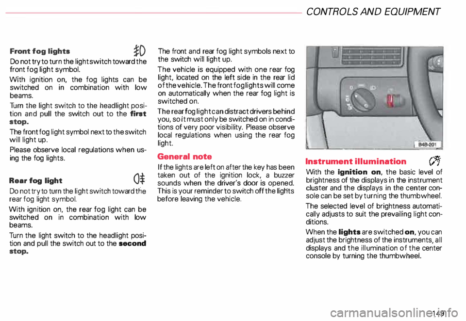
Do not try to turn the light switch toward the
front fog light symbol.
With ignition on, the fog lights can be
switched on in combination with low
beams.
Tu rn the light switch to the headlight posi
tion and pull the switch out to the fint
stop.
The front fog light symbol next to the switch
will light up.
Please observe local regulations when us
ing the fog lights.
Rear fog light
0$
Do not try to turn the light switch toward tlie
rear fog light symbol.
With ignition on. the rear fog light can be
switc hed on in combination with low
beams.
Tu rn the light switch to the headlight posi
tion and pull the switch out to the second
stop. The front
and rear fog light symbols next to
the switch will light up.
The vehicle is equipped with one rear fog
light, located on the left side in the rear lid
of the vehicle. The front fog lights will come
on automatically when the rear fog light is
switched on.
The rear fog light can distract drivers behind
you, so it must only be switched on in condi
tions of very poor visibil ity. Please observe
local regulations when using the rear fog
light.
General note
If the lights are left on after the key has been
taken out of the ignition lock, a buzzer
sounds when the driver's door is opened.
This is your reminder to switch off the ligHts
before leaving the vehicle. CONT
ROLS AND EQUIPMEN T
Instrument illumination
(;,.
With the Ignition on, the basic level of
brightness of the displays in the instrument
cluster and the displays in the center con
sole can be set by turning the thumbwheel.
The selected level of brightness automati
cally adjusts to suit the prevailing light con
ditions.
When the lights are switched on, you can
adjust the brightness of the instruments all
displays and the illumination of the ce�ter
console by turning the thumbwheel.
149
Page 156 of 306
---------------------CONTROLS AND EQUIPMEN T
Notes continued
• At excessive loads (for example, over
heating caused by frequent changes in the
ride height when the vehicle is stationary),
the system is temporarily deactivated for
safety reasons. The system will return to
full operation once it has cooled down.
• The system automatically switches to
the normal level if the ESP automatically
shuts off (see page 205). If this happens,
switch the ignition off, and then on again.
Now you can select the desired level once
again.
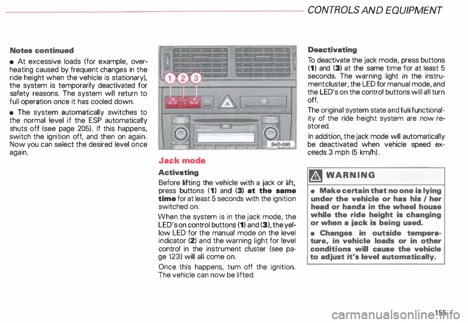
Jack mode
Activating Before lifting the vehicle with a jack or lift,
press buttons (1) and (3) at the same
time for at least 5 seconds with the ignition
switched on.
When the system is in the jack mode, the
LED's on control buttons (1) and (3), the yel
low LED for the manual mode on the level
ind icator (2) and the warning light for level
control in the instrument cluster (see pa
ge 123) will all come on.
Once this happens, tum off the ignition.
The vehicle can now be lifted. Deactivating
To deactivate the jack mode, press buttons
(1) and (3) at the same time for at least 5
seconds. The warning light in the instru
ment cluster, the LED for manual mode, and
the LED's on the control buttons will all turn
off.
The original system state and full functional�
ity of the ride height system are now re
stored.
In addition, the jack mode will automatically
be deactivated when vehicle speed ex
ceec;ls 3 mph (5 km/h ).
�W ARNING
• Make certain that no one is lying
under the vehicle or has his I her
head or hands in the wheel house
while the ride height is changing
or when a iack is being used.
• Changes in outside tempera
ture, in vehicle loads or in other
conditions will cause the vehicle
to adjust it's level automatically.
155