2000 AUDI ALLROAD clock
[x] Cancel search: clockPage 32 of 306
-----------------------------------------------------SAFETY RRST
�W ARNING
• Never sit closer than 10 inches
(25 em) to the stee ring wheel.
• If you cannot sit more than
10 inches (25 em) from the steer
ing wheel, we recommend that
you investigate whether adaptive
equipment may be available to
help you reach the pedals and in
crease your seating distance from
the steering wheel.
Adjusting the steering wheel
For detailed steps for adjusting the steering
wheel please see "Adjustable steering col
umn" page 98.
Adjust the steering wheel so that the steer
ing wheel and airbag cover points at your
chest and not at your face. The steer ing
wheel should be adjusted so that you can
hold the outer rim of the steering wheel
comfortably with your hands at the 3 o'clock
and 9 o'clock positions. �W
ARNING
• Pointing the steering wheel to
ward your face decreases the abil
ity of the supplementa l driver's air
bag to protect you in an accident.
• Holding the steering wheel the
wrong way can cause serious inju
ries to the hands, arms and head if
the driver's airbag inflates.
• Never hold the steering wheel at
the 12 o'clock position or with
your hands at other positions in
side the steering wheel rim or on
the steering wheel hub.
Adjusting the passenger's seat
For detailed steps for adjusting the pas
senger's seat please see "Front Seats" on
page 76.
We recommend that you adjust the passen
ger's seat as follows:
- backrest upright (never reclined)
place your feet on the floor in front of the
passenger's seat adjust
the passenger's seat as far as pos
sible to the rear of the fore and aft adjust-
1)1ent range.
�W ARNING
• Always keep both feet on the
floor in front of the seat.
• Never place your feet on the in
strument panel or on the seat. If
the airbag inflates and your feet
are on the instrument panel or on
the seat, your could receive seri
ous personal injuries.
Some other important points to
know
Because airbags inflate in the blink of an eye
with great force, things you have on your lap
or have placed on the seat could become
dangerous projectiles and be pushed into
you if the airbag inflates.
Always head all WARNINGS
on next page.
31
Page 100 of 306
---------------------CONTROLS
AND EQUIPMEN T
U WARNING continued
• The front seats must not be
pushed too close to the steering
wheel or to the instrument panel.
Never sit closer than 10 inches
(25 em) to the steering wheel.
• If you cannot sit more than
1 0 inches (26 em) from the steer
ing wheel, we recommend that
you investigate whether adaptive
equipment may be available to
help you reach the pedals and in
crease your seating distance from
the stee ring wheel.
• Pointing the stee ring wheel to
ward your face decreases the abil
ity of the supplemental driver's air
bag to protect you in an accident. �
WARNING continued
• Always hold the steering wheel
on the outside of the steering
wheel rim with your hands at the
9 o'clock and 3 o'clock positions
to help reduce the risk of personal
injury if the driver's airbag in
flates.
• Never hold the steering wheel at
the 12 o'clock position or with
your hands at other positions in·
side the steering wheel rim or on
the stee ring wheel hub.
• Holding the steering wheel the
wrong way can cause serious inju
ries to the hands. arms and head if
the driver's airbag inflates. Electrically
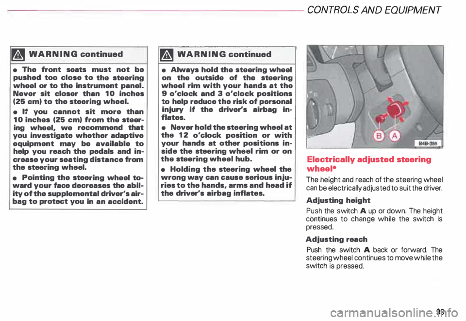
adjusted steering
wheel*
The height and reach of the steering wheel
can be electrically adjusted to suit the driver.
Adjusting height
Push the switch A up or down. The height
continues to change while the switch is
pressed.
Adjusting reach
Push the switch A back or forward. The
steering wheel continues to move while the
switch is pressed.
99
Page 101 of 306
CONT
ROLS AND
EQUIPMEN T---------------------
BBN-163 I
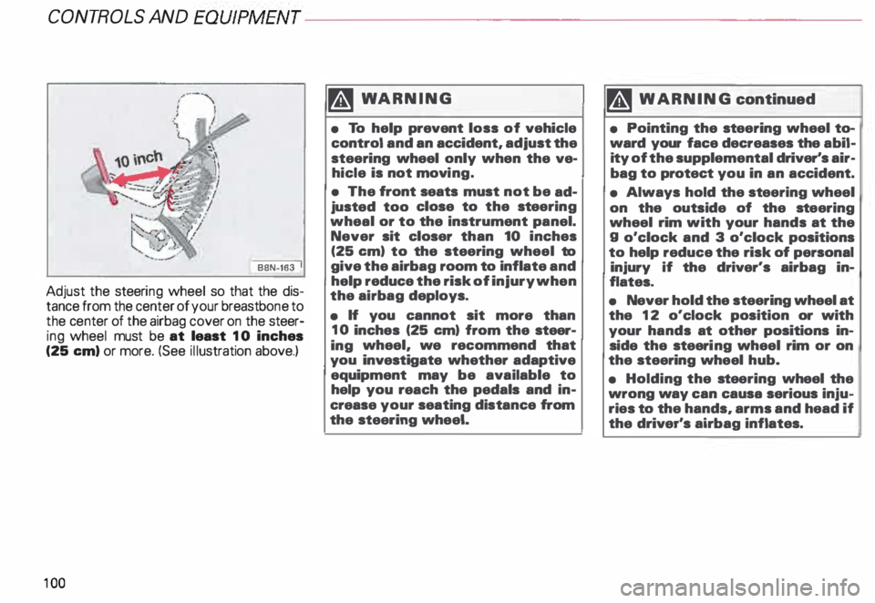
Adjust the steeri ng wheel so that the dis
tance from the center of your breastb one to
the center of the airbag cover on the steer
ing wheel must be at least 10 inches
(25 em) or more. (See illustration above.)
10 0 �W
ARNING
• To help prevent loss of vehicle
control and an accident, adjust the
steering wheel only when the ve
hicle is not movi ng.
• The front seats must not be ad
justed too close to the steering
wheal or to the instrument panel.
Never sit closer than 10 inches
(25 em) to the steering wheel to
give the airbag room to inflate and
help reduce the risk of injury when
the airbag deploys.
• If you cannot sit more than
10 inches (25 em) from the steer
ing wheel, we recommend that
you investigate whether adaptive
equipment may be available to
help you reach the pedals and in
crease your seating distance from
the steering wheel. '4
WARNING continued
• Pointing the stee ring wheel to
ward your face decreases the abil
ity of the supplemental driver's air
bag to protect you in an accident.
• Always hold the st eering wheel
on the outside of the steering
wheel rim with your hands at the
g o'clock and 3 o'clock positions
to help reduce the risk of personal
injury if the driver's airbag in
flates.
• Never hold the steering wheel at
the 12 o'clock position or with
your hands at other positions in
side the steeri ng wheel rim or on
the steering wheel hub.
• Holding the steering wheel the
wrong way can causa serious inju
ries to the hands, arms and head if
the driver's airbag inflates.
Page 117 of 306

CONTROLS AND EQUIPMENT---------------------
Instrument cluster
Pos. see page
1 - Engine oil temperature gauge ... 117
2 - Tachometer ...... ........... .. 117
with digital clock and date display 117
3- Warning I ind icator lights ..... .. 122
4 - Engine coolant temperature gauge 118
5- Fuel gauge
119 Pos.
6 · Speedometer
with odometer,
trip odometer display ... .
7 - Vo ltmeter ............ .
8 - Set I check knob for see
page
119
12 0
12 0
Setting the clock . . . . . .
118
Auto -check system ............ 140
Clock and Odometer lighting .... 12 0
Service indicator . . . . . . . . . . . . . . 121 Pos.
see page
9 - Driver information system
Auto-C heck System display . . . . 138
Outside air temperature display .
137
Trip computer display . . . . . . . . 146
Selector lever position display . .
1 07
Radio frequency display ........ 138
Service interval display . . . . . . 121
1 0 -Reset knob for
Trip odometer ......•.. _ ..... .. 120
Service indicator . . . . . . . . . . . . 121
Page 118 of 306

The illustration on previous page shows the
arrangement of the instrument cluster in a
U.S. vehicle.
1 - Engine oil temperature
gauge �
Of (C)
Engine oil temperature ranges from 150 OF
(60 °C) to 350 °F (180 °C). With the needle
around 150 °F (60 °C), do not accelerate un
der full load.
If the needle moves into the upper zone in
excepti onal cases, reduce your speed. The
needle should then return to the normal
zone.
If the needle stays in upper zone, stop the
vehicle, switch off the engine and check the
oil leve l. If the oil level is correct and the oil
pressure warning light does not flash when
the engine is started, you can drive to the
next authorized Audi Dealer but do·not run
engine at high speeds. 2
- Ta chometer with clock
Ta chometer
The red area at the end of the scale indi
cates maximum permissible engine rpm
(rev olutions per minute) for all gears after
the break-in period. Before reaching this
area, the next higher gear or selector lever
position "D" should be selected or the foot
eased off the accelerator pedal.
r.Gb Upshifting early saves fuel and
1!/!:i reduces engine noise.
Shift to the next lower gear when engine
rpm drops below 1,500 rpm. CONT
ROLS AND EQUIPMENT
Digital clock with date display
The clock and date are located in the
tachometer dial. Adjusting the clock I date:
see next page.
When the ignition is off the clock I date dis
play can be illuminated by pressing the set
butt on. See illustration above.
117
Page 119 of 306
CONTROLS AND
EQUIPMENT-----------------------------------------
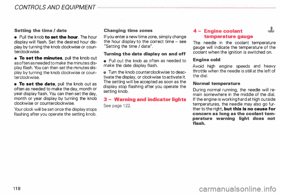
Setting the time I date
• Pull the knob to set the hour. The hour
display will flash. Set the desired hour dis
play by turning the knob clockwise or coun
terclockwise.
• To set the minutes, pull the knob out
as often as needed to make the minutes dis
play flash. You can then set the minutes dis
play by turning the knob clockwise or coun
terclockwise.
• To set the date, pull the knob out as
often as needed to make the day, month or
year display flash. You can then set the day,
month or year display by turning the knob
clockwise or counterclockwise.
Yo ur clock will be set once the display stops
flashing after you operate the setting knob.
118 Changing
time zones
If you enter a new time zone, simply change
the hour display to the correct time -see
"Setting the time I date".
Tu rning the date display on and off
• Pull out the knob as often as needed to
make the date display flash.
o Turn the knob counterclockwise to deac
tivate the display, or clockwise to activate it.
The setting will be accepted as soon as the
display stop flashing after you operate the
setti ng knob.
3 - Warning and indicator lights
See page 122. 4
- Engine coolant -¥
-
temperature gauge
The needle in the coolant temperature
gauge will indicate the temperature of the
coolant when the ignition is switched on.
Engine cold
Avoid high engine speeds and heavy
throttle when the needle is still at the left of
the dial.
Normal temperature
During normal running, the needle will re
main somewhere in the middle of the dial.
If the engine is working hard at high outside
temperatures, the needle may also go fur
ther to the right, but this Is no cause for
concern as long as the coolant tem
perature warning light does not
flash.
Page 121 of 306

CONTROLS AND
EQUIPMEN T--------------------
Odometer
The odometer indicates the distance driven.
USA models:
Miles
Canada models: Kilometres
On the trip odometer, the last digit indicates
1 /,0 of a mile or 1 00 meters.
Reset knob for trip odometer
To record a distance, reset the trip odome
ter by pressing the knob until the display re
turns to zero -see illustrat ion.
12 0 When
the ignition is off, the display can be
ill umin ated by pressing the test knob for the
Auto-Check System. See page 116, posi
tion 8. The display switches off automati
cally after about 15 seconds.
Also the display will remain illuminated for
abo �t 30 seconds after you open the driv
er's door.
Defect message
If there is a defect in the instrument cluster,
"dEF" will be displayed continuously in the
trip odometer display area. Have this prob
lem corrected as soon as possible by an au
thorized Audi Dealer.
7 - Vo ltmeter
The voltmeter indicates the voltage for the
vehicle's total electrical system, which
should normally be between 12 and
14 volts. If the display drops below 12 volts
when the engine is running, have the power
supply (battery and alternator) checked by
an authorized Audi Dealer. See also
pages 127 and 143.
The voltage may fall below 8 volts while the
engine is being started. 8
- Set I Check knob
Setting the clock ...• ... .
Auto-ch eck system
Odometer lighting .
Service indicator .. 118
14 0
12 0
121
9 - Driver information system
Auto-C heck System display . . . . . ... 138
Outside air temperature display .... 137
Tr ip computer display . . . . . . . . 146
Selector lever position display ....... 1 07
Radio frequency display . . . . . . 138
Service interval display . . . . . . . . . . .
121
10 -Reset knob
Reset knob for trip odometer . .... .. 12 0
Service indicator . . . . . .. . . . . . . 121
Page 136 of 306
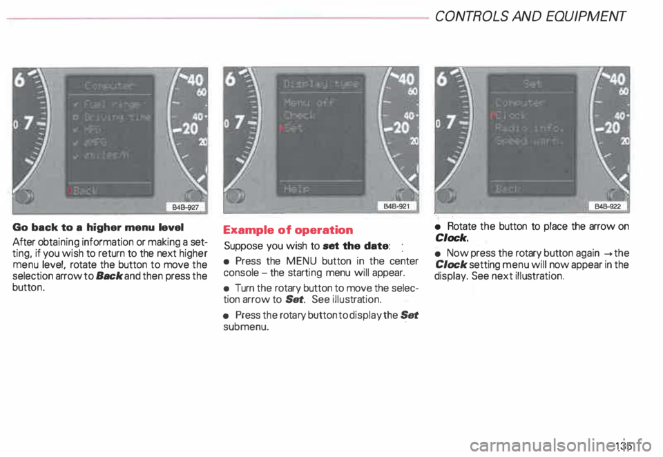
Go
back to a higher menu level
After obtaining information or making a set
ting, if you wish to return to the next higher
menu level, rotate the button to move the
selection arrow to Back and then press the
butt on. Example
of operation
Suppose you wish to set the date:
• Press the MENU button in the center
console -the starti ng menu will appear.
• Turn the rotary button to move the selec
tion arrow to Set. See illustra tion.
• Press the rota ry button to display the Set
submenu. · CONT
ROLS AND EQUIPMENT
• Rotate the button to place the arrow on
Clock.
• Now press the rotary button again __.the
Clock setting menu will now appear in the
display. See next illustra tion.
135