2000 AUDI ALLROAD instrument cluster
[x] Cancel search: instrument clusterPage 157 of 306
CONTROLS
AND EQUIPMENT---------------------
Turn signals, headlight dimmer switch lever
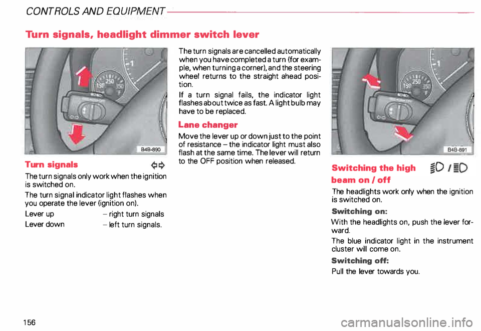
Turn signals
The turn signals only work when the ignition
is switched on.
The turn signal indicator light flashes when
you operate the lever (ignition on).
Lever up
Lever down
15 6 -
right turn signals
- left turn signals. The
turn signals are cancelled automatically
when you have completed a turn (for exam
ple, when turning a corner), and the steering
wheel returns to the straight ahead posi
tion.
If a turn signal fails, the indicator light
flashes about twice as fast. A light bulb may
have to be replaced.
Lane changer
Move the lever up or down just to the point
of resista nce-the ind icator light must also
flash at the same time. The lever will return
to the OFF position when released.
Switching the high
beam on/off
The headlights work only when the ignition
is switched on.
Swi tching on:
With the headlights on, push the lever for
ward.
The blue indicator light in the instrument
cluster will come on.
Switching off:
Pull the lever towards you.
Page 203 of 306
VE
HICL E OPER ATION------------------------
Functioning of Anti-Lock Brake
System (ABS)
The ABS contributes effectively to vehicle
control since it prevents the wheels from
locking when the brakes are applied. This
means that the vehicle remains steerable
and is less likely to skid.
Nota
Yo u don't have to "pump" the brake.
Just hold the brake pedal down.
However, do not expect that the ABS short
ens braking distance under all circum
stances. When driving on gravel or on newly
fallen snow on top of icy surfaces, braking
distance may be even longer , therefore, un
der these circumstances, it is especially im
portant that you drive slowly and with great
care.
202 How the
ABS system works
An automatic check is made when a speed
of about 4 mph (6 km/h) is reached.
When this happens a pumping noise can be
heard.
If an individual wheel begins to rotate too
slowly in relation to vehicle speed and tends
to lock, the ABS automatically reduces
brake pressure to prevent that wheel from
locking.
This automatic adjustment process
will cause a slight vibration of the
brake pedal and soma noises to alert
you that vehicle speed must be
adapted to existing road and traffic
conditions. Enhanced
ABS function {Offroad
Mode)
To improve braking on loose terrain (for ex
ample: gravel, scree, mud, slush, snow),
turn off the ESP (see page 205), which will
switch the ABS to a special mode designed
for off-road requirements.
In this mode, the ABS control system is
changed to allow a "wedge" of loose rock
or soil to form in the front of the wheels.
This improves braking performance.
The ESP indicator light in the instrument
cluster will come on when you have
switched to this special ABS mode (see
page 124).
This special ABS mode will remain active up
to about 40 mph (60 km/h). ABS operation
is not affected at speeds over 40 mph
(60 km/h).
To turn his special ABS mode off, press the
ESP button (To activate ESP, see page 152).
The ABS off-road mode will also be deacti
vated when vou turn off the engine.
Page 211 of 306
VEHICLE OPER
ATION-----------------------
Driving Instructions
To obtain the best possible handling of ve
hicle and trailer , please note the following:
• A "balanced" rig is easier to operate and
control. This means that the tow vehicle
should be loaded to the extent possible and
permissible while keeping the trailer as light
as possible under the circumstances.
Whenever possible, transfer some cargo to
the luggage compartment of the tow ve
hicle while observing tongue load require
ments and vehicle loading considerations.
• The higher the speed, the more difficult
it becomes for the driver to control the rig.
Do not drive at the maximum per
missible speed. Reduce your speed even
more under unfavorable load, weather or
wind conditions - particularly when going
dow nhill.
210 Be
especially careful when passing other
vehicles.
Reduce vehicle speed immediately if the
trailer shows the slightest sign of swaying.
Do not try to stop the sway ing by accel erat
ing.
Observe speed limits. In some areas
speeds for vehicles towing trailers are low
er than for regular vehicles.
• Always apply brakes early.
When driving downhill, shift into lower gear
to use the engine braking effect to slow
down the vehicle. Use of the brakes alone
can cause them to overheat and fail. •
The coolant temperatura gauge
must be observed carefully. H the
needle nears the upper end of the
scale, reduce speed immediately
and/or switch off the air condi
tioner.
If the coolant temperature warning
light in the instrument cluster starts
flashing in red, pull off the road,
stop and let the engine idle for about
2 minutes to prevent a heat build-up.
Page 236 of 306
Engine
oil consumption
The rate of the oil consumption depends on
the quality and viscosity of oil, the speed at
which the engine is operated, the climate,
and road conditions as well as amount of
dilution and oxidation of the lubricant.
Because of these variables, no standard
rate of oil consumption can be established,
but drivers should expect higher oil con
sumption at high speeds and when the en
gine is new.
Therefore, we recommend that you check
the oil level at regular intervals (for example,
each time you are refuelling, or before going
on a long trip).
If the oil level should go below the minimal
level, the check engine oil level warn
ing light* in the instrument cluster will
come on. See page 144. You should check
the oil level using the oil dip stick as soon as
possible, and then top off the oil as neces
sary. Notes
• The engine in your vehicle de
pends on oil to lubricate and cool all
of its moving parts. Therefore the
engine oil should be checked regu
larly and kept at the required level.
• Lack of sufficient engine oil may
lead to severe engine damage.
• The oil pressure warning light is
not an oil level indicator.
A Always
heed all WAR NINGS
� on page 232.
Checking the engine oil level
The best time to check the engine oil level
is when the oil is warm.
To get a true reading, the vehicle must be on
level ground.
A Always heed all WAR NINGS
� on page 232.
• After turning off the engine, wait a few
minu tes for the oil to return to the oil pan. VE
HICLE CARE
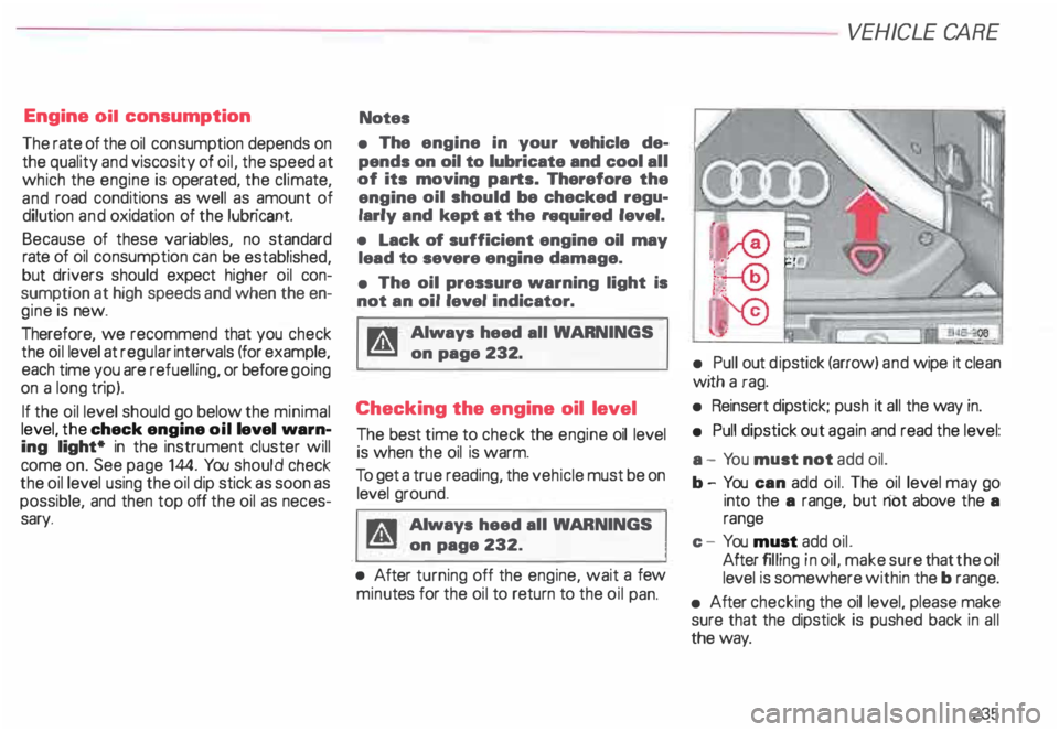
• Pull out dipstick (arrow) and wipe it clean
with a rag.
• Reinsert dipstick; push it all the way in.
• Pull dipstick out again and read the level:
a - Yo u must not add oil.
b- You can add oil. The oil level may go
into the a range, but riot above the a
range
c - You must add oil.
After filling in oil, make sure that the oil
level is somewhere within the b range.
• After checking the oil level, please make
sure that the dipstick is pushed back in all
the way.
235
Page 269 of 306
DO-IT-Y
OURSELF SERVICE----------------------
Step 1 ·"7
r.-&
.--· t I . ... ,.. . . . --------� .... ... . . ...
-
' . .. . ...
.. - - . .
J
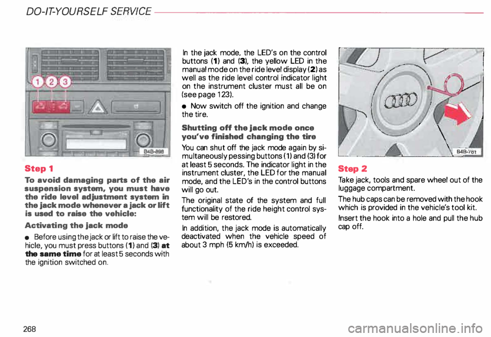
To avoid damaging parts of the air
suspension system. you must have
the ride level adjustment system in
the jack mode whenever a jack or lift
is used to raise the vehicle:
Activati ng the jack mode
• Before using the jack or lift to raise the ve
hicle, you must press buttons (1) and (3) at
the same time for at least 5 seconds with
the ignition switched on.
268 In
the jack mode. the LED's on the control
buttons (1) and (3), the yellow LED in the
manual mode on the ride level display (2) as
well as the ride level control indicator light
on the instrument cluster must all be on
(see page 123).
• Now switch off the ignition and change
the tire.
Shutting off the jack mode once
you've finished changing the tire
Yo u can shut off the jack mode again by si
mu ltaneously pessing buttons (1) and (3) for
at least 5 seconds. The indicator light in the
instrument cluster, the LED for the manual
mode, and the LED's in the control buttons
will go out.
The original state of the system and full
functionality of the ride height control sys
tem will be restored.
In addition, the jack mode is automatically
deactivated when the vehicle speed of
about 3 mph (5 km/h) is exceeded. Step
2
Ta ke jack, tools and spare wheel out of the
luggage compartment.
The hub caps can be removed with the hook
which is provided in the vehicl e's tool kit.
Insert the hook into a hole and pull the hub
cap off.
Page 276 of 306

Fuse
arrangement
No. 1 - Heated washer jets !
B45-087C I
A 11
- .. 5
2 - Turn signals . . . . . . . . .
. 10
3 - Headlight washer (relay)
illum ination for glove compartment,
climate control, Automatic
Tr ansmission, instrument cluster ... 5
4 - License plate light . . . 5
l) Amps No.
A1l
5 - Ins trument cluster, seat heating,
test connection for cruise control,
bulb monitor, Automatic
Tr ansmis sion display, switch lighting,
mirror switches and actuators,
airbag warning light, outside
temperature indicator, climate
control, solar roof, acoustic parking
assistance system, navigation
system, car telephone, 4 Level Air
Suspension ............ .. ...... 1 0
6 - Power locking system . . . . . . . . . 5
7 - Anti-lock brake system (ABS),
brake light switch . . . . . . . . . . . . 1 0
8 - Car telephone . . . . . . . . . . . . . . .
. 5
9 - Heated mirrors . . . . . . . . . . . . . . 1 0
1 0- Automatic headlight adjustment
. 5
11 -Cruise control
(Automatic Transmission) . . .
1 0
12- On Board Diagnostic system .... _ 10
13 -Brake lights . . . . . . 1 0 DO-IT-YOURSELF
SERVICE
No. 14 -Interior lights, reading lights,
anti-theft alarm system,
vanity mirror, seat memory ....... 10
15 -Instrument cluster, climate control,
mirror and seat mem ory, .
navigation system . . . . . . . . . . . . . . 1 0
16- Electronic Stability Programm ..... 5
17 -Navigation system, 4 Level Air
Suspension, automatic headlight
adjustment .............. ...... 10
18-Hig h-beam, right ......... ....... 10
19 -H igh-beam, left . . . . . . . . . . . . .. 1 0
20 � Low beam, right, headlight
adjustment . . . . . . . . . . . . . . . • . .
15
21 -Low beam, left, headlight
adjustment . . . . . . . . . . . . . . . .. 15
22 -Side marker and tail light, right . 5
23 -Side marker and tail light, left . . . . . 5
24 -Wiper and washer system . . 25
25 -Blower for heating (climate
control), solar roof 30
275
Page 285 of 306
DO-IT-YOURSELF
SERVICE----------------------
Jack
mode
Activat ing
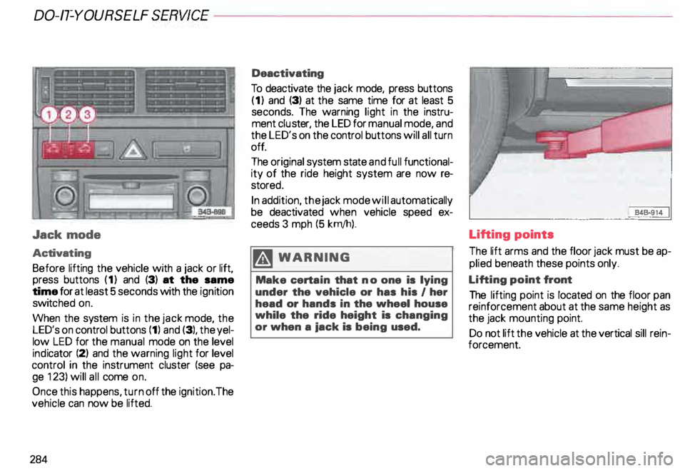
Before lifting the vehicle with a jack or lift,
press buttons (1) and (3) at the same
time for at least 5 seconds with the ignition
switc hed on.
When the system is in the jack mode, the
LED's on control buttons (1) and (3), the yel
low LED for the manual mode on the level
ind icator (2) and the warning light for level
control in the instrument cluster (see pa
ge 123) will all come on.
Once this happens, turn off the ignition. The
vehicle can now be lifted.
284 Deactivating
To deactivate the jack mode, press buttons
(1) and (3) at the same time for at least 5
seconds. The warning light in the instru
ment cluster, the LED for manual mode, and
the LED's on the control buttons will all turn
off.
The original system state and full functional
ity of the ride height system are now re
store d.
In addition, the jack mode will automatically
be deactivated when vehicle speed ex
ceeds 3 mph (5 krn/h).
.� WARNING
Make certain that no one is lying
under the vehicle or has his I her
head or hands in the wheel house
while the ride height is changing
or when a iack is being used. Lifting points
The
lift arms and the floor jack must be ap
plied beneath these points only.
Lifting point front
The lifting point is located on the floor pan
reinforcement about at the same height as
the jack mounting point.
Do not lift the vehicle at the vertical sill rein
forcement.
Page 300 of 306

- Capacities
. . . • . . . . . . . . • . . . 287
-C oolant . . . . . . . .
238
-W indshield washer tank . . . . 250
Fog lights .. .. .. .. .
. 149
Folding master key _ . . . . . . • . . 56
Four- Wheel Drive . . . . . • • . . 207
Front airbags .
. . . • • • . . . 25
Front axle load . . . • • . • • • . 289
Front fog lights .... ... .... .. .. 149
Front seats . . . . . . . . . . . . . . . . . . . . 76
Fuel -Tank capacity . . . . . . . . . . 222
Fuel economy . . . . . . . . . • . 19
5
Fuel gauge . . . . • • . . . .
119
Fuel supply . . . . . . . . . . . . . • . . . . . 225
Fuel tank . . . . . • . . . . . . . . 222
- Capacity
. • . • • . . • . . • • • . . 287
Fuses . . . •
... .•.. .• • .. . .. 274
G
Garage door opener ...• , • . . . . 173
Gas discharge lamps . . .
277
Gasoline additives . . . . .
227
Gauges and instruments
- Coolant temperature 118 -
Engine oil temperature
-F uel ........ . ..
117
.. 119
- Odometer . . . . . • . . • . . • . . . 11 9
- Speedometer . • . . . . . . . . . . 119
-T achome ter .. _. _...... ... 117
General illustration .
. . . . 8
Gen erator ....... ..... .
Glove box light ... .
Glo ve compartment . . . .
Ground clearance ... . _ .. 12
0, 127
17 8
17 8
153
Gross axle weight rating ...... . 289
289
Gross vehicle weight rating .... .
H
Head airbags . • . • . . • • • .•. . . 39
Head restraints . . . . • . . . . . 75
Headlight adjustment . . • . • • .
148
Headlight dimmer .....• , • . . . .
156
Headlight flasher . . . . . . . . . . . • . . 157
Headlights -Cleaning . .
214
Heated seats . . . . . . . . .
150
Heated steering wheel . 150
Heating . . . . . . . . . . . . . . 162
High beam . . . . . . . . . . . • . . . . . . 12
5 ALP
HABETIC AL INDE X
High voltage label
. . . . . • • . • 291
Hood release . . .
231
Hooks . . . . . . . . . • • • • • . .
.. 89
Horn . . . . . . . . . . . • • • . _ .. . .. .. . . . 8
Hydropla ning . . . . 195, 207
I
Identification label ..
291
Identification number ....... ... 290
Ign ition .................. ... 113
Ignition key safety interlock ..... 104
Immobilize r............. 57,
124
Increasing size of luggage
compartment ..... .
Ind icator lights ...... .
Infant seats .......... .
Inside day-night mirror
Installing a radio ..... .
Installing a roof rack ..
Installing wiper blades
Instru ment cluster .... ....
88
10, 122
. 45
. 72
277
191
. . .. -... 251
. . 116
Ins trument illumination . 14 9
Instrument panel . . . . .
. . . 8
Interior lights . . . . . . . . . . . . . . . 171