Page 1 of 4592

AC2810
AC0LG±02
AC2811
N11084
Wrong Okey
HI LO HILO
± AIR CONDITIONINGAIR CONDITIONING SYSTEM
AC±1
2483 Author�: Date�:
AIR CONDITIONING SYSTEM
PRECAUTION
1. DO NOT HANDLE REFRIGERANT IN AN ENCLOSED
AREA OR WEAR EYE PROTECTION
2. ALWAYS WEAR EYE PROTECTION
3. BE CAREFUL NOT TO GET LIQUID REFRIGERANT IN
YOUR EYES OR ON YOUR SKIN
If liquid refrigerant gets in your eyes or on your skin.
(a) Wash the area with lots of cool water.
CAUTION:
Do not rub your eyes or skin.
(b) Apply clean petroleum jelly to the skin.
(c) Go immediately to a physician or hospital for professional
treatment.
4. NEVER HEAT CONTAINER OR EXPOSE IT TO NAKED
FLAME
5. BE CAREFUL NOT TO DROP CONTAINER AND NOT
TO APPLY PHYSICAL SHOCKS TO IT
6. DO NOT OPERATE COMPRESSOR WITHOUT
ENOUGH REFRIGERANT IN REFRIGERATION SYS-
TEM
If there is not enough refrigerant in the refrigerant system oil lu-
brication will be insufficient and compressor burnout may occur,
so that care to avoid this, necessary care should be taken.
7. DO NOT OPEN PRESSURE MANIFOLD VALVE WHILE
COMPRESSOR IS OPERATE
If the high pressure valve is opened, refrigerant flows in the re-
verse direction and could cause the charging cylinder to rup-
ture, so open and close the only low pressure valve.
8. BE CAREFUL NOT TO OVERCHARGE SYSTEM WITH
REFRIGERANT
If refrigerant is overcharged, it causes problems such as insuffi-
cient cooling, poor fuel economy, engine overheating etc.
Page 3 of 4592

AC0LI±02
N20242
Sight Glass
± AIR CONDITIONINGAIR CONDITIONING SYSTEM
AC±3
2485 Author�: Date�:
ON±VEHICLE INSPECTION
1. INSPECT REFRIGERANT VOLUME
Observe the sight glass on the liquid tube.
Test conditions:
�Running engine at 1,500 rpm
�Blower speed control switch at ºHIº position
�A/C switch ON
�Temperature control dial at ºCOOLº position
�Fully open the doors
ItemSymptomAmount of refrigerantRemedy
1Bubbles present in sight glassInsufficient*
(1) Check for gas leakage with gas leak de-
tector and repair if necessary
(2) Add refrigerant until bubbles disappear
2No bubbles present in sight glassNone, sufficient or too muchRefer item 3 and 4
3No temperature difference between com-
pressor inlet and outletEmpty or nearly empty
(1) Check for gas leakage with gas leak de-
tector and repair if necessary
(2) Add refrigerant until bubbles disappear
4Temperature between compressor inlet and
outlet is noticeably differentCorrect or too muchRefer to items 5 and 6
5Immediately after air conditioning is turned
off, refrigerant in sight glass stays clearToo much
(1) Discharge refrigerant
(2) Evacuate air and charge proper amount
or purified refrigerant
6When air conditioning is turned off, refriger-
ant foams and then stays clearCorrect±
*: Bubbles in the sight glass with ambient temperatures higher than usual can be considered normal if cooling
is sufficient.
Page 7 of 4592

I01390
Condition: Insufficient cooling
I01392
Condition: Insufficient cooling
NOTE : These gauge indica-
tions are shown when the
refrigeration system has
been opened and the refrig-
erant charged without vacu-
um purging.
± AIR CONDITIONINGAIR CONDITIONING SYSTEM
AC±7
2489 Author�: Date�:
(6) Refrigerant overcharged or insufficient cooling of
condenser
Symptom seen in
refrigeration systemProbable causeDiagnosisRemedy
� Pressure too high on both low
and high pressure sides
� No air bubbles seen through the
sight glass even when the engine
rpm is lowered� Unable to develop sufficient per-
formance due to excessive refrig-
eration system
� Insufficient cooling of condenser� Excessive refrigerant in
cycle " refrigerant over charged
� Condenser cooling " condenser
fins clogged of condenser fan
faulty
(1) Clean condenser
(2) Check condenser fan motor
operation
(3) If (1) and (2) are in normal
state, check amount of refrigerant
Charge proper amount of refriger-
ant
(7) Air present in refrigeration system
Symptom seen in
refrigeration systemProbable causeDiagnosisRemedy
� Pressure too high on both low
and high pressure sides
� The low pressure piping hot to
touch
� Bubbles seen in sight glass
Air entered in refrigeration system
� Air present in refrigeration sys-
tem
� Insufficient vacuum purging
(1) Check compressor oil to see if
it is dirty or insufficient
(2) Evacuate air and charge new
refrigerant
Page 8 of 4592
I01450
Condition: Insufficient cooling
I01393
Condition : Does not cool AC±8
± AIR CONDITIONINGAIR CONDITIONING SYSTEM
2490 Author�: Date�:
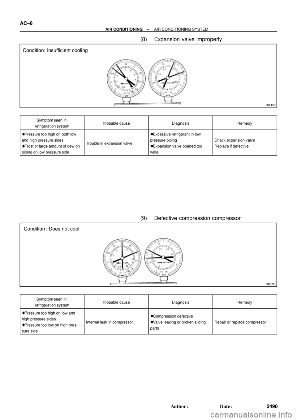
(8) Expansion valve improperly
Symptom seen in
refrigeration systemProbable causeDiagnosisRemedy
� Pressure too high on both low
and high pressure sides
� Frost or large amount of dew on
piping on low pressure side
Trouble in expansion valve
� Excessive refrigerant in low
pressure piping
� Expansion valve opened too
wide
Check expansion valve
Replace if defective
(9) Defective compression compressor
Symptom seen in
refrigeration systemProbable causeDiagnosisRemedy
� Pressure too high on low and
high pressure sides
� Pressure too low on high pres-
sure side
Internal leak in compressor
� Compression defective
� Valve leaking or broken sliding
parts
Repair or replace compressor
Page 10 of 4592
AC0LJ±03
N13795
Quick Disconnect
Adapter
Charging
Service ValveHose
N13794
Vacuum Pump
Vacuum Pump Adapter
N13791
Low Pressure
Service Valve
Vacuum Pump Adapter High Pressure
Service ValveManifold
Gauge
Set
AC±10
± AIR CONDITIONINGAIR CONDITIONING SYSTEM
2492 Author�: Date�:
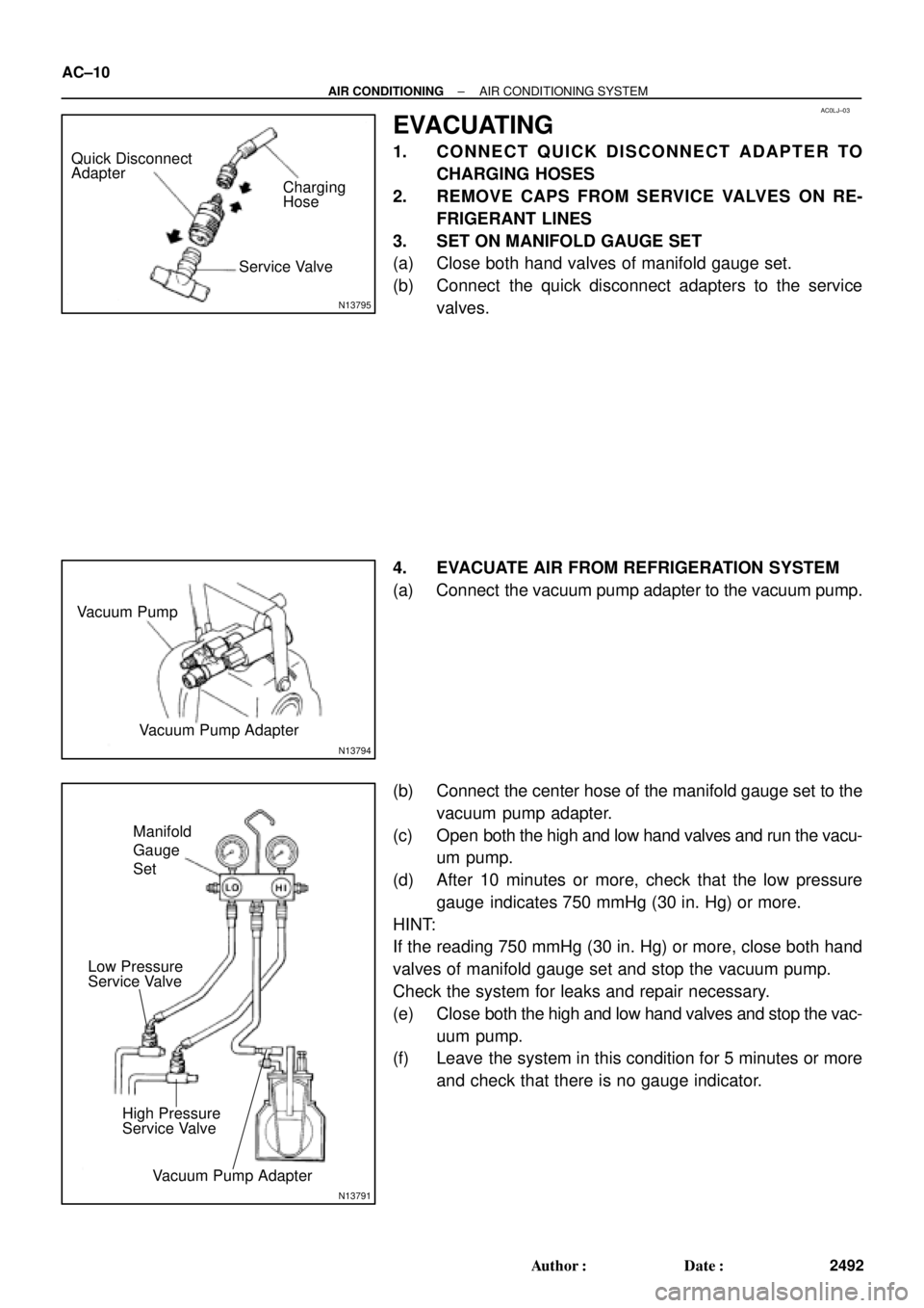
EVACUATING
1. CONNECT QUICK DISCONNECT ADAPTER TO
CHARGING HOSES
2. REMOVE CAPS FROM SERVICE VALVES ON RE-
FRIGERANT LINES
3. SET ON MANIFOLD GAUGE SET
(a) Close both hand valves of manifold gauge set.
(b) Connect the quick disconnect adapters to the service
valves.
4. EVACUATE AIR FROM REFRIGERATION SYSTEM
(a) Connect the vacuum pump adapter to the vacuum pump.
(b) Connect the center hose of the manifold gauge set to the
vacuum pump adapter.
(c) Open both the high and low hand valves and run the vacu-
um pump.
(d) After 10 minutes or more, check that the low pressure
gauge indicates 750 mmHg (30 in. Hg) or more.
HINT:
If the reading 750 mmHg (30 in. Hg) or more, close both hand
valves of manifold gauge set and stop the vacuum pump.
Check the system for leaks and repair necessary.
(e) Close both the high and low hand valves and stop the vac-
uum pump.
(f) Leave the system in this condition for 5 minutes or more
and check that there is no gauge indicator.
Page 11 of 4592
AC21S±01
N13793
Charging Cylinder High Pressure
Service Valve Low Pressure
Service ValvePush
Air
N13792
Gas Leak
Detector
± AIR CONDITIONINGAIR CONDITIONING SYSTEM
AC±11
2493 Author�: Date�:
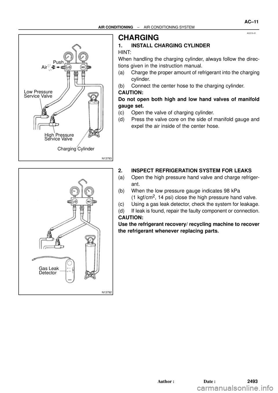
CHARGING
1. INSTALL CHARGING CYLINDER
HINT:
When handling the charging cylinder, always follow the direc-
tions given in the instruction manual.
(a) Charge the proper amount of refrigerant into the charging
cylinder.
(b) Connect the center hose to the charging cylinder.
CAUTION:
Do not open both high and low hand valves of manifold
gauge set.
(c) Open the valve of charging cylinder.
(d) Press the valve core on the side of manifold gauge and
expel the air inside of the center hose.
2. INSPECT REFRIGERATION SYSTEM FOR LEAKS
(a) Open the high pressure hand valve and charge refriger-
ant.
(b) When the low pressure gauge indicates 98 kPa
(1 kgf/cm
2, 14 psi) close the high pressure hand valve.
(c) Using a gas leak detector, check the system for leakage.
(d) If leak is found, repair the faulty component or connection.
CAUTION:
Use the refrigerant recovery/ recycling machine to recover
the refrigerant whenever replacing parts.
Page 12 of 4592

N13790
Low Pressure
Service Valve
High Pressure
Service Valve
I07055
Properly
Charged
Insufficiently
Charged AC±12
± AIR CONDITIONINGAIR CONDITIONING SYSTEM
2494 Author�: Date�:
3. CHARGE REFRIGERANT INTO REFRIGERANT SYS-
TEM
If there is no leak after refrigerant leak check, charge the proper
amount of refrigerant into refrigeration system.
CAUTION:
�Never run the engine when charging the system
through the high pressure side.
�Do not open the low pressure hand valve when the
system is being charged with liquid refrigerant.
(a) Open the high pressure hand valve fully.
(b) Charge specified amount of refrigerant, then close the
high pressure hand valve.
HINT:
A fully charged system is indicated by the sight glass being free
of any bubbles.
(c) Charge partially refrigeration system with refrigerant.
(1) Set vehicle in these conditions:
�Running engine at 1,500 rpm
�Blower speed control set at ºHIº
�Temperature control set at ºMAX. COOLº
�Air inlet control set at ºRECIRCº
�Fully open doors (Sliding roof: closed)
(2) Open the low pressure hand valve.
CAUTION:
Do not open the high pressure hand valve.
(d) Charge refrigerant until bubbles disappear and check the
pressure on the gauge through the sight glass.
Page 23 of 4592
AC0LT±03
± AIR CONDITIONINGREFRIGERANT LINE
AC±23
2505 Author�: Date�:
REPLACEMENT
1. DISCHARGE REFRIGERANT FROM REFRIGERATION SYSTEM
2. REPLACE FAULTY TUBE OR HOSE
NOTICE:
Cap the open fittings immediately to keep moisture or dirt out of the system.
3. TIGHTEN JOINT OF BOLT OR NUT TO SPECIFIED TORQUE
NOTICE:
Connections should not be torqued tighter than the specified torque.
Part tightenedN´mkgf´cmft´lbf
Receiver x Liquid tube5.45548 in.´lbf
Condenser x Discharge hose101007
Condenser x Liquid tube1414010
Compressor x Discharge hose101007
Compressor x Suction hose101007
Expansion valve x Evaporator5.45548 in.´lbf
Suction line (Piping joint)3233024
Suction line (Block joint)101007
4. EVACUATE AIR FROM REFRIGERATION SYSTEM AND CHARGE WITH REFRIGERANT
Specified amount : 800 ± 50g (28.22 ± 1.76 oz.)
5. INSPECT FOR LEAKAGE OF REFRIGERANT
Using a gas leak detector, check for leakage of refrigerant.
6. INSPECT AIR CONDITIONING OPERATION