RS01Y±22
± SUPPLEMENTAL RESTRAINT SYSTEMSRS AIRBAG
RS±1
2146 Author�: Date�:
SRS AIRBAG
PRECAUTION
NOTICE:
�The CAMRY is equipped with SRS, which comprises a driver airbag, front passenger airbag,
and side airbag. Failure to carry out service operations in the correct sequence could cause
the SRS to unexpectedly deploy during servicing, possibly leading to a serious accident. Fur-
ther, if a mistake is made in servicing the SRS, it is possible that the SRS may fail to operate
when required. Before performing servicing (including removal or installation of parts, inspec-
tion or replacement), be sure to read the following items carefully, then follow the correct proce-
dures described in the repair manual.
�Malfunction symptoms of the SRS are difficult to confirm, so the DTCs become the most impor-
tant source of information when troubleshooting. When troubleshooting the SRS, always in-
spect the DTCs before disconnecting the battery.
�Even in cases of a minor collision where the SRS does not deploy, the steering wheel pad, front
passenger airbag assembly, side airbag assembly (TMC made and TMMK made), airbag sensor
assembly, front airbag sensor and side airbag sensor assembly should be inspected.
(See page RS±16, RS±29, RS±41, RS±54, RS±60, RS±65 and RS±70)
�Never use SRS parts from another vehicle. When replacing parts, replace them with new parts.
�Never disassemble and repair the steering wheel pad, front passenger airbag assembly, side
airbag assembly, airbag sensor assembly, front airbag sensor or side airbag sensor assembly
in order to reuse it.
�If the steering wheel pad, front passenger airbag assembly, side airbag assembly, airbag sen-
sor assembly, front airbag sensor or side airbag sensor assembly has been dropped, or if there
are cracks, dents or other defects in the case, bracket or connector, replace them with new
ones.
�Use a volt/ohmmeter with high impedance (10 kW/V minimum) for troubleshooting the system's
electrical circuits.
�Information labels are attached to the periphery of the SRS components. Follow the instruc-
tions on the notices.
�After work on the SRS is completed, perform the SRS warning light check (See page DI±626).
�If the vehicle is equipped with a mobile communication system, refer to the precaution in the
IN section.
CAUTION:
�Work must be started 90 seconds after the ignition switch is turned to the ºLOCKº position and
the negative (±) terminal cable is disconnected from the battery.
(The SRS is equipped with a back±up power source so that if work is started within 90 seconds
from disconnecting the negative (±) terminal cable of the battery, the SRS may be deployed.)
�When the negative (±) terminal cable is disconnected from the battery, the memory of the clock
and audio system will be canceled. So before starting work, make a record of the contents mem-
orized in the audio memory system. When work is finished, reset the audio systems as they
were before and adjust the clock. To avoid erasing the memory in each memory system, never
use a back± up power supply from outside the vehicle.
�Before repairs, remove the airbag sensor if shocks are likely to be applied to the sensor during
repairs.
�Do not expose the steering wheel pad, front passenger airbag assembly, side airbag assembly,
airbag sensor assembly, front airbag sensor or side airbag sensor assembly directly to hot air
or flames.
H02309
H02266
H08235
H03284
± SUPPLEMENTAL RESTRAINT SYSTEMSRS AIRBAG
RS±3
2148 Author�: Date�:
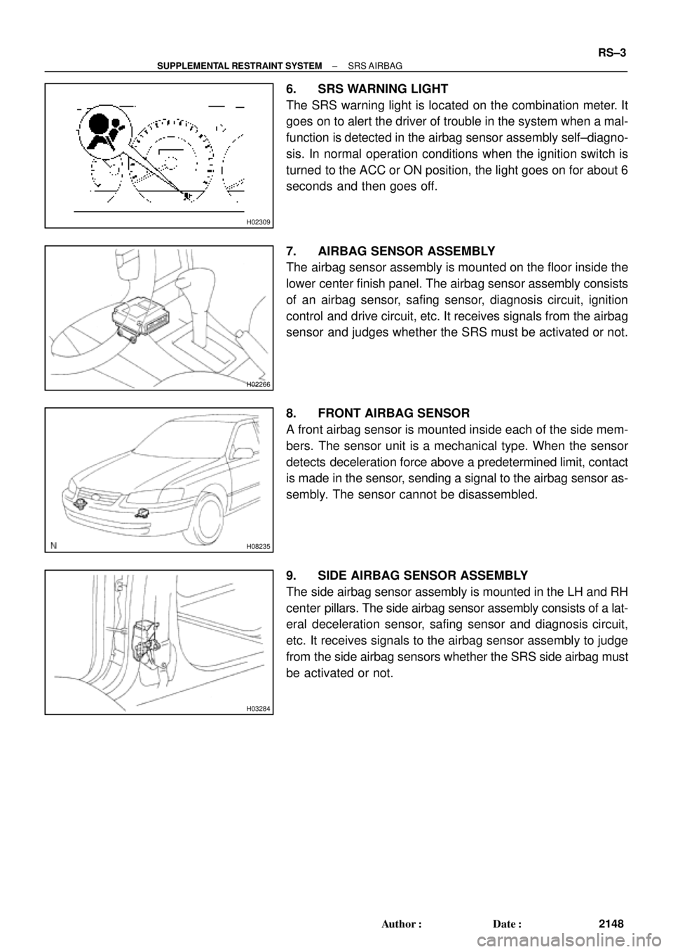
6. SRS WARNING LIGHT
The SRS warning light is located on the combination meter. It
goes on to alert the driver of trouble in the system when a mal-
function is detected in the airbag sensor assembly self±diagno-
sis. In normal operation conditions when the ignition switch is
turned to the ACC or ON position, the light goes on for about 6
seconds and then goes off.
7. AIRBAG SENSOR ASSEMBLY
The airbag sensor assembly is mounted on the floor inside the
lower center finish panel. The airbag sensor assembly consists
of an airbag sensor, safing sensor, diagnosis circuit, ignition
control and drive circuit, etc. It receives signals from the airbag
sensor and judges whether the SRS must be activated or not.
8. FRONT AIRBAG SENSOR
A front airbag sensor is mounted inside each of the side mem-
bers. The sensor unit is a mechanical type. When the sensor
detects deceleration force above a predetermined limit, contact
is made in the sensor, sending a signal to the airbag sensor as-
sembly. The sensor cannot be disassembled.
9. SIDE AIRBAG SENSOR ASSEMBLY
The side airbag sensor assembly is mounted in the LH and RH
center pillars. The side airbag sensor assembly consists of a lat-
eral deceleration sensor, safing sensor and diagnosis circuit,
etc. It receives signals to the airbag sensor assembly to judge
from the side airbag sensors whether the SRS side airbag must
be activated or not.
AB0089
Secondary Lock
Primary LockLockLock
Primary Lock Incomplete
(Secondary Lock Prevented)Primary Lock Complete
(Secondary Lock Permitted)Twin±Lock Completed
Z14034
Fig.1
Fig.2Power Source
Safing
Sensor
Squibs
Deceleration
Sensor RS±8
± SUPPLEMENTAL RESTRAINT SYSTEMSRS AIRBAG
2153 Author�: Date�:
(4) Connector twin±lock mechanism
With this mechanism connectors (male and female
connectors) are locked by 2 locking devices to in-
crease the connection reliability. If the primary lock
is incomplete, ribs interfere and prevent the sec-
ondary lock.
(b) When the vehicle is involved in a frontal collision in the
hatched area (Fig. 1) and the shock is larger than the pre-
determined level, the SRS is activated automatically. A
safing sensor is designed to go on at a smaller decelera-
tion rate than the airbag sensor. As illustrated in Fig. 2,
ignition is caused when current flows to the squib, which
happens when a safing sensor and the deceleration sen-
sor go on simultaneously. When a deceleration force acts
on the sensors, 2 squibs in the driver airbag and front pas-
senger airbag ignite and generate gas. The gas discharg-
ing into the driver airbag and front passenger airbag rap-
idly increases the pressure inside the bags, breaking
open the steering wheel pad and instrument panel door.
Bag inflation then ends, and the bags deflate as the gas
is discharged through discharge holes at the bag's rear or
side.


Primary Lock Complete
(Secondary Lock Permitted)Twin±Lock Completed
Z14034
Fig.1
Fig.2Power Source
Safing")