Page 769 of 4592
N20219
Type A:
Type B and C:1
7
9
10
1
7
910
N20220
Type A:
Type B and C:1
7
9
10
1
7910 88
± BODY ELECTRICALCOMBINATION METER
BE±53
2273 Author�: Date�:
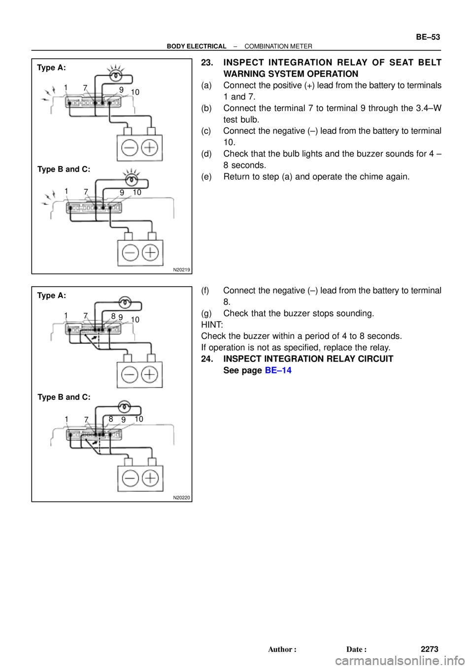
23. INSPECT INTEGRATION RELAY OF SEAT BELT
WARNING SYSTEM OPERATION
(a) Connect the positive (+) lead from the battery to terminals
1 and 7.
(b) Connect the terminal 7 to terminal 9 through the 3.4±W
test bulb.
(c) Connect the negative (±) lead from the battery to terminal
10.
(d) Check that the bulb lights and the buzzer sounds for 4 ±
8 seconds.
(e) Return to step (a) and operate the chime again.
(f) Connect the negative (±) lead from the battery to terminal
8.
(g) Check that the buzzer stops sounding.
HINT:
Check the buzzer within a period of 4 to 8 seconds.
If operation is not as specified, replace the relay.
24. INSPECT INTEGRATION RELAY CIRCUIT
See page BE±14
Page 916 of 4592

BO0MB±01
N20950
Instrument Panel ReinforcementNN
DD
No.2 Instrumental Panel Bracket
No.1 Instrumental Panel Bracket
No.2 Instrumental Panel Brace
QQH N
N
N
N
GG
NG
NOB
NN
Instrument Panel Brace Mount
No.1 Instrument
Panel BraceFront Pillar Garnish
Front Pillar
GarnishFront
Passenger
Airbag
Assembly
20 (200, 14)
No.2 Side Defroster Nozzle
Cowl Side Trim
Front Door Openin
g
Cover
Instrument Panel
C
Remote Control
Mirror Hole Base
Upper Column
CoverHazard Warning
Switch
Lower Finish
PlateGlove Compartment
Door Finish PlateFront Door
Inside Scuff Plate
FFF
FJ
Glove
Compartment
No.2 Lower
Panel A
A
Cluster Finish
Panel
Lower Column
Cover
Front Door
Opening
Cover
Cowl Side
TrimD
DD
D
D
F
AA
Lower Panel
InsertCoin
BoxCombination SwitchCombination
MeterRadio Assembly
Center Cluster
Finish Panel
A/C
Control Assembly
35 (360, 26)
Steering
Wheel
Pad Steering Wheel No.1 Lower
Panel
Front Door
Inside Scuff PlateFront Console
Box
Center Console
Upper PanelF
F
B
B
Rear Console
Box
N´m (kgf´cm, ft´lbf) : Specified torque BO±72
± BODYINSTRUMENT PANEL
2420 Author�: Date�:
INSTRUMENT PANEL
COMPONENTS
Page 920 of 4592
 Using a screwdriver, remove the glove compartment door
finish plate to")
N20988
N21023
7 Clips
N21024
6 Clips BO±76
± BODYINSTRUMENT PANEL
2424 Author�: Date�:
8. REMOVE GLOVE COMPARTMENT ASSEMBLY
(a) Using a screwdriver, remove the glove compartment door
finish plate to the glove compartment box inside.
NOTICE:
When handling the airbag connector, be careful not to dam-
age the airbag wire harness.
HINT:
Tape the screwdriver tip before use.
(b) Pull up and disconnect the airbag connector.
(c) Remove the 4 screws, bolt and glove compartment as-
sembly.
9. REMOVE CENTER CONSOLE UPPER PANEL
Using a screwdriver, remove the panel, then disconnect the
connector.
HINT:
Tape the screwdriver tip before use.
10. REMOVE REAR CONSOLE BOX
Remove the 2 bolts, 2 screws and the console box.
11. REMOVE CENTER CLUSTER FINISH PANEL
Using a screwdriver, remove the panel, then disconnect the
connector.
HINT:
Tape the screwdriver tip before using.
12. REMOVE FRONT CONSOLE BOX
Remove the 2 screws and the front console box.
13. REMOVE RADIO ASSEMBLY
14. REMOVE A/C CONTROL ASSEMBLY
(See page AC±82)
15. REMOVE HAZARD WARNING SWITCH
16. REMOVE CLUSTER FINISH PANEL
(a) Remove the 2 screws.
(b) Using a screwdriver, remove the panel.
HINT:
Tape the screwdriver tip before use.
17. REMOVE COMBINATION METER
18. REMOVE REMOTE CONTROL MIRROR HOLE BASE
Page 979 of 4592

BO0NL±01
H01352
BO±134
± BODYSEAT BELT PRETENSIONER
2482 Author�: Date�:
INSTALLATION
NOTICE:
Never use seat belt pretensioner from another vehicle.
When replace parts, replace them with new parts.
1. INSTALL FRONT SEAT OUTER BELT
(a) Install the front seat belt parts by following the reverse or-
der of removal and torque the following bolts.
(1) Front seat outer belt retractor
Torque: 7.8 N´m (80 kgf´cm, 69 in.´lbf)
(2) Seat belt shoulder anchor
Torque: 42 N´m (430 kgf´cm, 31 ft´lbf)
(3) Seat belt floor anchor
Torque: 42 N´m (430 kgf´cm, 31 ft´lbf)
NOTICE:
�Make sure that the front seat outer belt is installed
with the specified torque.
�If the front seat outer belt has been dropped, or there
are cracks, dents or other defects in the case or con-
nector, replace the front seat outer belt with a new
one.
�When installing the front seat outer belt, take care that
the wiring does not interfere with other parts and is
not pinched between other parts.
(b) Connect the pretensioner connector as shown in the il-
lustration.
(c) w/ Seat Belt Warning:
Connect the retractor switch connector.
2. INSTALL THESE PARTS:
(a) Center pillar lower garnish
(b) Front door scuff plate
Page 980 of 4592

BE16T±01
± BODY ELECTRICALTROUBLESHOOTING
BE±1
533 Author�: Date�:
TROUBLESHOOTING
PROBLEM SYMPTOMS TABLE
COMBINATION METER
METER, GAUGES AND ILLUMINATION:
SymptomSuspect AreaSee page
Tachometer, Fuel Gauge and Engine Coolant Temperature Gauge
do not operate.1. GAUGE Fuse (I/P J/B No.1)
2. Meter Circuit Plate
3. Wire Harness±
BE±4
±
Fuel Gauge does not operate or abnormal operation.
1. Fuel Receiver Gauge
2. Fuel Temperature Sensor (For Delivery Pipe)
3. Fuel Temperature Sensor (For Fuel Tank)
4. Fuel Pressure Sensor (For Delivery Pipe)
5. Fuel Pressure Sensor (For Fuel Pipe)
6. ECM
7. Meter Circuit Plate
8. Wire HarnessBE±5
SF±36
SF±40
SF±42
SF±45
±
BE±4
±
Engine Coolant Temperature Gauge does not operate or abnormal
operation
1. Engine Coolant Temperature Receiver Gauge
2. Engine Coolant Temperature Sender Gauge
3. Meter Circuit Plate
4. Wire HarnessBE±5
BE±5
BE±4
±
All illumination lights do not light up.
1. TAIL Fuse (I/P J/B No.1)
2. Light Control Rheostat
3. Wire Harness±
BE±54*
±
Only one illumination light does not light up.1. Bulb
2. Wire Harness±
±
COMBINATION METER
WARNING LIGHTS:
SymptomSuspect AreaSee page
Warning lights do not light up. (Except Discharge, Open Door and
SRS)1. GAUGE Fuse (I/P J/B No.1)
2. Meter Circuit Plate
3. Wire Harness±
BE±4
±
Low Oil Pressure warning light does not light up.
1. Bulb
2. Low Oil Pressure Warning Switch
3. Meter Circuit Plate
4. Wire Harness±
BE±5
BE±4
±
Fuel Level warning light does not light up.
1. Bulb
2. Fuel Temperature Sensor (For Delivery Pipe)
3. Fuel Temperature Sensor (For Fuel Tank)
4. Fuel Pressure Sensor (For Delivery Pipe)
5. Fuel Pressure Sensor (For Fuel Pipe)
6. ECM
7. Meter Circuit Plate
8. Wire Harness±
SF±36
SF±40
SF±42
SF±45
±
BE±4
±
*: See Pub. No. RM654U
Page 981 of 4592
BE0AI±04
I08447
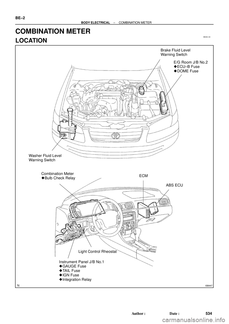
Brake Fluid Level
Warning Switch
E/G Room J/B No.2
� ECU±B Fuse
� DOME Fuse
Washer Fluid Level
Warning Switch
Combination Meter
� Bulb Check RelayECM
ABS ECU
Light Control Rheostat
Instrument Panel J/B No.1
� GAUGE Fuse
� TAIL Fuse
� IGN Fuse
� Integration Relay
BE±2
± BODY ELECTRICALCOMBINATION METER
534 Author�: Date�:
COMBINATION METER
LOCATION
Page 982 of 4592
I08448
PKB Switch
Seat Belt Buckle SwitchDoor Courtesy Switch
Door Courtesy Switch
Light Failure Sensor
Low Oil Pressure Warning Switch
Engine Coolant Temperature
Sender Gauge
Park/Neutral Position Switch
± BODY ELECTRICALCOMBINATION METER
BE±3
535 Author�: Date�:
Page 983 of 4592

BE0AJ±04
Z18937
Connector ºAº Connector ºBº Connector ºCº
Connector ºAº
Connector ºBº
Connector ºCº
J±13±1±A J±16±1 J±13±1
1 2 3 4 5 6 7 8 9 10 11 12 1314 15 16 1 234 56 78 910111213 1 23456 78910111213
C7
C5
A2 B3
A1
C8
B15
C6
B6
A4
C4
B5
C10 B14
A13
B2
C1
B1
C9
A6
A11
A7
A10
A8
A9
C13
B8
B11
B12A5
C11
B4
B16 C2
A12
A3
B7
C3
C12
B9
B10
B13 F
E
T
S
ODOMETER
Fuel Level Warning
Seat Belt Warning
ABS Warning
Low Oil Pressure Warning
Cruise Control Indicator
Malfunction Indicator
O/D OFF Indicator
Light Failure Warning
Brake Warning
SLIP Indicator
TRAC Indicator
Washer Level Warning
Discharge Warning
Right Turn Indicator
Left Turn Indicator
Security Indicator
L
2
D
N
R
P
Illumination
Hi±Beam Indicator
Open Door Warning
SRS Warning
: Fuel Gauge
: Engine Coolant Temperature Sender Gauge
: Tachometer
: Speedometer
No.
A
B
C1
2
3
4
5
6
7 8
9
10
11
12 13
14
15
16
2 3
4
5
6
7 8
9
10
11 12
131
2
3
4 5
6
7
8
9
10
11
12
13
F
E
T
SEngine coolant temperature sender gauge
Ground
Light failure sensor
Integration relay
Traction ECU
Park/neutral position switch (A/T)
O/D OFF switch (A/T)
IGN fuse
Turn signal switch
ST relay
ECM
Generator
Oil pressure switch
ECM
Parking brake switch and brake fluid level warning switch
Headlight dimmer switch
Headlight dimmer switch
Door courtesy switch
DOME fuse
ECU±B fuse
Airbag sensor assembly
ECM
No.1 Vehicle speed sensor Ground
Turn signal switch ECM
Traction ECU
ABS ECU
Ground No.1 Vehicle speed sensor
GAUGE fuse
Igniter
Security ECU
Cruise control ECU
Washer fluid level warning switch
Light control rheostat
TAIL fuse Park/neutral position switch (A/T) Park/neutral position switch (A/T) Park/neutral position switch (A/T) Park/neutral position switch (A/T)
Park/neutral position switch (A/T)Wire Harness Side
Bulb Check
Relay
N20107 N201081
BE±4
± BODY ELECTRICALCOMBINATION METER
CIRCUIT