Page 984 of 4592

BE16U±01
I12031
Ignition
Switch
Fuel
Gauge
BatteryECM
I12029
Ignition
SwitchFuel Gauge
BatteryWire Harness Side
N20212
A
B
C
I12030
BatteryWarning Light
Ignition
Switch
Wire Harness Side
± BODY ELECTRICALCOMBINATION METER
BE±5
INSPECTION
1. INSPECT FUEL RECEIVER GAUGE OPERATION
(a) Disconnect the connector from the ECM.
(b) Turn the ignition switch ON, check that the receiver gauge
needle indicates EMPTY.
(c) Connect terminals 2 on the wire harness side connector
through a 3.4±W test bulb.
(d) Turn the ignition switch ON, check that the bulb lights up
and the receiver gauge needle moves towards the full
side.
HINT:
Because of the silicon oil in the gauge, it will take a short time
for needle to stabilize.
If operation is not as specified, inspect the receiver gauge resis-
tance.
2. INSPECT FUEL RECEIVER GAUGE RESISTANCE
Measure the resistance between terminals.
Tester connectionResistance (W)
A ± BApprox. 270.1
A ± CApprox. 141.3
B ± CApprox. 128.8
If resistance value is not as specified, replace the receiver
gauge.
3. INSPECT FUEL SENDER GAUGE RESISTANCE
(See page SF±36)
4. INSPECT FUEL LEVEL WARNING LIGHT
(a) Disconnect the connector from the sender gauge.
(b) Connect terminals 8 on the wire harness side connector.
(c) Turn the ignition switch ON, check that the warning light
lights up.
If the warning light does not light up, test the bulb or inspect wire
harness.
5. INSPECT FUEL LEVEL WARNING SWITCH
(See page SF±40)
Page 986 of 4592

I07709
Slide
rheostat35.63 ±
0.1 W35.63 ±
0.1 W
Z14205
Warning Light
Ignition
Switch
Battery
1
N06640
± BODY ELECTRICALCOMBINATION METER
BE±7
8. INSPECT ENGINE COOLANT TEMPERATURE SEND-
ER GAUGE RESISTANCE
Connect the wire harness as shown in the illustration, and ad-
just the ammeter pointer to indicate º0º using the slide rheostat,
then read the rheostat indication.
Temperature °C (°F)Resistance (W)
50 (122.0)160 ± 240
120 (248.0)17.1 ± 21.2
If resistance value is not as specified, replace the engine cool-
ant temperature sender gauge.
9. INSPECT LOW OIL PRESSURE WARNING LIGHT
(a) Disconnect the connector from the warning switch and
ground terminal on the wire harness side connector.
(b) Turn the ignition switch ON and check that the warning
light lights up.
If the warning light does not light up, test the bulb.
10. INSPECT LOW OIL PRESSURE SWITCH
(a) Disconnect the connector from the switch.
(b) Check that continuity exists between terminal and ground
with the engine stopped.
(c) Check that no continuity exists between terminal and
ground with the engine running.
HINT:
Oil pressure should be over 24.5 kPa (0.25 kgf/cm
2, 3.55 psi).
If operation is not as specified, replace the switch.
Page 1025 of 4592
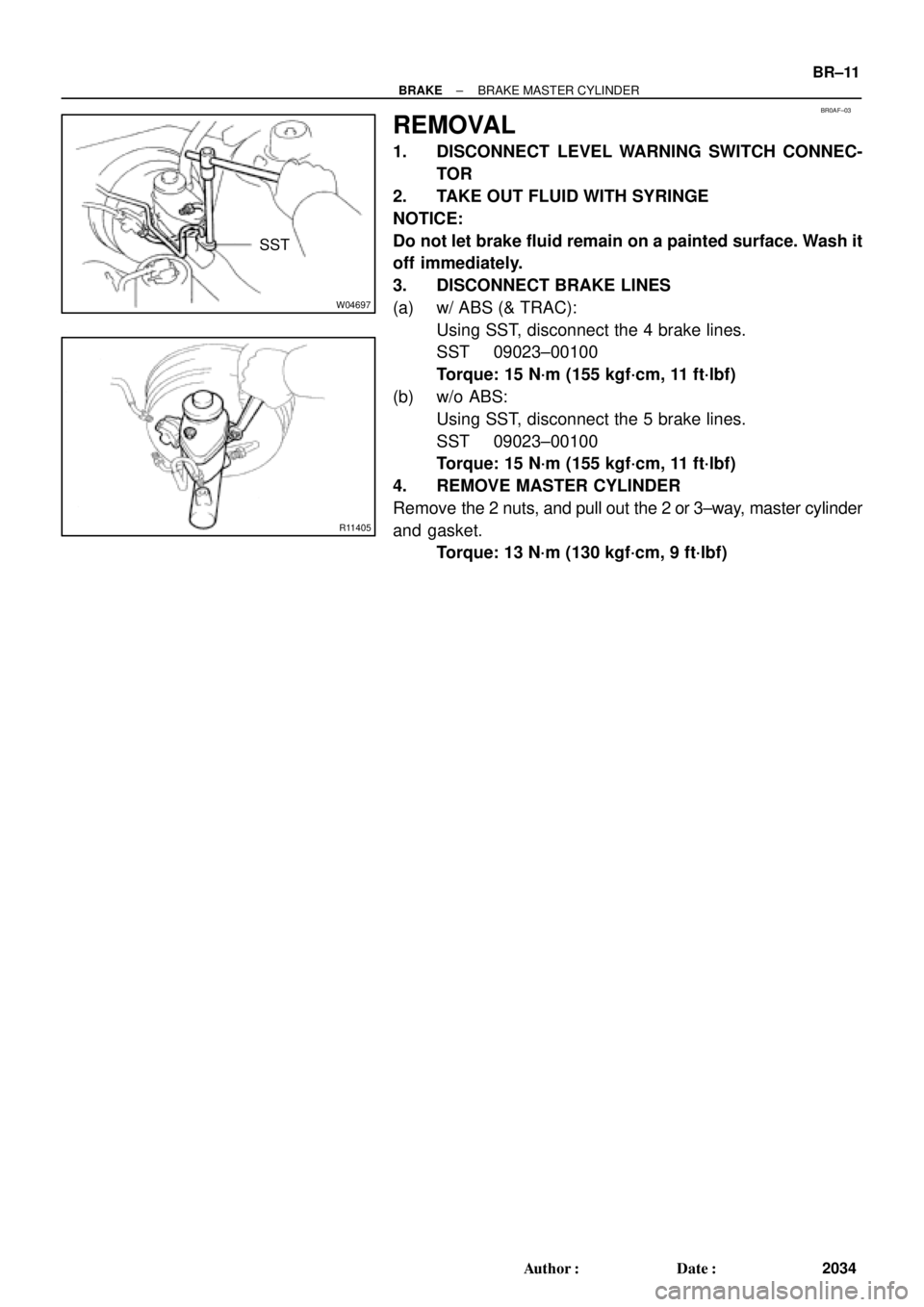
BR0AF±03
W04697
SST
R11405
± BRAKEBRAKE MASTER CYLINDER
BR±11
2034 Author�: Date�:
REMOVAL
1. DISCONNECT LEVEL WARNING SWITCH CONNEC-
TOR
2. TAKE OUT FLUID WITH SYRINGE
NOTICE:
Do not let brake fluid remain on a painted surface. Wash it
off immediately.
3. DISCONNECT BRAKE LINES
(a) w/ ABS (& TRAC):
Using SST, disconnect the 4 brake lines.
SST 09023±00100
Torque: 15 N´m (155 kgf´cm, 11 ft´lbf)
(b) w/o ABS:
Using SST, disconnect the 5 brake lines.
SST 09023±00100
Torque: 15 N´m (155 kgf´cm, 11 ft´lbf)
4. REMOVE MASTER CYLINDER
Remove the 2 nuts, and pull out the 2 or 3±way, master cylinder
and gasket.
Torque: 13 N´m (130 kgf´cm, 9 ft´lbf)
Page 1089 of 4592
CHARGING SYSTEM
CH±3
1750 Author�: Date�: �
After installing a new belt, run the engine for about 5 min")
Z03473
BatteryVoltmeter
Generator Ammeter
Disconnect Wire
from Terminal B
B
± CHARGING (5S±FE)CHARGING SYSTEM
CH±3
1750 Author�: Date�: �
After installing a new belt, run the engine for about 5 min-
utes and recheck the belt tension.
6. VISUALLY CHECK GENERATOR WIRING AND
LISTEN FOR ABNORMAL NOISES
(a) Check that the wiring is in good condition.
(b) Check that there is no abnormal noise from the generator
while the engine is running.
7. CHECK CHARGE WARNING LIGHT CIRCUIT
(a) Warm up the engine and then turn it off.
(b) Turn off all accessories.
(c) Turn the ignition switch ºONº. Check that the charge warn-
ing light is lit.
(d) Start the engine. Check that the light goes off.
If the light does not go off as specified, troubleshoot the charge
light circuit.
8. INSPECT CHARGING CIRCUIT WITHOUT LOAD
HINT:
If a battery/generator tester is available, connect the tester to
the charging circuit as per manufacturer's instructions.
(a) If a tester is not available, connect a voltmeter and amme-
ter to the charging circuit as follows:
(1) Disconnect the wire from terminal B of the genera-
tor, and connect it to the negative (±) tester probe
of the ammeter.
(2) Connect the positive (+) tester probe of the amme-
ter to terminal B of the generator.
(3) Connect the positive (+) tester probe of the voltme-
ter to terminal B of the generator.
(4) Ground the negative (±) tester probe of the voltme-
ter.
(b) Check the charging circuit as follows:
With the engine running from idling to 2,000 rpm, check
the reading on the ammeter and voltmeter.
Standard amperage: 10 A or less
Standard voltage: 13.5 ± 15.1 V
If the voltmeter reading is more than standard voltage, replace
the voltage regulator.
Page 1105 of 4592
CHARGING SYSTEM
CH±3
1766 Author�: Date�: �
After installing a new belt, run the engine for about 5 min-")
Z03473
BatteryAmmeter
VoltmeterDisconnect Wire
from Terminal B
Generator
± CHARGING (1MZ±FE)CHARGING SYSTEM
CH±3
1766 Author�: Date�: �
After installing a new belt, run the engine for about 5 min-
utes and recheck the belt tension.
6. VISUALLY CHECK GENERATOR WIRING AND
LISTEN FOR ABNORMAL NOISES
(a) Check that the wiring is in good condition.
(b) Check that there is no abnormal noise from the generator
while the engine is running.
7. CHECK DISCHARGE WARNING LIGHT CIRCUIT
(a) Warm up the engine and then turn it off.
(b) Turn off all accessories.
(c) Turn the ignition switch ºONº. Check that the discharge
warning light is lit.
(d) Start the engine. Check that the light goes off.
If the light does not go off as specified, troubleshoot the dis-
charge light circuit.
8. INSPECT CHARGING CIRCUIT WITHOUT LOAD
HINT:
If a battery/generator tester is available, connect the tester to
the charging circuit as per manufacturer's instructions.
(a) If a tester is not available, connect a voltmeter and amme-
ter to the charging circuit as follows:
�Disconnect the wire from terminal B of the genera-
tor, and connect it to the negative (±) tester probe
of the ammeter.
�Connect the positive (+) tester probe of the amme-
ter to terminal B of the generator.
�Connect the positive (+) tester probe of the voltme-
ter to terminal B of the generator.
�Ground the negative (±) tester probe of the voltme-
ter.
(b) Check the charging circuit as follows:
With the engine running from idling to 2,000 rpm, check
the reading on the ammeter and voltmeter.
Standard amperage: 10 A or less
Standard voltage: 13.5 ± 15.1 V
If the voltmeter reading is more than standard voltage, replace
the voltage regulator.
Page 1704 of 4592
DI03B±02
ABS Check Sheet
Inspector 's
Name:
Customer 's Name
Date Vehicle
Brought InRegistration Year Registration No.
Frame No.
Odometer Reading/ /
/ /
Date Problem First Occurred
Frequency Problem Occurs/ /
ContinuousIntermittent ( times a day)
Remains ONDoes not Light Up
DTC Check1st Time
2nd TimeNormal Code
Malfunction Code (Code )
Normal CodeMalfunction Code (Code )
Symptomskm
miles
ABS does not operate.
ABS Warning Light
AbnormalABS does not operate efficiently. DI±492
± DIAGNOSTICSANTI±LOCK BRAKE SYSTEM (DENSO Made)
727 Author�: Date�:
CUSTOMER PROBLEM ANALYSIS CHECK
Page 1705 of 4592

DI03C±03
F00047
F00006
DLC1Short Pin
S-17-1 Iei-23-1-A
F00041
DLC2 DLC1
Tc E1
E1Tc
R01346
Normal Code
0.25 sec.
0.25 sec. 2 sec.
ON
OFF
ON
OFF0.5 sec. 0.5 sec.
Code 11 and 21
4 sec.1.5 sec.
2.5 sec.
Code 11 Code 21
± DIAGNOSTICSANTI±LOCK BRAKE SYSTEM (DENSO Made)
DI±493
728 Author�: Date�:
PRE±CHECK
1. DIAGNOSIS SYSTEM
(a) Check the indicator.
When the ignition switch is turned ON, check that the ABS
warning light goes on for 3 seconds.
HINT:
If the indicator check result is not normal, proceed to
troubleshooting for the ABS warning light circuit
(See page DI±529).
(b) Check the DTC.
(1) Disconnect the short pin from DLC1.
(2) Using SST, connect terminals Tc and E
1 of DLC2 or
DLC1.
SST 09843 ± 18020
(3) Turn the ignition switch ON.
(4) Read the DTC from the ABS warning light on the
combination meter.
HINT:
�If no code appears, inspect the diagnostic circuit or ABS
warning light circuit (See page DI±532 or DI±529).
�As an example, the blinking patterns for normal code and
codes 11 and 21 are shown on the left.
(5) Codes are explained in the code table on page
DI±497.
(6) After completing the check, disconnect terminals Tc
and E
1, and turn off the display.
If 2 or more malfunctions are indicated at the same time the low-
est numbered DTC will be displayed 1st.
Page 1706 of 4592

729 Author�: Date�:")
H07517
TOYOTA
Hand±held Tester
DLC2
BR3890
F00006DLC1Short Pin
N09348
Hand±held Tester
Break±out±boxECUTOYOTA
TOYOTA DI±494
± DIAGNOSTICSANTI±LOCK BRAKE SYSTEM (DENSO Made)
729 Author�: Date�:
(c) Using TOYOTA hand±held tester, check the DTC.
(1) Hook up the TOYOTA hand±held tester to the
DLC2.
(2) Read the DTC by following the prompts on the tes-
ter screen.
Please refer to the TOYOTA hand±held tester oper-
ator 's manual for further details.
(d) Clear the DTC.
(1) Using SST, connect terminals Tc and E
1 of DLC2 or
DLC1 and remove the short pin from DLC1.
SST 09843 ± 18020
(2) Turn the ignition switch ON.
(3) Clear the DTC stored in ECU by depressing the
brake pedal 8 or more times within 5 seconds.
(4) Check that the warning light shows the normal
code.
(5) Remove the SST from the terminals of DLC2 or
DLC1.
SST 09843 ± 18020
(6) Connect the short pin to DLC1.
(e) Using TOYOTA break±out±box and TOYOTA hand±held
tester, measure the ECU terminal values.
(1) Hook up the TOYOTA hand±held tester and
TOYOTA break±out±box to the vehicle.
(2) Read the ECU input/output values by following the
prompts on the tester screen.
HINT:
TOYOTA hand±held tester has a ºSnapshotº function. This re-
cords the measured values and is effective in the diagnosis of
intermittent problems.
Please refer to the TOYOTA hand±held tester/TOYOTA break±
out±box operator's manual for further details.