Page 2126 of 4592
AB0119
I00145
I00177
ON
CMS
(±) (+)
DI±912
± DIAGNOSTICSCRUISE CONTROL SYSTEM
1147 Author�: Date�:
Main Switch Circuit (Cruise Control Switch)
CIRCUIT DESCRIPTION
When the cruise control main switch is turned OFF, the cruise control does not operate.
WIRING DIAGRAM
See page DI±892.
INSPECTION PROCEDURE
1 Check voltage between terminal CMS of cruise control ECU connector and body
ground.
PREPARATION:
(a) Remove the ECU with connector still connected.
(b) Turn ignition switch ON.
CHECK:
Measure voltage between terminal CMS of cruise control ECU
connector when main switch is held ON and OFF.
OK:
Main switchVoltage
OFF10 ± 14 V
ONBelow 0.5 V
OK Proceed to next circuit inspection shown on
problem symptoms table (See page DI±879).
NG
DI08Z±16
Page 2128 of 4592
I00290
Cruise Control ECU
4
PI
O D DJ/C
O IG25
O 10
7
R±L D DJ/C
R±L
Instrument Panel J/B
2
1D
1K1
B±Y4IG1AM1 Ignition Switch
2
W
Instrument Panel J/B
AM1 GAUGE
2
1K 1
1B
B±R 1
ALT FL BLOCK
1
B±G
FL MAIN
BatteryCRUISE MAIN
Indicator Light
(in Combination Meter)
C15
J2
C10
C10 J4
F9
F4 DI±914
± DIAGNOSTICSCRUISE CONTROL SYSTEM
1149 Author�: Date�:
CRUISE MAIN Indicator Light Circuit
CIRCUIT DESCRIPTION
When the cruise control main switch is turned ON, CRUISE MAIN indicator light lights up.
WIRING DIAGRAM
DI090±17
Page 2129 of 4592
AB0119
I00144
I00178
ON
PI
(±) (+)
± DIAGNOSTICSCRUISE CONTROL SYSTEM
DI±915
1150 Author�: Date�:
INSPECTION PROCEDURE
1 Check voltage between terminals PI and GND of cruise control ECU connector.
PREPARATION:
Tun ignition switch ON.
CHECK:
Measure voltage between terminals PI and GND of cruise con-
trol ECU connector when main switch is ON and OFF.
OK:
Switch positionVoltage
OFF10 ± 16 V
ONBelow 1.2 V
OK Proceed to next circuit inspection shown on
problem symptoms table (See page DI±879).
NG
2 Check combination meter (See page BE±2).
NG Replace combination meter.
OK
Check and replace cruise control ECU
(See page IN±31).
Page 2131 of 4592
AB0119
I00169
I00179
ON
TC E1
± DIAGNOSTICSCRUISE CONTROL SYSTEM
DI±917
1152 Author�: Date�:
INSPECTION PROCEDURE
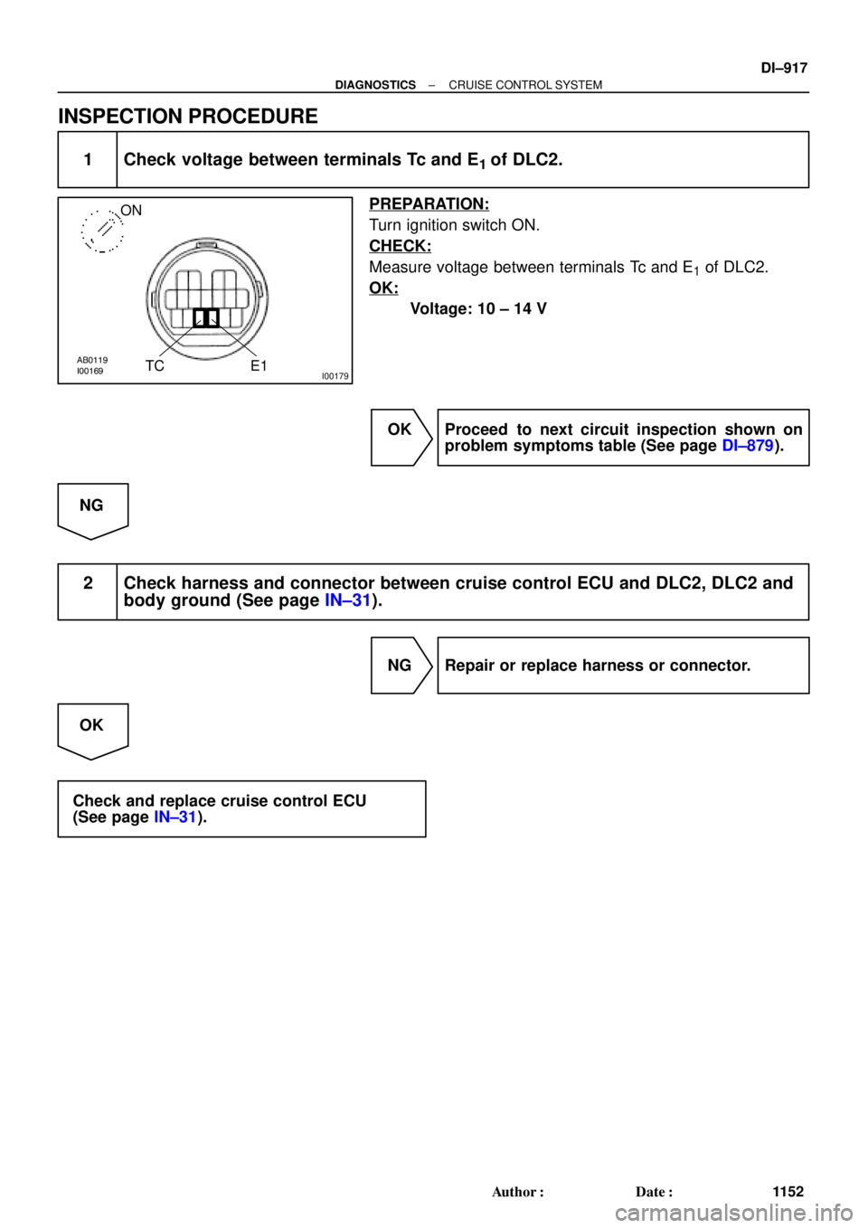
1 Check voltage between terminals Tc and E1 of DLC2.
PREPARATION:
Turn ignition switch ON.
CHECK:
Measure voltage between terminals Tc and E1 of DLC2.
OK:
Voltage: 10 ± 14 V
OK Proceed to next circuit inspection shown on
problem symptoms table (See page DI±879).
NG
2 Check harness and connector between cruise control ECU and DLC2, DLC2 and
body ground (See page IN±31).
NG Repair or replace harness or connector.
OK
Check and replace cruise control ECU
(See page IN±31).
Page 2135 of 4592
 Description
ECM controls the function of i")
S05335
TOYOTA hand±held tester
DLC3
DI1KG±04
N09214
± DIAGNOSTICSENGINE IMMOBILISER SYSTEM
DI±921
1156 Author�: Date�:
PRE±CHECK
1. DIAGNOSIS SYSTEM
(a) Description
ECM controls the function of immobiliser on this vehicle.
Data of the immobiliser or DTC can be read form DLC3 of
the vehicle. When a trouble occurs in immobiliser, MIL
does not light ON but DTC inspection is performed.
Therefore when there seems to be a trouble with immobi-
liser, use TOYOTA hand±held tester or SST to check and
troubleshoot it.
(b) DLC3 INSPECTION
The vehicle's ECM uses ISO 9141±2 for communication.
The terminal arrangement of DLC3 complies with
SAEJ1962 and matches the ISO 9141±2 format.
Tester connectionconditionSpecified condition
7 (Bus � Line) ± 5 (Signal ground)During communicationPulse generation
4 (chassis Ground) ± BodyAlways1 W or less
5 (Signal Ground) ± BodyAlways1 W or less
16 (B+) ± BodyAlways9 ± 14 V
HINT:
If your display shows ºUNABLE TO CONNECT TO VEHICLEº
when you have connected the cable of OBD ll scan tool or TOY-
OTA hand±held tester to DLC3, turned the ignition switch ON
and operated the scan tool, there is a problem on the vehicle
side or tool side.
(1) If communication is normal when the tool is con-
nected to another vehicle, inspect DLC3 on the orig-
inal vehicle.
(2) If communication is still impossible when the tool is
connected to another vehicle, the problem is prob-
ably in the tool itself, so consult the Service Depart-
ment listed in the tool's instruction manual.
Page 2136 of 4592
 Check the DTC (Using TOYOTA hand±held tester)
(1")
F02201
DLC1
TE1E1
BR3904
Normal code
0.25 Sec. 0.25 Sec. DI±922
± DIAGNOSTICSENGINE IMMOBILISER SYSTEM
1157 Author�: Date�:
2. INSPECT DIAGNOSIS
(a) Check the DTC (Using TOYOTA hand±held tester)
(1) Prepare the OBD ll scan tool (complying with SAEJ
1978) or TOYOTA hand±held tester.
(2) Connect the OBD ll scan tool or TOYOTA hand±
held tester to DLC3 under the instrument panel low-
er pad.
(3) Turn the ignition switch ON and turn the OBD ll scan
tool or TOYOTA hand±held tester switch ON.
(4) Use the OBD ll scan tool or TOYOTA hand±held
tester to check the DTCs and freeze frame data;
note them down. (For operating instructions, see
the OBD ll scan tool's instruction book.)
(5) See page DI±924 to confirm the details of the DTCs.
(b) Check the DTC (Using diagnosis check wire)
(1) Turn ignition switch ON.
(2) Using SST, connect between terminals 8 (TE1) and
3 (E1) of DLC1.
SST 09843±18040
(3) Read the diagnostic trouble code from malfunction
indicator lamp.
HINT:
�If a diagnostic trouble code is not output, check the Tc ter-
minal circuit .
�ECM controls the immobiliser function on this vehicle,
DTC is out put with DTC of engine.
As an example, the blinking patterns for codes; normal, 12 and
99 are as shown in the illustration.
Page 2140 of 4592
DI1KJ±04
D01054
E7 E8E10
E11 E9 DI±926
± DIAGNOSTICSENGINE IMMOBILISER SYSTEM
1161 Author�: Date�:
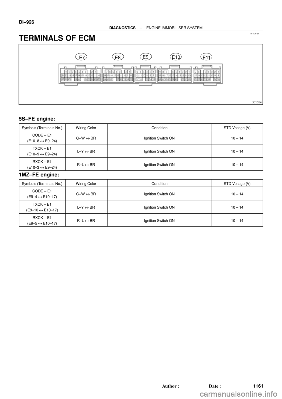
TERMINALS OF ECM
5S±FE engine:
Symbols (Terminals No.)Wiring ColorConditionSTD Voltage (V)
CODE ± E1
(E10±8 e E9±24)G±W e BRIgnition Switch ON10 ± 14
TXCK ± E1
(E10±9 e E9±24)L±Y e BRIgnition Switch ON10 ± 14
RXCK ± E1
(E10±3 e E9±24)R±L e BRIgnition Switch ON10 ± 14
1MZ±FE engine:
Symbols (Terminals No.)Wiring ColorConditionSTD Voltage (V)
CODE ± E1
(E9±4 e E10±17)G±W e BRIgnition Switch ON10 ± 14
TXCK ± E1
(E9±10 e E10±17)L±Y e BRIgnition Switch ON10 ± 14
RXCK ± E1
(E9±5 e E10±17)R±L e BRIgnition Switch ON10 ± 14
Page 2155 of 4592

DI±4
± DIAGNOSTICSENGINE
�The diagnosis system operates in normal mode
during normal vehicle use. It also has a check mode
for technicians to simulate malfunction symptoms
and troubleshoot. Most DTCs use 2 trip detection
logic* to prevent erroneous detection, and ensure
thorough malfunction detection. By switching the
ECM to check mode when troubleshooting, the
technician can cause the MIL to light up for a mal-
function that is only detected once or momentarily.
(TOYOTA hand±held tester only)
(See page DI±3)
�*2 trip detection logic: When a malfunction is first
detected, the malfunction is temporarily stored in
the ECM memory. (1st trip)
If the same malfunction is detected again during the second
drive test, this second detection causes the MIL to light up. (2nd
trip) (However, the ignition switch must be turned OFF between
the 1st trip and 2nd trip.)
�Freeze frame data:
Freeze frame data records the engine condition
when a misfire (DTCs P0300 ± P0304) or fuel trim
malfunction (DTCs P0171 and P0172) or other mal-
function (first malfunction only), is detected. Be-
cause freeze frame data records the engine condi-
tions (fuel system, calculated load, engine coolant
temperature, fuel trim, engine speed, vehicle
speed, etc.) when the malfunction is detected.
When troubleshooting, it is useful for determining
whether the vehicle was running or stopped, the en-
gine was warmed up or not, the air±fuel ratio was
lean or rich, etc. at the time of the malfunction.
�Priorities for troubleshooting.
If troubleshooting priorities for multiple DTCs are given in the
applicable DTC chart, these should be followed.
If no instructions are given, troubleshoot DTCs according to the
following priorities.
(1) DTCs other than fuel trim malfunction (DTCs P0171
and P0172), EGR (DTCs P0401 and P0402), and
misfire (DTCs P0300 ± P0304).
(2) Fuel trim malfunction (DTCs P0171 and P0172),
and EGR (DTCs P0401 and P0402).
(3) Misfire (DTCs P0300 ± P0304).