Page 2184 of 4592
A03011A09257
Engine Coolant
Temp. Sensor
THW
E25 V
E1
ON
E5 Connector
± DIAGNOSTICSENGINE
DI±33
5 Check for short in harness or ECM.
PREPARATION:
(a) Remove the glove compartment (See Pub. No. RM654U,
page SF±64).
(b) Disconnect the E5 connector from the ECM.
HINT:
The engine coolant temp. sensor connector is disconnected.
(c) Turn the ignition switch ON.
CHECK:
Read the temperature value on the OBD II scan tool or TOYO-
TA hand±held tester.
OK:
Temperature value: ±40°C (±40°F)
OK Repair or replace harness or connector.
NG
Check and replace ECM (See page IN±29).
Page 2187 of 4592

FI7052
A00369
ON
VC
(+)
(±)
DI±36
± DIAGNOSTICSENGINE
INSPECTION PROCEDURE
HINT:
�If DTCs P0105, P0106, P0110, P0115, P0120, P0180 and P0190 are output simultaneously, E2 (sen-
sor ground) may be open.
�Read freeze frame data using TOYOTA hand±held tester or OBD II scan tool. Because freeze frame
records the engine conditions when the malfunction is detected. When troubleshooting it is useful for
determining whether the vehicle was running or stopped, the engine was warmed up or not, the air±fuel
ratio was lean or rich, etc. at the time of the malfunction.
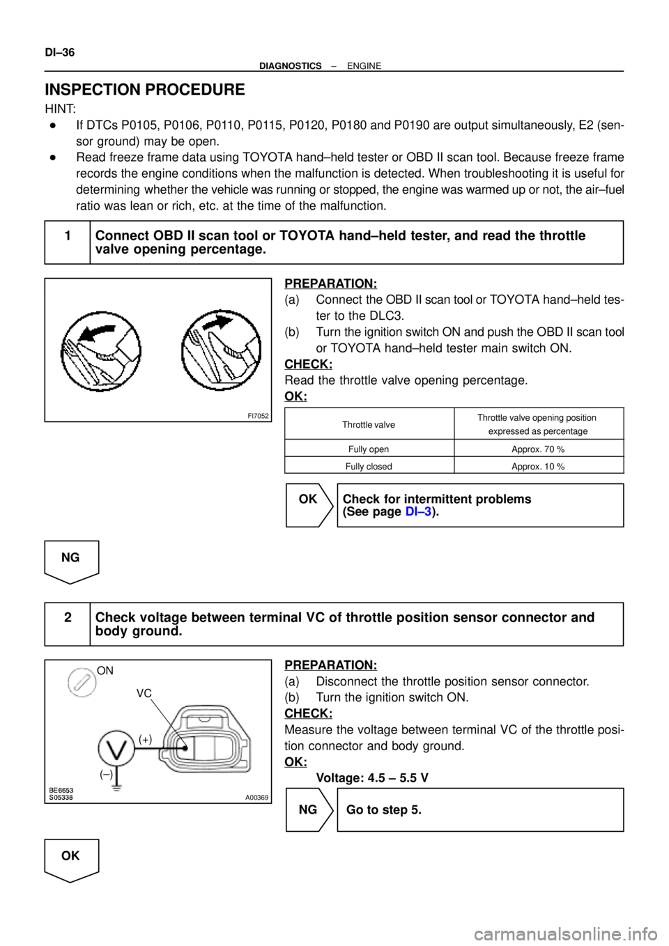
1 Connect OBD II scan tool or TOYOTA hand±held tester, and read the throttle
valve opening percentage.
PREPARATION:
(a) Connect the OBD II scan tool or TOYOTA hand±held tes-
ter to the DLC3.
(b) Turn the ignition switch ON and push the OBD II scan tool
or TOYOTA hand±held tester main switch ON.
CHECK:
Read the throttle valve opening percentage.
OK:
Throttle valveThrottle valve opening position
expressed as percentage
Fully openApprox. 70 %
Fully closedApprox. 10 %
OK Check for intermittent problems
(See page DI±3).
NG
2 Check voltage between terminal VC of throttle position sensor connector and
body ground.
PREPARATION:
(a) Disconnect the throttle position sensor connector.
(b) Turn the ignition switch ON.
CHECK:
Measure the voltage between terminal VC of the throttle posi-
tion connector and body ground.
OK:
Voltage: 4.5 ± 5.5 V
NG Go to step 5.
OK
Page 2188 of 4592

A09283BE6653
A09264
ON
VTA
E2
(+)
(±)
BE6653A03008A09254
ON
VC
E2
(±)
(+)
± DIAGNOSTICSENGINE
DI±37
3 Check throttle position sensor (See Pub. No. RM654U, page SF±29).
NG Replace throttle position sensor.
OK
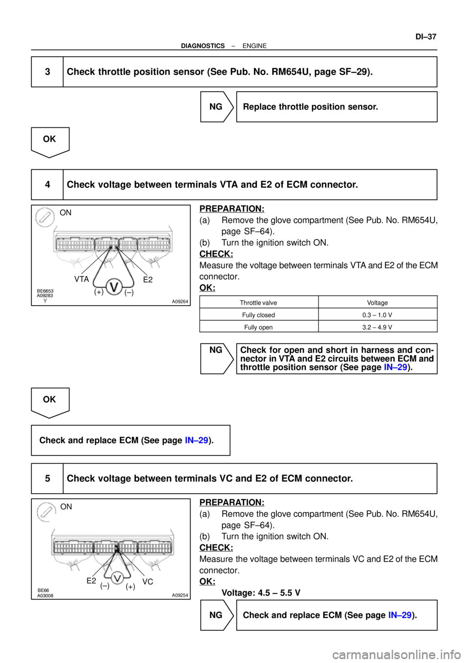
4 Check voltage between terminals VTA and E2 of ECM connector.
PREPARATION:
(a) Remove the glove compartment (See Pub. No. RM654U,
page SF±64).
(b) Turn the ignition switch ON.
CHECK:
Measure the voltage between terminals VTA and E2 of the ECM
connector.
OK:
Throttle valveVoltage
Fully closed0.3 ± 1.0 V
Fully open3.2 ± 4.9 V
NG Check for open and short in harness and con-
nector in VTA and E2 circuits between ECM and
throttle position sensor (See page IN±29).
OK
Check and replace ECM (See page IN±29).
5 Check voltage between terminals VC and E2 of ECM connector.
PREPARATION:
(a) Remove the glove compartment (See Pub. No. RM654U,
page SF±64).
(b) Turn the ignition switch ON.
CHECK:
Measure the voltage between terminals VC and E2 of the ECM
connector.
OK:
Voltage: 4.5 ± 5.5 V
NG Check and replace ECM (See page IN±29).
Page 2198 of 4592

A09296BE6653A09265
ON
HT2
(±) (+)
± DIAGNOSTICSENGINE
DI±47
DTC P0141 Oxygen Sensor Heater Circuit Malfunction
(Bank 1 Sensor 2)
CIRCUIT DESCRIPTION
Refer to DTC P0125 on page DI±40.
DTC No.DTC Detecting ConditionTrouble Area
P0141When heater operates, heater current exceeds 2 A
(2 trip detection logic)�Open or short in heater circuit of heated oxygen sensor
Htd ht
P0141Heater current of 0.2 A or less when heater operates
(2 trip detection logic)�Heated oxygen sensor heater
�ECM
HINT:
�Sensor 1 refers to the sensor closer to the engine body.
�Sensor 2 refers to the sensor farther away from the engine body.
WIRING DIAGRAM
Refer to DTC P0125 on page DI±40.
INSPECTION PROCEDURE
HINT:
Read freeze frame data using TOYOTA hand±held tester or OBD II scan tool. Because freeze frame records
the engine conditions when the malfunction is detected. When troubleshooting it is useful for determining
whether the vehicle was running or stopped, the engine was warmed up or not, the air±fuel ratio was lean
or rich, etc. at the time of the malfunction.
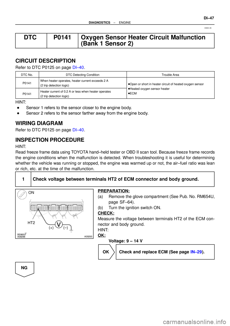
1 Check voltage between terminals HT2 of ECM connector and body ground.
PREPARATION:
(a) Remove the glove compartment (See Pub. No. RM654U,
page SF±64).
(b) Turn the ignition switch ON.
CHECK:
Measure the voltage between terminals HT2 of the ECM con-
nector and body ground.
HINT:
OK:
Voltage: 9 ± 14 V
OK Check and replace ECM (See page IN±29).
NG
DI00X±05
Page 2200 of 4592

± DIAGNOSTICSENGINE
DI±49
DTC P0171 System too Lean (Fuel Trim)
DTC P0172 System too Rich (Fuel Trim)
CIRCUIT DESCRIPTION
Fuel trim refers to the feedback compensation value compared to the basic injection time. Fuel trim includes
short±term fuel trim and long±term fuel trim.
Short±term fuel trim is the short±term fuel compensation used to maintain the air±fuel ratio at its ideal
theoretical value.
The signal from the A/F sensor is approximately proportional to the existing air±fuel ratio, and ECM compar-
ing it with the ideal theoretical value, the ECM reduces fuel volume immediately if the air±fuel ratio is rich
and increases fuel volume if it is lean.
Long±term fuel trim compensates for the deviation from the central value of the short±term fuel trim stored
up by each engine tolerance, and the deviation from the central value due to the passage of time and
changes of environment.
If both the short±term fuel trim and long±term fuel trim exceed a certain value, it is detected as a malfunction
and the MIL lights up.
DTC No.DTC Detecting ConditionTrouble Area
P0171
When air±fuel ratio feedback is stable after engine warming up,
fuel trim is considerably in error on RICH side
(2 trip detection logic)
�Air induction system
�Injector blockage
�Manifold absolute pressure sensor
�Engine coolant temp. sensor
�Fuel shutoff valve for delivery pipe
�Gas leakage on exhaust system
�Air induction system
�Open or short in A/F sensor (bank 1 sensor 1) circuit
�A/F sensor (bank 1 sensor 1)
�ECM
P0172
When air±fuel ratio feedback is stable after engine warming up,
fuel trim is considerably in error on LEAN side
(2 trip detection logic)
�Injector leak, blockage
�Manifold absolute pressure sensor
�Engine coolant temp. sensor
�Ignition system
�Fuel shutoff valve for delivery pipe
�Gas leakage on exhaust system
�Open or short in A/F sensor (bank 1 sensor 1) circuit
�A/F sensor (bank 1 sensor 1)
�ECM
HINT:
�When the DTC P0171 is recorded, the actual air±fuel ratio is on the LEAN side. When DTC P0172 is
recorded, the actual air±fuel ratio is on the RICH side.
�If the vehicle runs out of fuel, the air±fuel ratio is lean and DTC P0171 is recorded. The MIL then comes
on.
�If the total of the short±term fuel trim value and long±term fuel trim value is within +38 %, the system
is functioning normally.
�The A/F sensor output voltage and the short±term fuel trim value can be read using the OBD II scan
tool or TOYOTA hand±held tester.
DI1JW±04
Page 2201 of 4592

DI±50
± DIAGNOSTICSENGINE
�The ECM controls the voltage of AF+ and AF± terminals of ECM to the fixed voltage. Therefore, it is
impossible to confirm the A/F sensor output voltage without OBD II scan tool or TOYOTA hand±held
tester.
�OBD II scan tool (excluding TOYOTA hand±held tester) displays the one fifth of the A/F sensor output
voltage which is displayed on the TOYOTA hand±held tester.
WIRING DIAGRAM
Refer to DTC P0125 on page DI±40.
INSPECTION PROCEDURE
HINT:
Read freeze frame data using TOYOTA hand±held tester or OBD II scan tool. Because freeze frame records
the engine conditions when the malfunction is detected. When troubleshooting it is useful for determining
whether the vehicle was running or stopped, the engine was warmed up or not, the airÅfuel ratio was lean
or rich, etc. at the time of the malfunction.
1 Check air induction system (See Pub. No. RM654U, page SF±1).
NG Repair or replace.
OK
2 Check injector injection (See Pub. No. RM654U, page SF-23).
NG Replace injector.
OK
3 Check manifold absolute pressure sensor (See Pub. No. RM654U, page SF±53)
and engine coolant temperature sensor (See Pub. No. RM654U, page SF±49).
NG Repair or replace.
OK
4 Check for spark and ignition (See page IG±1).
NG Repair or replace.
Page 2206 of 4592
A09295BE6653
A09298
E2
ON
THCNG2
(±) (+)
± DIAGNOSTICSENGINE
DI±55
INSPECTION PROCEDURE
HINT:
If DTCs P0105, P0106, P0110, P0115, P0120, P0180 and P0190 are output simultaneously, E2 (sensor
ground) may be open.
1 Check voltage between terminals THCNG2 and E2 of engine ECU connector.
PREPARATION:
(a) Remove the glove compartment.
(b) Turn the ignition switch ON.
CHECK:
Measure the voltage between terminals THCNG2 and E2 of the
ECM connector.
Temperature °C (°F)Voltage V
±20 (±40)0.66 ± 0.78
20 (68)2.5 ± 2.75
80 (176)4.42 ± 4.52
OK:
OK Check for intermittent problem (See page
DI±3).
NG
2 Check fuel temperature sensor for delivery pipe (See page SF±42).
NG Replace.
OK
3 Check for open and short in harness and connector between engine ECU and
fuel temperature sensor for delivery pipe (See page IN±29).
NG Repair or replace harness or connector.
OK
Check and replace ECM (See page SF±42).
Page 2208 of 4592

BE6653A03008A09254
ON
E2VC
(±)
(+)
A09293BE6653A09297
E2 ONPCNG2
(±) (+)
± DIAGNOSTICSENGINE
DI±57
INSPECTION PROCEDURE
HINT:
If DTC P0105, P0106, P0110, P0115, P0120, P0180 and P0190 are output simultaneously, E2 (sensor
ground) may be open.
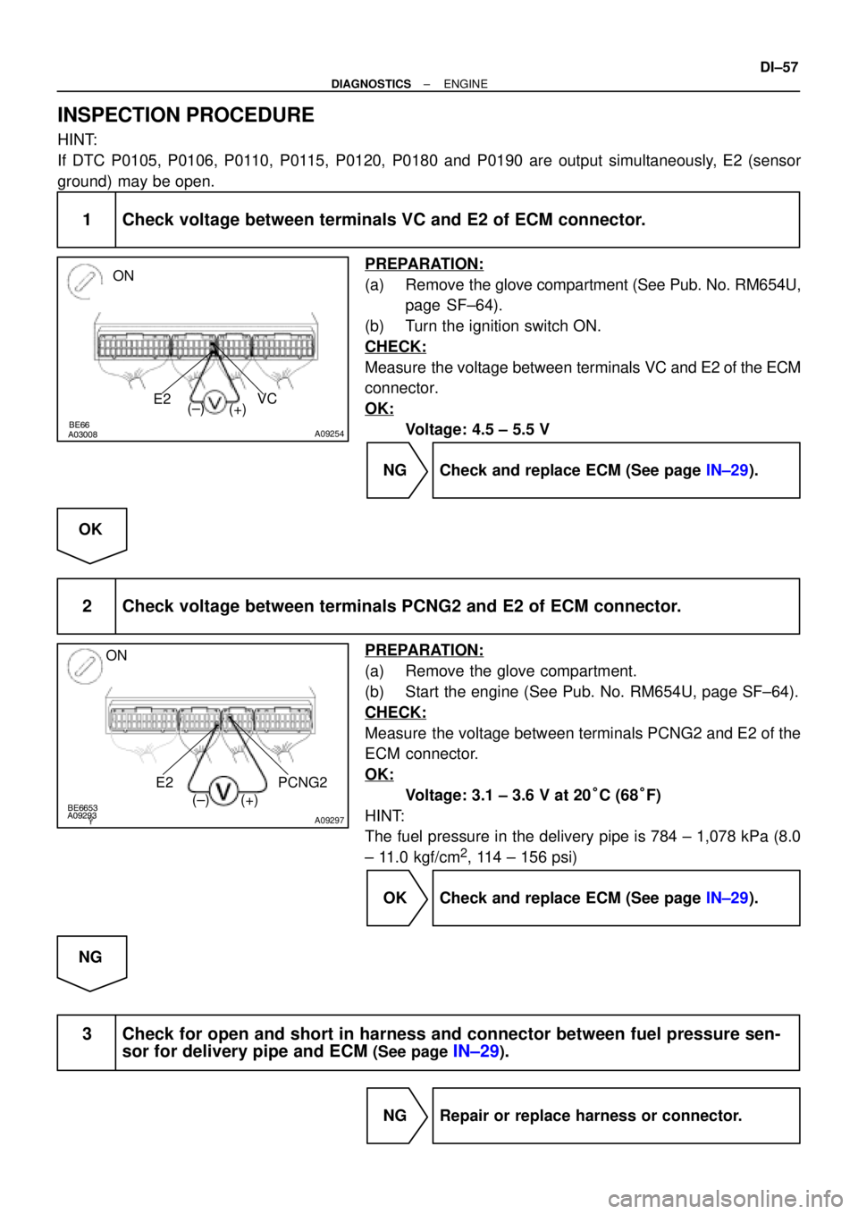
1 Check voltage between terminals VC and E2 of ECM connector.
PREPARATION:
(a) Remove the glove compartment (See Pub. No. RM654U,
page SF±64).
(b) Turn the ignition switch ON.
CHECK:
Measure the voltage between terminals VC and E2 of the ECM
connector.
OK:
Voltage: 4.5 ± 5.5 V
NG Check and replace ECM (See page IN±29).
OK
2 Check voltage between terminals PCNG2 and E2 of ECM connector.
PREPARATION:
(a) Remove the glove compartment.
(b) Start the engine (See Pub. No. RM654U, page SF±64).
CHECK:
Measure the voltage between terminals PCNG2 and E2 of the
ECM connector.
OK:
Voltage: 3.1 ± 3.6 V at 20°C (68°F)
HINT:
The fuel pressure in the delivery pipe is 784 ± 1,078 kPa (8.0
± 11.0 kgf/cm
2, 114 ± 156 psi)
OK Check and replace ECM (See page IN±29).
NG
3 Check for open and short in harness and connector between fuel pressure sen-
sor for delivery pipe and ECM
(See page IN±29).
NG Repair or replace harness or connector.