Page 2008 of 4592
H08301
LG±R P±B
B
BJ3 Junction
ConnectorAirbag Sensor
Assembly
A2119
Tc
11
LG±R 11
Tc
E1DLC1
3 BR
A
J22 (1MZ±FE)
J23 (5S±FE)
Junction Connector
BR (*4)
ECEC BR A
Junction
Connector
6
J7B
J8 C
BR 3
E1Tc DLC2 LG±R (*1)
P±B (*2)
4
B II3
II3
BR
J22
Junction Connector
A A BR BR (*3)J26
Junction
ConnectorB
B
BR (*3)
*1: TMC Made
*2: TMMK Made
*3: California, 1MZ±FE
*4: Except California DI±796
± DIAGNOSTICSSUPPLEMENTAL RESTRAINT SYSTEM
1031 Author�: Date�:
Tc Terminal Circuit
CIRCUIT DESCRIPTION
By connecting terminals Tc and E1 of the DLC1 the airbag sensor assembly is set in the DTC output mode.
The DTCs are displayed by blinking the SRS warning light.
WIRING DIAGRAM
DI1BQ±08
Page 2009 of 4592
AB0117AB0118AB0119
H02309H02314
LOCK ACC
ON
or
AB0118
R14305AB0119
H00030
ACCON
or
E1
Tc
(+) (±)
± DIAGNOSTICSSUPPLEMENTAL RESTRAINT SYSTEM
DI±797
1032 Author�: Date�:
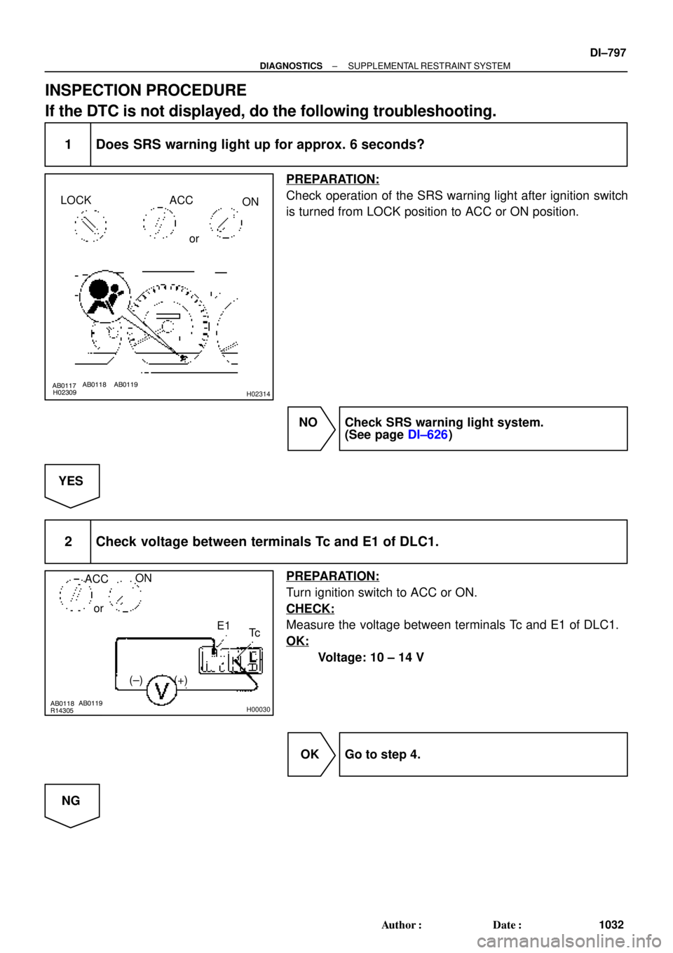
INSPECTION PROCEDURE
If the DTC is not displayed, do the following troubleshooting.
1 Does SRS warning light up for approx. 6 seconds?
PREPARATION:
Check operation of the SRS warning light after ignition switch
is turned from LOCK position to ACC or ON position.
NO Check SRS warning light system.
(See page DI±626)
YES
2 Check voltage between terminals Tc and E1 of DLC1.
PREPARATION:
Turn ignition switch to ACC or ON.
CHECK:
Measure the voltage between terminals Tc and E1 of DLC1.
OK:
Voltage: 10 ± 14 V
OK Go to step 4.
NG
Page 2010 of 4592

(±)
AB0117 AB0118 AB0119H01302H01303
LOCK
ACCON
or
Airbag Sensor Assembly
Tc
DI±798
± DIAGNOSTICSSUPPLEMENTAL RESTRAINT SYSTEM
1033 Author�: Date�:
3 Check")
AB0118
R14304AB0119
H00031
ACCON
orTc
(+)
(±)
AB0117 AB0118 AB0119H01302H01303
LOCK
ACCON
or
Airbag Sensor Assembly
Tc
DI±798
± DIAGNOSTICSSUPPLEMENTAL RESTRAINT SYSTEM
1033 Author�: Date�:
3 Check voltage between terminal Tc of DLC1 and body ground.
CHECK:
Measure the voltage between terminal Tc of DLC1 and body
ground.
OK:
Voltage: 10 ± 14 V
OK Check harness between terminal E1 of DLC1
and body ground.
NG
4 Check airbag sensor assembly.
PREPARATION:
(a) Turn ignition switch to LOCK.
(b) Disconnect negative (±) terminal cable from the battery,
and wait at least for 90 seconds.
(c) Disconnect the airbag sensor assembly connector.
(d) Insert service wire into terminal Tc from back side as
shown in the illustration.
(e) Connect the airbag sensor assembly connector with ser-
vice wire.
(f) Connect negative (±) terminal cable to the battery.
(g) Turn ignition switch to ACC or ON and wait at least for 20
seconds.
(h) Connect service wire of terminal Tc to body ground.
CHECK:
Check operation of SRS warning light.
OK:
SRS waning light comes on.
NOTICE:
Pay due attention to the terminal connecting position to
avoid a malfunction.
OK Check harness between the airbag sensor as-
sembly and DLC1.
NG
Replace airbag sensor assembly.
Page 2034 of 4592
N14695
CTY(+)
DI±822
± DIAGNOSTICSWIRELESS DOOR LOCK CONTROL SYSTEM
1057 Author�: Date�:
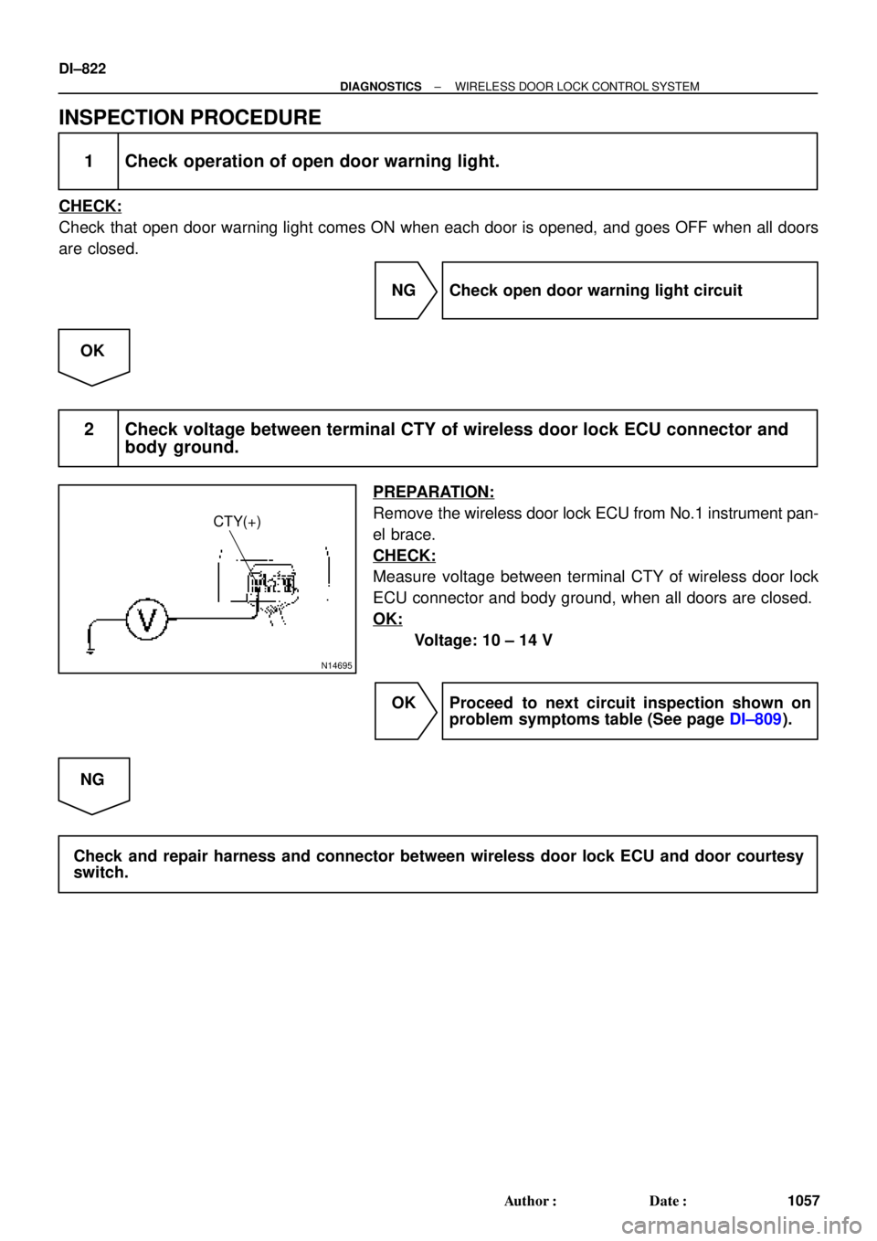
INSPECTION PROCEDURE
1 Check operation of open door warning light.
CHECK:
Check that open door warning light comes ON when each door is opened, and goes OFF when all doors
are closed.
NG Check open door warning light circuit
OK
2 Check voltage between terminal CTY of wireless door lock ECU connector and
body ground.
PREPARATION:
Remove the wireless door lock ECU from No.1 instrument pan-
el brace.
CHECK:
Measure voltage between terminal CTY of wireless door lock
ECU connector and body ground, when all doors are closed.
OK:
Voltage: 10 ± 14 V
OK Proceed to next circuit inspection shown on
problem symptoms table (See page DI±809).
NG
Check and repair harness and connector between wireless door lock ECU and door courtesy
switch.
Page 2039 of 4592

DI06N±05
THEFT DETERRENT SYSTEM Check Sheet
Inspector 's name:
Customer 's Name
Date of VehicleRegistration No.
Registration Year
Frame No.
Odometer Reading / /km
Mile
Weather Conditions
When Problem
Occurred Frequency Problem OccursWeather
Outdoor temperature
/ /
� Constant � Sometimes ( Times per day, month)
� Once only Brought in
� Theft deterrent system cannot be set.
� Indicator light does not flash when the theft deterrent system is set.
(It stays on or does not light at all.)
� Theft deterrent system
does not operate.� When unlocked using the
door lock knob.
� When the engine hood is
opened.
� System cannot be
canceled once set.� When door is unlocked using key or wireless door lock control system.
� When the key is inserted in the ignition key cylinder and turned to ACC or ON
position.
(However, only when the system has never operated)
� When the luggage compartment door is opened with the key.
� System cannot be
canceled during warning
operation.� When door is unlocked using key or wireless door lock control system.
� When the key is inserted in the ignition key cylinder and turned to ACC or ON
position.
� Warning operation starts when the system is set and the door or luggage compartment door is opened with
the key.
� Others.
Date Problem First Occurred
� Fine � Cloudy � Rainy � Snowy
� Various/Others
� Hot � Warm � Cool
� Cold (Approx. 5F ( 5C))
Problem Symptom
Malfunction
� Horns only
� Theft deterrent horn only
� Headlights only
� Taillights only
� Starter cut only
� Door lock operation only
± DIAGNOSTICSTHEFT DETERRENT SYSTEM
DI±827
1062 Author�: Date�:
CUSTOMER PROBLEM ANALYSIS CHECK
Page 2041 of 4592

I00228
0.25 ± 0.05 sec.
0.25 ± 0.05 sec.
ON
OFF
Horns Sounding and Lights Flashing
Pattern
0.2 ± 0.05 sec.
0.55 ± 0.05 sec. ON
OFF
Output of Key Lock Pattern
± DIAGNOSTICSTHEFT DETERRENT SYSTEM
DI±829
1064 Author�: Date�:
(3) About 30 seconds after the process±(2), on the pre-
vious page the Theft Deterrent mode will automati-
cally start.
HINT:
If, while following above steps, you use the key or the remote
control to lock the door, the system will be set to ACTIVE ARM-
ING MODE.
3. THEFT DETERRENT OPERATION
When the system is set to the theft deterrent mode and any of
the following conditions are met, the system sounds the horns
and flashes the headlights and the taillights for about 1 minute.
At the same time locks all doors (If all doors are not locked at
once, the system repeats door locking operation every 0.55 se-
conds during the one±minute alarm time).
Condition
(1) Any of the doors (Including the engine hood and
luggage compartment door) is unlocked or opened
without the key. *1
(2) The battery terminal is disconnected and recon-
nected. *2
(3) The system receives panic signal from remote key-
less entry. *3
*1: Only active arming mode.
*2: When the ignition key is not inserted in the key
cylinder.
Page 2042 of 4592

I00229
0.75 ± 0.1 sec.
1.25 ± 0.1 sec.
ON
OFF
Blinking Pattern Security only: DI±830
± DIAGNOSTICSTHEFT DETERRENT SYSTEM
1065 Author�: Date�:
4. CANCELLATION OF THEFT DETERRENT OPERA-
TION OR MODE
The theft deterrent operation of mode can be cancelled when
any of the following conditions is met.
No.ConditionCancel of OperationCancel of Mode
1Unlock front doors with the keyEffectiveEffective
2Unlock doors with remote keyless entryEffectiveEffective
3Insert key into ignition key cylinder and turn
it to ACC or ON positionEffectiveEffective
4About 1 minute passes after theft deterrent
operation beginsAutomatic stop *1±
5Unlock the luggage compartment door with
the key or keyless entry.UneffectiveEffective
6Unlock the luggage compartment door with
the keyless entry.UneffectiveEffective
7
If the system receives panic signal again or
unlock signal when the system is activated
by panic signal
Effective *2Uneffective
6If the system receives unlock signal when
the system is activated by panic signalEffectiveEffective
*1: The system is set to the theft deterrent mode again in
about 2 seconds after the operation stops, if all doors are
closed.
*2: The alarm caused by the panic signal malces the sys-
tem in the previous condition.
5. INDICATOR LIGHT (LED)
The indicator light functions as shown below according to the
system condition in the theft deterrent mode. It remains OFF in
the initial state.
System ConditionIndicator Light
During set preparation timeON
When the mode is set*OFF
When alarm is activatedON
When the system is temporally cancelled*OFF
*: The indicator flashes with the output from the immobiliser.
6. KEEPING POWER SUPPLY FUNCTION IN CASE OF
DOME FUSE OPEN
Even if the dome fuse blows open on the theft deterrent mode,
the system will keep working on the theft deterrent mode.
Page 2045 of 4592
DI06P±05
I00233
I00234
I00236
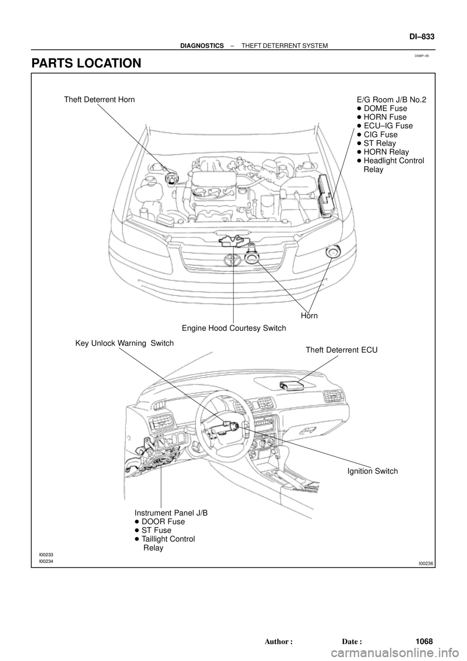
Theft Deterrent Horn
Horn
Engine Hood Courtesy SwitchE/G Room J/B No.2
� DOME Fuse
� HORN Fuse
� ECU±IG Fuse
� CIG Fuse
� ST Relay
� HORN Relay
� Headlight Control
Relay
Theft Deterrent ECU
Ignition Switch Key Unlock Warning Switch
Instrument Panel J/B
� DOOR Fuse
� ST Fuse
� Taillight Control
Relay
± DIAGNOSTICSTHEFT DETERRENT SYSTEM
DI±833
1068 Author�: Date�:
PARTS LOCATION

J23 (5S±FE)
Junction Connector
BR (*4)
ECEC BR A
Junction
Connector
6
J7B
J8 C
BR")