Page 1999 of 4592

H02288
15A CIG
L±R 2Airbag Sensor
Assembly 2
3 4
6 7
6
3B±R
65A IGN
C18 1K
IG 1K
1N1N
C18 Instrument Panel J/B
30A AM2
W±R W±R1
4 40A AM1
2L
1K2A
1B
1K1B
55 W2
1
2 Instrument Panel J/B
AF9 F4F6 FL MAIN
B±G
100A
ALT
Instrument Panel J/B Junction
Connector
W±B7
1J 1NW±BC18
1 Battery
1 1
2
5
B±O
GR
ACCIG2 Fusible Link Block
27
E1 Ignition Switch1 B±RB
± DIAGNOSTICSSUPPLEMENTAL RESTRAINT SYSTEM
DI±787
1022 Author�: Date�:
DTC Normal Source Voltage Drop
CIRCUIT DESCRIPTION
The SRS is equipped with a voltage±increase circuit (DC±DC converter) in the airbag sensor assembly in
case the source voltage drops.
When the battery voltage drops, the voltage±increase circuit (DC±DC converter) functions to increase the
voltage of the SRS to normal voltage.
The diagnosis system malfunction display for this circuit is different from other circuits that is when the SRS
warning light remains lit up and the DTC is a normal code, source voltage drop is indicated.
Malfunction in this circuit is not recorded in the airbag sensor assembly, and the source voltage returns to
normal, the SRS warning light automatically goes off.
DTC No.Diagnosis
(Normal)Source voltage drop
WIRING DIAGRAM
DI1BN±08
Page 2001 of 4592
 (±)
H01249
ON
± DIAGNOSTICSSUPPLEMENTAL RESTRAINT SYSTEM
DI±789
1024 Author�: Date�:
2 Check source voltage.
PREPARATION:
Connect negative")
AB0119H01298H01299
Airbag Sensor Assembly
ON
ACC
IG2
(+) (±)
H01249
ON
± DIAGNOSTICSSUPPLEMENTAL RESTRAINT SYSTEM
DI±789
1024 Author�: Date�:
2 Check source voltage.
PREPARATION:
Connect negative (±) terminal cable to the battery.
CHECK:
(a) Turn ignition switch ON.
(b) Measure the voltage each of IG2 and ACC on the sensor
and operate electric system. (defogger, wiper, headlight,
heater blower, etc.)
OK:
Voltage: 10 ± 14 V
NG Check harness between battery and airbag sen-
sor assembly, and check battery and charging
system.
OK
3 Does SRS warning light turn off?
PREPARATION:
(a) Turn ignition switch to LOCK.
(b) Connect the steering wheel pad connector.
(c) Connect the front passenger airbag assembly connector.
(d) Connect the airbag sensor assembly connectors.
(e) Connect the side airbag assembly connectors.
(f) Connect the seat belt pretensioner connectors.
(g) Connect the side airbag sensor assembly connectors.
(h) Connect the front airbag sensor connectors.
(i) Turn ignition switch to ON.
CHECK:
Operate electric system (defogger, wiper, headlight, heater
blower, etc.) and check that SRS warning light goes off.
NO Check for DTCs. If a DTC is output, perform trou-
bleshooting for the DTC. If a normal code is out-
put, replace airbag sensor assembly.
YES
From the results of the above inspection, the malfunctioning part can now be considered normal.
To make sure of this, use the simulation method to check.
Page 2002 of 4592

H02289
2 Airbag Sensor
Assembly
237
B±Y
12 IG2
C18LG
AB10A
ECU±B
Short Pin
W±R
1W Engine Room J/B No.2
11 B
II3 A
A 3
LG
5DLC1 1 Battery
4 J3 Junction
Connector
1G2J 2A B±G
F4 F6 FL MAINFusible Link Block
1
1
TCP±B7Instrument Panel J/B
C18
B A LAW±R
LG
13
TC B±Y (*1)
LG (*2)
LG±R (*3)
P±B (*4)
II3 LG±R11
B B
TC LG±R J3 Junction
Connector
19
DLC2 SRS Warning Light
*1: TMMK Made, 1MZ±FE
*2: Except *1
*3: TMC Made
*4: TMMK Made DI±790
± DIAGNOSTICSSUPPLEMENTAL RESTRAINT SYSTEM
1025 Author�: Date�:
SRS Warning Light Circuit Malfunction (Always lights up, when
ignition switch is in LOCK position.)
CIRCUIT DESCRIPTION
The SRS warning light is located on the combination meter.
When the SRS is normal, the SRS warning light lights up for approx. 6 seconds after the ignition switch is
turned from the LOCK position to ACC or ON position, and then turns off automatically.
If there is a malfunction in the SRS, the SRS warning light lights up to inform the driver of the abnormality.
When terminals Tc and E1 of the DLC1 are connected, the DTC is displayed by blinking the SRS warning
light.
WIRING DIAGRAM
DI1BO±08
Page 2003 of 4592
AB0117H01293H01295
Airbag Sensor Assembly
LOCK
± DIAGNOSTICSSUPPLEMENTAL RESTRAINT SYSTEM
DI±791
1026 Author�: Date�:
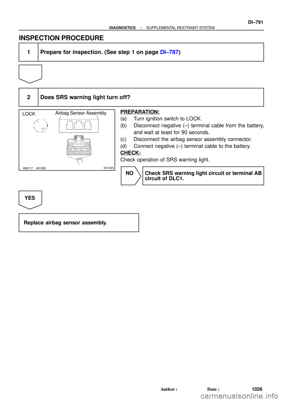
INSPECTION PROCEDURE
1 Prepare for inspection. (See step 1 on page DI±787)
2 Does SRS warning light turn off?
PREPARATION:
(a) Turn ignition switch to LOCK.
(b) Disconnect negative (±) terminal cable from the battery,
and wait at least for 90 seconds.
(c) Disconnect the airbag sensor assembly connector.
(d) Connect negative (±) terminal cable to the battery.
CHECK:
Check operation of SRS warning light.
NO Check SRS warning light circuit or terminal AB
circuit of DLC1.
YES
Replace airbag sensor assembly.
Page 2004 of 4592

CIRCUIT DES")
N14677
Fuse
DI±792
± DIAGNOSTICSSUPPLEMENTAL RESTRAINT SYSTEM
1027 Author�: Date�:
SRS Warning Light Circuit Malfunction (Does not light up, when
ignition switch is turned to ACC or ON.)
CIRCUIT DESCRIPTION
The SRS warning light is located on the combination meter.
When the SRS is normal, the SRS warning light lights up for approx. 6 seconds after the ignition switch is
turned from LOCK position to ACC or ON position, and then turns off automatically.
If there is a malfunction in the SRS, the SRS warning light lights up to inform the driver of the abnormality.
When terminals Tc and E1 of the DLC1 are connected, the DTC is displayed by blinking the SRS warning
light.
WIRING DIAGRAM
See page DI±790.
INSPECTION PROCEDURE
1 Check ECU±B Fuse.
PREPARATION:
Remove ECU±B fuse.
CHECK:
Check continuity of ECU±B fuse.
OK:
Continuity
HINT:
�Fuse may be burnt out even if it appears to be OK during
visual inspection.
�If fuse is OK, install it.
NG Go to step 5.
OK
2 Prepare for inspection. (See step 1 on page DI±787)
DI1BP±08
Page 2005 of 4592
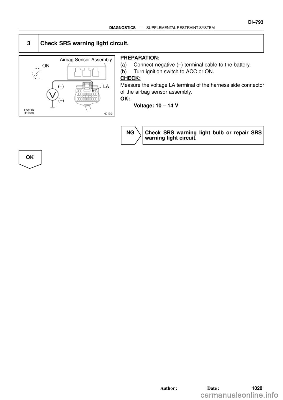
AB0119H01300
H01301
Airbag Sensor Assembly
ON
LA
(+)
(±)
± DIAGNOSTICSSUPPLEMENTAL RESTRAINT SYSTEM
DI±793
1028 Author�: Date�:
3 Check SRS warning light circuit.
PREPARATION:
(a) Connect negative (±) terminal cable to the battery.
(b) Turn ignition switch to ACC or ON.
CHECK:
Measure the voltage LA terminal of the harness side connector
of the airbag sensor assembly.
OK:
Voltage: 10 ± 14 V
NG Check SRS warning light bulb or repair SRS
warning light circuit.
OK
Page 2006 of 4592
AB0119H08325H02309H08324
Airbag
Sensor
Assembly
Side Airbag
Sensor (RH)Spiral
Cable
P Squib
D Squib
P/T Squib (LH)
Front Airbag
Sensor (LH)
Side Squib (RH)
ON
Side Airbag
Sensor (LH)
P/T Squib (RH)Side Squib (LH)
Front Airbag
Sensor (RH)
DI±794
± DIAGNOSTICSSUPPLEMENTAL RESTRAINT SYSTEM
1029 Author�: Date�:
4 Does SRS warning light come on?
PREPARATION:
(a) Disconnect negative (±) terminal cable from the battery.
(b) Connect the airbag sensor assembly connector.
(c) Connect negative (±) terminal cable to the battery, and
wait at least for 2 seconds.
(d) Turn ignition switch to ACC or ON.
CHECK:
Check operation of SRS warning light.
NO Check terminal LA of airbag sensor assembly.
If normal, replace airbag sensor assembly.
YES
From the results of the above inspection, the malfunctioning part can now be considered normal.
To make sure of this, use simulation method to check.
Page 2007 of 4592
± DIAGNOSTICSSUPPLEMENTAL RESTRAINT SYSTEM
DI±795
1030 Author�: Date�:
5 Is new ECU±B fuse burnt out again?
NO Using simulation method, reproduce malfunc-
tion symptoms. (See page IN±21)
YES
Check harness between ECU±B fuse and
SRS warning light.
Spiral
Cable
P Squib
D Squib
P/T Squib (LH)
Front Airbag
Sensor (LH)
Side Squib (RH)
ON
Side Airbag
Sensor (LH)
P/T Squib (RH)Si")