Page 1829 of 4592

F00114
TRAC OFF
Indicator LightABS & TRAC ECU
CJ32 C10 R±L7
DLC2
17 J/CJ/C
2
IG3
TRC
Instrument Panel J/B
1D
J4 D319
L
A16
D R±L
C10LL
L
A16 TRAC Cut Switch
W±B12
11
LGWT
CSW
J7
J114 1
IGJ8
A 8
1JW±B
A J/C
1J7 Instrument Panel J/B
W±B
A J/CTRAC OFF
Indicator LightABS & TRAC ECU
C
C10 R±L7
DLC2
17 J/CJ/C
2
IG3
TRC
Instrument Panel J/B
1D
J4 D319
L
A16
D R±L
C10LL
L
A16 TRAC Cut Switch
W±B12
11
LGWT
CSW
J7
J114 1
IGJ8
A 8
1JW±B
A J/C
1J7 Instrument Panel J/B
W±B
A J/CTRAC OFF
Indicator LightABS & TRAC ECU
C
C10 R±L7
DLC2
17 J/CJ/C
2
IG3
TRC
Instrument Panel J/B
1D
J4 D319
L
A16
D R±L
C10LL
L
A16 TRAC Cut Switch
W±B12
11
LGWT
CSW
J7
J114 1
IGJ8
A 8
1JW±B
A J/C
1J7 Instrument Panel J/B
W±B
A J/CTRAC OFF
Indicator LightABS & TRAC ECU
C10 R±L7
DLC2
17 J/CJ/C
2
IG3
TRC
Instrument Panel J/B
1D
J4 D319
L
A16
D R±L
C10LL
L
A16 TRAC Cut Switch
W±B12
11
LGWT
CSW
J7
J114 1
IGJ8
A 8
1JW±B
A J/C
1J7 Instrument Panel J/B
W±B
A J/C
TRAC OFF
Indicator LightABS & TRAC ECU
C10
GAUGER±L7
DLC2
17 J/CJ/C
2
IG3
TRC
Instrument Panel J/B
1D
J4 D319
L
A16
D R±L
C10LL
L
A16 TRAC Cut Switch
W±B12
11
LGWT
CSW
J7
J114 1
IGJ8
A 8
1JW±B
A J/C
1J7 Instrument Panel J/B
W±B
A J/CJ32 J32
± DIAGNOSTICSABS & TRACTION CONTROL SYSTEM
DI±617
852 Author�: Date�:
TRAC OFF Indicator, TRAC Cut Switch Circuit
CIRCUIT DESCRIPTION
This is the TRAC control main switch. When the TRAC cut switch is pushed on, TRAC control goes off and
the TRAC OFF indicator lights up. This indicator blinks for warnings when the trouble occurs and for
displaying DTC.
WIRING DIAGRAM
INSPECTION PROCEDURE
1 Check DTC.
Check DTC on page DI±574.
YES Repair circuit indicated by the code output.
NO
DI04Y±04
Page 1830 of 4592
F00052
1 4
(+)(±) 32
DI±618
± DIAGNOSTICSABS & TRACTION CONTROL SYSTEM
853 Author�: Date�:
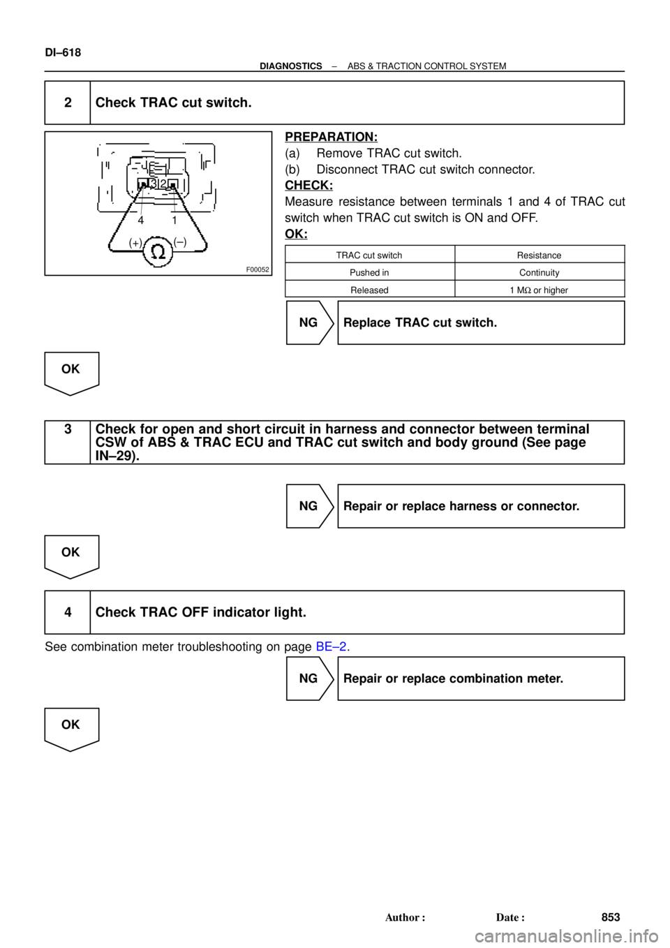
2 Check TRAC cut switch.
PREPARATION:
(a) Remove TRAC cut switch.
(b) Disconnect TRAC cut switch connector.
CHECK:
Measure resistance between terminals 1 and 4 of TRAC cut
switch when TRAC cut switch is ON and OFF.
OK:
TRAC cut switchResistance
Pushed inContinuity
Released1 MW or higher
NG Replace TRAC cut switch.
OK
3 Check for open and short circuit in harness and connector between terminal
CSW of ABS & TRAC ECU and TRAC cut switch and body ground (See page
IN±29).
NG Repair or replace harness or connector.
OK
4 Check TRAC OFF indicator light.
See combination meter troubleshooting on page BE±2.
NG Repair or replace combination meter.
OK
Page 1831 of 4592
± DIAGNOSTICSABS & TRACTION CONTROL SYSTEM
DI±619
854 Author�: Date�:
5 Check for open and short circuit in harness and connector between terminal WT
of ABS & TRAC ECU and TRAC OFF indicator light (See page IN±31).
NG Repair or replace harness or connector.
OK
Check and replace ABS & TRAC ECU.
Page 1832 of 4592

F00097
Instrument Panel J/B
1DR±L
C10 C8 IND 2J/C
J4LG18
A16 R±LSLIP Indicator LightABS & TRAC ECU
IG3 75
LG3
D D Instrument Panel J/B
1DR±L
C10 C8 IND 2J/C
J4LG18
A16 R±LSLIP Indicator LightABS & TRAC ECU
IG3 75
LG3
D D Instrument Panel J/B
1DR±L
C10 C8 IND 2J/C
J4LG18
A16 R±LSLIP Indicator LightABS & TRAC ECU
IG3 75
LG3
D D Instrument Panel J/B
1DR±L
C10 C8 IND 2J/C
J4LG18
A16 R±LSLIP Indicator LightABS & TRAC ECU
IG3 75
LG3
D D Instrument Panel J/B
1DR±L
C10 C8 IND 2J/C
J4LG18
A16 R±LSLIP Indicator LightABS & TRAC ECU
IG3 75
LG3
D D Instrument Panel J/B
1DR±L
C10 C8 IND 2J/C
J4LG18
A16 R±LSLIP Indicator LightABS & TRAC ECU
IG3 75
LG3
D DInstrument Panel J/B
1DR±L
C10 C8 IND 2
GAUGEJ/C
J4LG18
A16 R±LSLIP Indicator LightABS & TRAC ECU
IG3 75
LG3
D D
DI±620
± DIAGNOSTICSABS & TRACTION CONTROL SYSTEM
855 Author�: Date�:
SLIP Indicator Light Circuit
CIRCUIT DESCRIPTION
The SLIP indicator blinks during TRAC operation.
WIRING DIAGRAM
INSPECTION PROCEDURE
1 Check SLIP indicator light.
See combination meter troubleshooting on page BE±2.
NG Repair or replace combination meter.
OK
2 Check for short circuit in harness and connector between ABS & TRAC ECU and
SLIP indicator light (See page IN±31).
NG Repair or replace harness or connector.
OK
Check and replace ABS & TRAC ECU.
DI04Z±04
Page 1833 of 4592
F00120
DLC2
ECII3
ADLC1 6
12
Tc
BJ3
J22J/C
II3A15 IK2 J8
11 J7 E
1
C
BRA
ABR BRBRJ/C
BR
TcTc
E
1LG±RJ/C
BB B LG±R LG±RLG±RABS & TRAC ECU
9
34
113
DLC2
ECII3
ADLC1 6
12
Tc
BJ3
J22J/CLG±R
*1
II3A15 IK2 J8
11 J7 E
1
C
BRA
ABR BRBRJ/C
BR
TcTc
E
1LG±RJ/C
BB B LG±R LG±RLG±RABS & TRAC ECU
9
34
113
P±B*2
*1:
TMC Made*2: TMMK Made
F02607 F00445F02612
DLC2
DLC1
Tc E
1
Tc E
1
± DIAGNOSTICSABS & TRACTION CONTROL SYSTEM
DI±621
856 Author�: Date�:
Tc Terminal Circuit
CIRCUIT DESCRIPTION
Connecting between terminals Tc and E1 of the DLC1 or the DLC2 causes the ECU to display the DTC by
blinking the ABS warning light and TRAC OFF indicator light.
WIRING DIAGRAM
INSPECTION PROCEDURE
1 Check voltage between terminals Tc and E1 of DLC2 or DLC1.
CHECK:
(a) Turn the ignition switch ON.
(b) Measure voltage between terminals Tc and E
1 of DLC2 or
DLC1.
OK:
Voltage: 10 ± 14 V
OK If ABS warning light does not blink even after Tc
and E
1 are connected, the ECU may be defec-
tive.
NG
DI4KY±01
Page 1836 of 4592
DI1AX±04
Vehicle Brought to Workshop
Customer Problem Analysis
Warning Light Check
DTC Check
DTC Chart
DI±633
Circuit Inspection
Remains ON
Normal and Malfunction Code
Symptom Simulation
DTC Check
Identification of Problem
Warning Light Check
Confirmation Test
Warning Light ON
Warning Light Remains OFF
END
Normal
Normal
1
2
3
4
7
Repair
85
6
Step,:Diagnostic steps permitting the use
of the TOYOTA hand±held tester.3
6 DI±625
DI±626IN±21
DI±640 DI±626
DI±626
DI±626 DI±624
± DIAGNOSTICSSUPPLEMENTAL RESTRAINT SYSTEM
859 Author�: Date�:
SUPPLEMENTAL RESTRAINT SYSTEM
HOW TO PROCEED WITH TROUBLESHOOTING
Page 1837 of 4592
DI15Z±07
Supplemental Restraint System Check Sheet
Date Problem Occurred
Customer 's Name
Registration No.
Registration Year
Frame No.
Odometer Reading
Weather
Temperature
Vehicle Operation
Road Conditions
Details Of Problem
Vehicle Inspection, Repair Histo-
ry Prior to Occurrence of Mal-
function (Including Supplemen-
tal Restraint System)
Diagnosis System Inspection
SRS Warning Light
Inspection
DTC Inspection1st Time
2nd Time
1st Time
2nd TimeInspector 's
Name
Fine Cloudy Rainy Snowy Other
Approx.
Starting Idling
Driving [ Constant speed Acceleration Deceleration
Other ]
Remains ON Sometimes Light Up Does Not Light Up
Remains ON Sometimes Light Up
Does Not Light Up
Normal Code Malfunction Code
Normal Code Malfunction Code[ Code. ]
[ Code. ]km
Miles //
//
// Date Vehicle Brought In
± DIAGNOSTICSSUPPLEMENTAL RESTRAINT SYSTEM
DI±625
860 Author�: Date�:
CUSTOMER PROBLEM ANALYSIS CHECK
Page 1838 of 4592
 Turn the ignition switch to the ACC or ON position")
DI4L1±01
H02309
R13006
DLC1
E1 Tc
DI±626
± DIAGNOSTICSSUPPLEMENTAL RESTRAINT SYSTEM
861 Author�: Date�:
PRE±CHECK
1. SRS WARNING LIGHT CHECK
(a) Turn the ignition switch to the ACC or ON position and
check that the SRS warning light lights up.
(b) Check that the SRS warning light goes out after approx.
6 seconds.
HINT:
�When the ignition switch is at ACC or ON and the SRS
warning light remains on or flashes, the airbag sensor as-
sembly has detected a malfunction code.
�If, after approx. 6 seconds have elapsed, the SRS warn-
ing light sometimes lights up or the SRS warning light
lights up even when the ignition switch is OFF, a short in
the SRS warning light circuit can be considered likely.
Proceed to ºSRS warning light circuit malfunctionº on
page DI±790, DI±792.
2. DTC CHECK (Using diagnosis check wire)
(a) Present troubles codes:
Output the DTC.
(1) Turn the ignition switch to the ACC or ON position
and wait for approx. 20 seconds.
(2) Using SST, connect terminals Tc and E1 of the
DLC1.
SST 09843±18020
NOTICE:
Pay due attention to the terminal connecting position to
avoid a malfunction.
(b) Past troubles codes:
Output the DTC.
(1) Using service wire, connect Terminals Tc and E1 of
the DLC1.
SST 09843±18020
(2) Turn the ignition switch to the ACC or ON position
and wait for approx. 20 seconds.
NOTICE:
Pay due attention to the terminal connecting position to
avoid a malfunction.