Page 3457 of 4592

SF08K±03
B06390
VSV Connector for
EVAP
Ground Cable
PCV Hose
Air Intake Chamber
Assembly
ECT Sensor
Connector ECT Sender
Gauge ConnectorEGR Valve Position
Sensor Connector
IAC Valve
Connector
VSV Connector
for EGR
VSV Connector for ACIS
Engine Wire
Engine Coolant
Reservoir HoseAir Assist Hose
Water Bypass Hose No.2 EGR Pipe
Throttle Position
Sensor Connector
No.1 Engine
HangerBrake Booster
Vacuum Hose Air Intake Chamber Stay
Water OutletPS Pressure Tube
�Gasket
19.5 (200, 14)
39 (400, 19)12 (120, 19)
15 (150, 11)
�Gasket
43 (440, 32)
Ground Starp
DLC1
�Gasket
15 (150, 11)
Grand Strap
Connector
�Gasket
39 (400, 29)
V±Bank Cover
Accelerator Cable
Throttle Cable
Air Cleaner
Hose
Purge HoseEGR Gas Temperature
Sensor Connector
Vacuum
HoseWater Bypass Hose
Fuel Inlet Hose
Heater Hose
Intake Manifold Assembly
Injector Connector x 9
Knock Sensor
Connector
Upper Radiator
Hose
Engine
Wire
Band
High±Tension Cord
Set �Gasket
: Specified torque
�Non±reusable partN´m (kgf´cm, ft´lbf)
�Retainer
Knock Sensor
SF±66
± SFI (1MZ±FE)KNOCK SENSOR
1565 Author�: Date�:
KNOCK SENSOR
COMPONENTS
Page 3537 of 4592
SR06T±01
W03350
Stabilizer Bar
No.1 Fuel Tube Protector
Intermediate Shaft
Assembly
Pressure Feed Tube
PS Gear Assembly
N´m (kgf´cm, ft´lbf) : Specified torque
Non±reusable part
For use with SSTClamp Plate
Return
Tube
�
*� Cotter pin �
19 (195, 14)
19 (195, 14)
25 (250, 18)
*32 (326, 24)
181 (1,850, 134)
49 (500, 36)
49 (500, 36)
35 (360, 26)
181 (1,850, 134)
10 (100, 7)
± STEERINGPOWER STEERING GEAR
SR±31
2126 Author�: Date�:
POWER STEERING GEAR
COMPONENTS
Page 3540 of 4592
SR06U±01
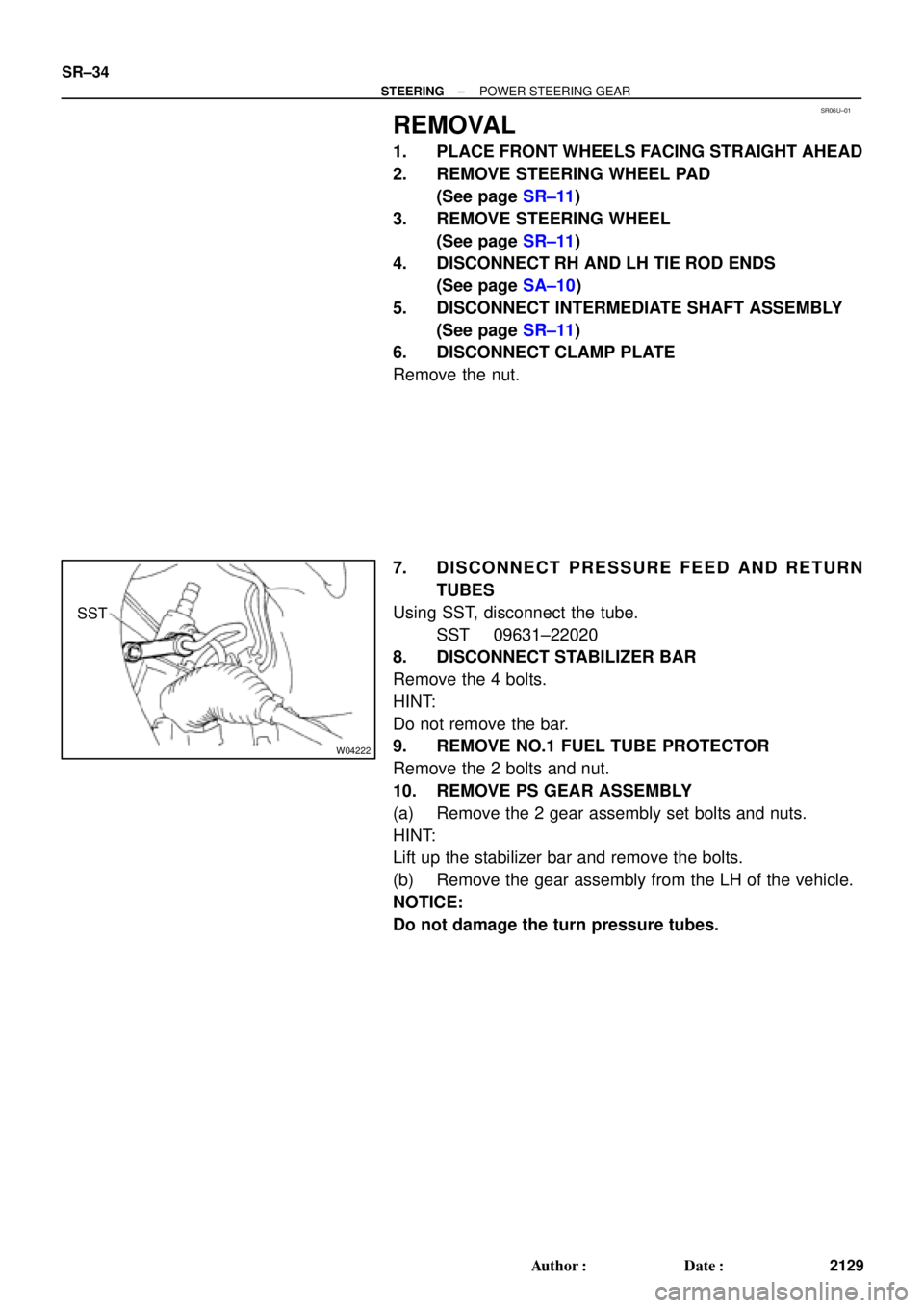
W04222
SST SR±34
± STEERINGPOWER STEERING GEAR
2129 Author�: Date�:
REMOVAL
1. PLACE FRONT WHEELS FACING STRAIGHT AHEAD
2. REMOVE STEERING WHEEL PAD
(See page SR±11)
3. REMOVE STEERING WHEEL
(See page SR±11)
4. DISCONNECT RH AND LH TIE ROD ENDS
(See page SA±10)
5. DISCONNECT INTERMEDIATE SHAFT ASSEMBLY
(See page SR±11)
6. DISCONNECT CLAMP PLATE
Remove the nut.
7. DISCONNECT PRESSURE FEED AND RETURN
TUBES
Using SST, disconnect the tube.
SST 09631±22020
8. DISCONNECT STABILIZER BAR
Remove the 4 bolts.
HINT:
Do not remove the bar.
9. REMOVE NO.1 FUEL TUBE PROTECTOR
Remove the 2 bolts and nut.
10. REMOVE PS GEAR ASSEMBLY
(a) Remove the 2 gear assembly set bolts and nuts.
HINT:
Lift up the stabilizer bar and remove the bolts.
(b) Remove the gear assembly from the LH of the vehicle.
NOTICE:
Do not damage the turn pressure tubes.
Page 3555 of 4592
 Install the gear assembly from the LH of the vehicle.
NOTICE")
SR06Y±01
W04224
SST
Fulcrum
Length
± STEERINGPOWER STEERING GEAR
SR±49
2144 Author�: Date�:
INSTALLATION
1. INSTALL PS GEAR ASSEMBLY
(a) Install the gear assembly from the LH of the vehicle.
NOTICE:
Do not damage the turn pressure tubes.
(b) Torque the 2 gear assembly set bolts and nuts.
Torque: 181 N´m (1,850 kgf´cm, 134 ft´lbf)
HINT:
Lift up the stabilizer bar and install the bolts.
2. INSTALL NO.1 FUEL TUBE PROTECTOR
Install the 2 bolts and nut.
3. CONNECT STABILIZER BAR
Torque the 4 bolts.
Torque: 19 N´m (195 kgf´cm, 14 ft´lbf)
4. CONNECT PRESSURE FEED AND RETURN TUBES
Using SST, connect the tube.
SST 09631±22020
Torque: 32 N´m (326 kgf´cm, 24 ft´lbf)
HINT:
�Use a torque wrench with a fulcrum length of 300 mm
(11.81 in.).
�This torque value is effective in case that SST is parallel
to a torque wrench.
5. CONNECT CLAMP PLATE
Torque the nut.
Torque: 10 N´m (100 kgf´cm, 7 ft´lbf)
6. CONNECT INTERMEDIATE SHAFT ASSEMBLY
(See page SR±16)
7. CONNECT RH AND LH TIE ROD ENDS
(See page SA±10)
8. POSITION FRONT WHEELS FACING STRAIGHT
AHEAD
HINT:
Do it with the front of the vehicle jacked up.
9. CENTER SPIRAL CABLE
(See page SR±16)
10. INSTALL STEERING WHEEL
(a) Install the wheel at straight±ahead position.
(b) Temporarily tighten the wheel set nut.
(c) Connect the connector.
11. BLEED POWER STEERING SYSTEM
(See page SR±4)
12. CHECK STEERING WHEEL CENTER POINT
Page 3784 of 4592

45 mph
(72 km/h)
25 mph
(40 km/h)
Id")
READINESS MONITOR DRIVE PATTERNS ± EG003-02 RevisedMarch 29, 2002
Page 14 of 23
DRIVE PATTERN NO. 5: EVAP Monitor
(Internal Pressure Monitor/Non±Intrusive Type)
45 mph
(72 km/h)
25 mph
(40 km/h)
Idling
IG SW off
Soak
(1b)5 min
(2a)15 min
(2b) Warm up
ECT.176�F
(1a)
Cold Soak Drive Pattern
Cold Soak Preconditions
The monitor will not run unless:
�MIL is OFF.
�Fuel level is between 1/2 to 3/4 full (for faster completion)
.
�Altitude is 7800 feet (2400 m) or less.
IMPORTANT:
A cold soak must be performed prior to conducting the drive pattern to complete the
Internal Pressure Readiness Monitor.
Cold Soak Procedure
1a. Start the engine and allow ECT (Coolant Temp) to reach 176�F (80�C) or greater.
(This can be done by letting the engine idle or by driving the vehicle.)
1b. Let the vehicle cold soak for 8 hours or until the difference between IAT (Intake
Air) and ECT (Coolant Temp) is less than 13�F (7�C).
�Example 1
�ECT (Coolant Temp) = 75�F (24�C).
�IAT (Intake Air) = 60�F (16�C).
�Difference between ECT (Coolant Temp) and IAT (Intake Air) is 15�F (8�C).
%The monitor will not run because the difference between ECT (Coolant
Temp) and IAT (Intake Air) is greater than 13�F (7�C).
�Example 2
�ECT (Coolant Temp) = 70�F (21�C).
�IAT (Intake Air) = 68�F (20�C).
�Difference between ECT (Coolant Temp) and IAT (Intake Air) is 2�F (1�C).
%The monitor will run because the difference between ECT (Coolant Temp)
and IAT (Intake Air) is less than 13�F (7�C).
Readiness
Monitor
Drive
Patterns:
EVAP
Monitors
Page 3785 of 4592

READINESS MONITOR DRIVE PATTERNS ± EG003-02 RevisedMarch 29, 2002
Page 15 of 23
Drive Pattern Preconditions
The monitor will not run unless:
�MIL is OFF.
�Fuel level is between 1/2 to 3/4 full (for faster completion)
.
�Altitude is 7800 feet (2400 m) or less.
�ECT (Coolant Temp) is between 40�F and 95�F (4.4�C ± 35�C).
�IAT (Intake Air) is between 40�F and 95�F (4.4�C ± 35�C).
�Cold Soak Procedure has been completed.
NOTE:
Before starting the engine, the difference between ECT (Coolant Temp) and IAT (Intake
Air) must be less than 13�F (7�C). (Refer to Examples 1 and 2 on previous page.)
Drive Pattern Procedure
�Connect the OBDII Scantool to DLC3 to check monitor status and preconditions.
�Release the pressure in the fuel tank by removing and then reinstalling the fuel tank
cap.
�Start the engine and begin driving as directed.
NOTE:
�Do not turn the ignition off until the drive pattern is complete.
�Drive on smooth roads to reduce excessive fuel sloshing.
2a. Start the engine and as soon as safely possible begin driving at approximately 45
mph (72km/h) for 5 minutes. (See illustration on previous page.)
2b. Drive the vehicle at approximately 25 mph (40 km/h) for 15 minutes and include a
minimum of two stops for approximately 30 seconds. (See illustration on previous
page.)
The monitor should complete within approximately 20 minutes. If it does not, ensure
preconditions are met and repeat the drive pattern process beginning with the Cold Soak
Procedure.
NOTE:
The readiness status may not switch to ªcompleteº after the first drive pattern trip if a
Pending Code has been set (first trip for a two±trip DTC).
�Pending Codes are available from the DTC Info Menu in Enhanced OBDII.
�Pending Codes indicate a POTENTIAL problem was detected. A second trip is
needed to confirm the DTC prior to diagnosis.
�Once a second trip is completed, a current DTC will be stored. Readiness
Monitor
Drive
Patterns:
EVAP
Monitors
(Continued)
Page 3786 of 4592

Idling
IG SW off
Warm up
(2a) Soak
(1a)15 ±")
READINESS MONITOR DRIVE PATTERNS ± EG003-02 RevisedMarch 29, 2002
Page 16 of 23
DRIVE PATTERN NO. 6: EVAP Monitor (Vacuum Pressure Monitor/Intrusive Type)
Idling
IG SW off
Warm up
(2a) Soak
(1a)15 ±50 min
(When the Readiness Monitor or
DTC is set, this test is complete.)
(2c)
10 sec
(2b)
3,000 rpm
Cold Soak Preconditions
The monitor will not run unless:
�MIL is OFF.
�Fuel level is between 1/2 to 3/4 full (for faster completion)
.
�Altitude is 7800 feet (2400 m) or less.
Cold Soak Procedure
1a. Let the vehicle cold soak for 8 hours or until the difference between IAT (Intake
Air) and ECT (Coolant Temp) is less than 13�F (7�C).
�Example 1
�ECT (Coolant Temp) = 75�F (24�C).
�IAT (Intake Air) = 60�F (16�C).
�Difference between ECT (Coolant Temp) and IAT (Intake Air) is 15�F (8�C).
%The monitor will not run because the difference between ECT (Coolant
Temp) and IAT (Intake Air) is greater than 13�F (7�C).
�Example 2
�ECT (Coolant Temp) = 70�F (21�C).
�IAT (Intake Air) = 68�F (20�C).
�Difference between ECT (Coolant Temp) and IAT (Intake Air) is 2�F (1�C).
%The monitor will run because the difference between ECT (Coolant Temp)
and IAT (Intake Air) is less than 13�F (7�C).
Readiness
Monitor
Drive
Patterns:
EVAP
Monitors
(Continued)
Page 3787 of 4592

READINESS MONITOR DRIVE PATTERNS ± EG003-02 RevisedMarch 29, 2002
Page 17 of 23
Drive Pattern Preconditions
The monitor will not run unless:
�MIL is OFF.
�Fuel level is between 1/2 to 3/4 full (for faster completion)
.
�Altitude is 7800 feet (2400 m) or less.*
�ECT (Coolant Temp) is between 40�F and 95�F (4.4�C ± 35�C).
�IAT (Intake Air) is between 40�F and 95�F (4.4�C ± 35�C).*
�Cold Soak Procedure has been completed.
* For 2002 MY and later vehicles: The readiness test can be completed in cold ambient conditions
(less than 40�F / 4.4�C) and/or at high altitudes (more than 7800 feet / 2400 m) if the complete drive
pattern (including Cold Soak) is repeated a second time after cycling the ignition OFF.
NOTE:
Before starting the engine, the difference between ECT (Coolant Temp) and IAT (Intake
Air) must be less than 13�F (7�C). (Refer to Examples 1 and 2 on previous page.)
Drive Pattern Procedure
�Connect the OBDII Scantool to DLC3 to check monitor status and preconditions.
�Release the pressure in the fuel tank by removing and then reinstalling the fuel tank
cap.
2a. Start the engine and allow it to idle until ECT (Coolant Temp) is 167�F (75�C) or
greater. (See illustration on previous page.)
2b. Race the engine at 3,000 rpm for approximately 10 seconds. (See illustration on
previous page.)
2c. Allow the engine to idle with the A/C ON (to create a slight load) for 15 ± 50
minutes. (See illustration on previous page.)
NOTE:
If the vehicle is not equipped with A/C put a slight load on the engine by doing the
following:
�Securely set the parking brake.
�Block the drive wheels with wheel chocks.
�Allow the vehicle to idle in drive for 15 ± 50 minutes.
NOTE:
The readiness status may not switch to ªcompleteº after the first drive pattern trip if a
Pending Code has been set (first trip for a two±trip DTC).
�Pending Codes are available from the DTC Info Menu in Enhanced OBDII.
�Pending Codes indicate a POTENTIAL problem was detected. A second trip is
needed to confirm the DTC prior to diagnosis.
�Once a second trip is completed, a current DTC will be stored. Readiness
Monitor
Drive
Patterns:
EVAP
Monitors
(Continued)
 : Specified torque
Non±reusable part
For use with SSTC")