Page 3396 of 4592
FUEL PUMP
1507 Author�: Date�:
(p) After checking fuel pressure, disconnect the negative (±)
terminal cable")
S05351
S06086
Fuel Hose
Clamp
S04508
Ohmmeter
4 5
S04509
4 5
Battery SF±8
± SFI (1MZ±FE)FUEL PUMP
1507 Author�: Date�:
(p) After checking fuel pressure, disconnect the negative (±)
terminal cable from the battery and carefully remove the
SST and fuel tube connector to prevent gasoline from
splashing.
SST 09268±41047, 09268±41250, 09268±45012
(q) Reconnect the No.1 fuel pipe (fuel tube connector).
CAUTION:
Perform connecting operations of the fuel tube connector
(quick type) after observing the precautions.
(See page SF±1)
(r) Surely install the fuel hose clamp to the fuel filter with
ºclickº sound.
(s) After installing the clamp, check that the clamp is fixed by
pulling up the clamp.
(t) Reconnect the negative (±) terminal cable to the battery.
(u) Check for fuel leaks.
3. REMOVE REAR SEAT CUSHION
4. REMOVE FLOOR SERVICE HOLE COVER
5. DISCONNECT FUEL PUMP & SENDER GAUGE
CONNECTOR
6. INSPECT FUEL PUMP RESISTANCE
Using an ohmmeter, measure the resistance between terminals
4 and 5.
Resistance: 0.2 ± 3.0 W at 20°C (68°F)
If the resistance is not as specified, replace the fuel pump.
7. INSPECT FUEL PUMP OPERATION
Connect the positive (+) lead from the battery to terminal 4 of
the connector, and the negative (±) lead to terminal 5. Check
that the fuel pump operates.
NOTICE:
�These tests must be done quickly (within 10 seconds)
to prevent the coil burning out.
�Keep the fuel pump as far away from the battery as
possible.
�Always do the switching at the battery side.
Page 3400 of 4592
FUEL PUMP
1511 Author�: Date�:
REMOVAL
CAUTION:
Do not smoke or work near an open flame when working on
the fuel pump.
1. REMOVE REAR SEAT CUSH")
SF07B±04
S04583
S04592
Vinyl Bag SF±12
± SFI (1MZ±FE)FUEL PUMP
1511 Author�: Date�:
REMOVAL
CAUTION:
Do not smoke or work near an open flame when working on
the fuel pump.
1. REMOVE REAR SEAT CUSHION
2. REMOVE FLOOR SERVICE HOLE COVER
(a) Take out the floor carpet.
(b) Remove the service hole cover.
HINT:
At the time of installation, plaese refer to the following items.
Check for fuel leakage.
3. DISCONNECT FUEL PUMP & SENDER GAUGE
CONNECTOR
4. REMOVE NO.1 FUEL TANK PROTECTOR
Remove the 2 bolts and No.1 fuel tank protector.
Torque: 4 N´m (40 kgf´cm, 35 in.´lbf)
5. DISCONNECT FUEL TUBE (FUEL TUBE CONNEC-
TOR)
CAUTION:
�Perform disconnecting and connecting operations of
the fuel tube connector (quick type) after observing
the precautions. (See page SF±1)
�As there is retained pressure in the fuel pipe line, pre-
vent it from splashing inside the vehicle compart-
ment.
6. REMOVE FUEL PUMP ASSEMBLY FROM FUEL TANK
(a) Remove the 6 bolts and fuel tank vent tube set plate.
Torque: 4 N´m (40 kgf´cm, 35 in.´lbf)
(b) Pull out the fuel pump assembly.
(c) Remove the gasket from the pump assembly.
NOTICE:
�Do not damage the fuel pump filter.
�Be careful that the arm of the sender gauge should
not bent.
HINT:
At the time of installation, plaese refer to the following items.
Install a new gasket to the pump assembly.
Page 3405 of 4592
SF07F±03
B06392
Type A
Rear Seat Cushion
Floor Service Hole Cover
Fuel Pump and Sender
Gauge Connector
No.1 Fuel Tank Protector
Fuel Tank Vent Tube Set Plate
Fuel Pressure
Regulator
Fuel Filter Fuel Pump Assembly
� Gasket
N´m (kgf´cm, ft´lbf)� O±Ring � O±Ring
� Non±reusable part: Specified torque
4 (40,35 in.´lbf)
x 8
± SFI (1MZ±FE)FUEL PRESSURE REGULATOR
SF±17
1516 Author�: Date�:
FUEL PRESSURE REGULATOR
COMPONENTS
Page 3406 of 4592
B06393
Type B
Rear Seat Cushion
Floor Service Hole Cover
Fuel Pump and Sender
Gauge Connector
No.1 Fuel Tank Protector
Fuel Tank Vent Tube Set Plate
Fuel Pressure
Regulator
Fuel Filter Fuel Pump Assembly
� Gasket
N´m (kgf´cm, ft´lbf)� O±Ring � O±Ring
� Non±reusable part: Specified torque
4 (40, 35 in.´lbf)x 8
SF±18
± SFI (1MZ±FE)FUEL PRESSURE REGULATOR
1517 Author�: Date�:
Page 3407 of 4592
SF07G±03
S04591
S04590
± SFI (1MZ±FE)FUEL PRESSURE REGULATOR
SF±19
1518 Author�: Date�:
REMOVAL
1. REMOVE FUEL PUMP ASSEMBLY FROM FUEL TANK
(See page SF±12)
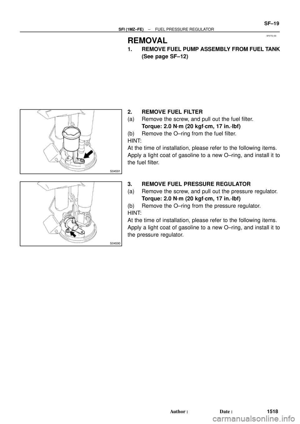
2. REMOVE FUEL FILTER
(a) Remove the screw, and pull out the fuel filter.
Torque: 2.0 N´m (20 kgf´cm, 17 in.´lbf)
(b) Remove the O±ring from the fuel filter.
HINT:
At the time of installation, please refer to the following items.
Apply a light coat of gasoline to a new O±ring, and install it to
the fuel filter.
3. REMOVE FUEL PRESSURE REGULATOR
(a) Remove the screw, and pull out the pressure regulator.
Torque: 2.0 N´m (20 kgf´cm, 17 in.´lbf)
(b) Remove the O±ring from the pressure regulator.
HINT:
At the time of installation, please refer to the following items.
Apply a light coat of gasoline to a new O±ring, and install it to
the pressure regulator.
Page 3408 of 4592
SF07H±01
SF±20
± SFI (1MZ±FE)FUEL PRESSURE REGULATOR
1519 Author�: Date�:
INSTALLATION
Installation is in the reverse order of removal. (See page SF±19)
Page 3411 of 4592
SF07K±04
S04505
S04498
S06086
Fuel Hose
Clamp
S05352
± SFI (1MZ±FE)INJECTOR
SF±23
1522 Author�: Date�:
REMOVAL
1. REMOVE AIR CLEANER HOSE
2. REMOVE AIR INTAKE CHAMBER ASSEMBLY
(See page EM±32)
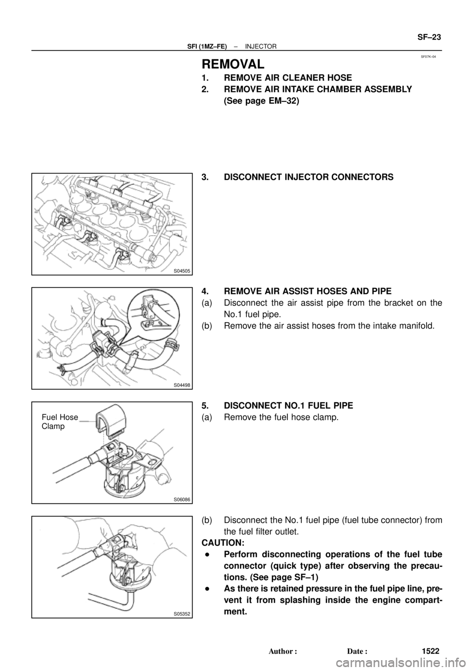
3. DISCONNECT INJECTOR CONNECTORS
4. REMOVE AIR ASSIST HOSES AND PIPE
(a) Disconnect the air assist pipe from the bracket on the
No.1 fuel pipe.
(b) Remove the air assist hoses from the intake manifold.
5. DISCONNECT NO.1 FUEL PIPE
(a) Remove the fuel hose clamp.
(b) Disconnect the No.1 fuel pipe (fuel tube connector) from
the fuel filter outlet.
CAUTION:
�Perform disconnecting operations of the fuel tube
connector (quick type) after observing the precau-
tions. (See page SF±1)
�As there is retained pressure in the fuel pipe line, pre-
vent it from splashing inside the engine compart-
ment.
Page 3415 of 4592

BatterySST
(Wire)
B00628
California A/TExcept
California A/T
± SFI (1MZ±FE)INJECTOR
SF±27
1526 Author�: Date�:
(k) Connect SST (wire)")
B01913
California A/T
Except California A/TBatterySST
(Wire)
BatterySST
(Wire)
B00628
California A/TExcept
California A/T
± SFI (1MZ±FE)INJECTOR
SF±27
1526 Author�: Date�:
(k) Connect SST (wire) to the injector and battery for 15 se-
conds, and measure the injection volume with a gra-
duated cylinder. Test each injector 2 or 3 times.
SST 09842±30070
Volume:
60 ± 73 cm
3 (3.4 ± 4.5 cu in.) per 15 sec.
Difference between each injector:
13 cm
3 (0.8 cu in.) or less
If the injection volume is not as specified, replace the injector.
2. INSPECT LEAKAGE
(a) In the condition above, disconnect the test probes of SST
(wire) from the battery and check the fuel leakage from
the injector.
SST 09842±30070
Fuel drop: 1 drop or less per 12 minutes
(b) Turn the ignition switch OFF.
(c) Disconnect the negative (±) terminal cable from the bat-
tery.
(d) Remove the SST and fuel tube connector.
SST 09268±41047, 09842±30070
CAUTION:
�Perform disconnecting operations of the fuel tube
connector (quick type) after observing the precau-
tions. (See page SF±1)
�As there is retained pressure in the fuel pipe line, pre-
vent it from splashing inside the engine compart-
ment.
(e) Disconnect the TOYOTA hand±held tester from the
DLC3.