Page 3338 of 4592
SF0DD±02
Z19026
Type A
Rear Seat Cushion
Floor Service Hole Cover
Fuel Pump & Sender
Gauge Connector
No.1 Fuel Tank Protector
Fuel Tank Vent Tube Set Plate
Fuel Pressure
Regulator
Fuel Filter Fuel Pump Assembly
� Gasket
N´m (kgf´cm, ft´lbf)� O±Ring � O±Ring
� Non±reusable part
4 (40, 35 in.´lbf)
: Specified torquex 8
SF±16
± SFI (5S±FE)FUEL PRESSURE REGULATOR
1449 Author�: Date�:
FUEL PRESSURE REGULATOR
COMPONENTS
Page 3339 of 4592
S06037
Type B
Rear Seat Cushion
Floor Service Hole Cover
Fuel Pump and Sender
Gauge Connector
No.1 Fuel Tank Protector
Fuel Tank Vent Tube Set Plate
Fuel Pressure
Regulator
Fuel Filter Fuel Pump Assembly
� Gasket
N´m (kgf´cm, ft´lbf)� O±Ring � O±Ring
� Non±reusable part
4 (40, 35 in.´lbf)
: Specified torquex 8
± SFI (5S±FE)FUEL PRESSURE REGULATOR
SF±17
1450 Author�: Date�:
Page 3340 of 4592
SF0DE±03
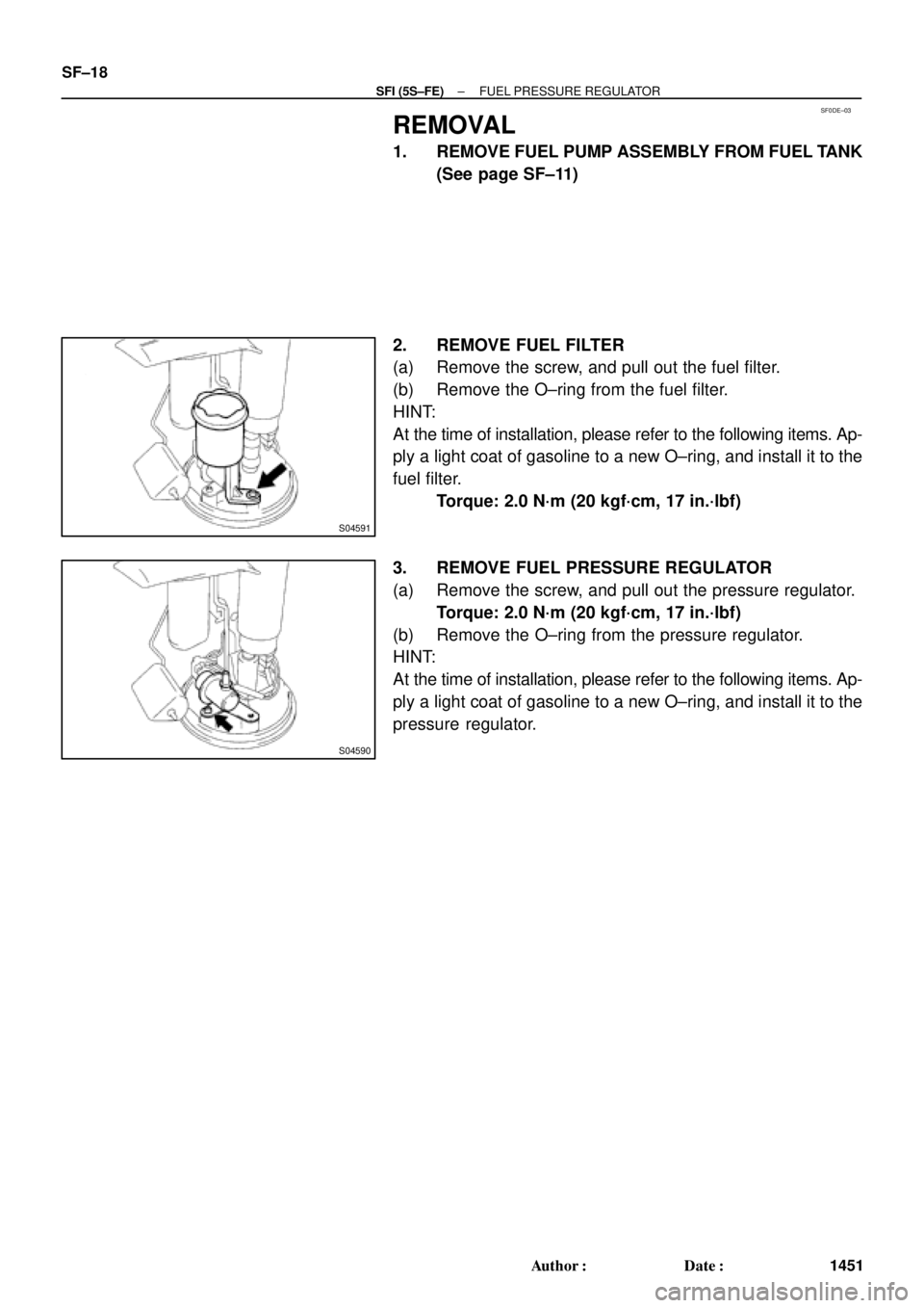
S04591
S04590
SF±18
± SFI (5S±FE)FUEL PRESSURE REGULATOR
1451 Author�: Date�:
REMOVAL
1. REMOVE FUEL PUMP ASSEMBLY FROM FUEL TANK
(See page SF±11)
2. REMOVE FUEL FILTER
(a) Remove the screw, and pull out the fuel filter.
(b) Remove the O±ring from the fuel filter.
HINT:
At the time of installation, please refer to the following items. Ap-
ply a light coat of gasoline to a new O±ring, and install it to the
fuel filter.
Torque: 2.0 N´m (20 kgf´cm, 17 in.´lbf)
3. REMOVE FUEL PRESSURE REGULATOR
(a) Remove the screw, and pull out the pressure regulator.
Torque: 2.0 N´m (20 kgf´cm, 17 in.´lbf)
(b) Remove the O±ring from the pressure regulator.
HINT:
At the time of installation, please refer to the following items. Ap-
ply a light coat of gasoline to a new O±ring, and install it to the
pressure regulator.
Page 3341 of 4592
SF0DF±01
± SFI (5S±FE)FUEL PRESSURE REGULATOR
SF±19
1452 Author�: Date�:
INSTALLATION
Installation is in the reverse order of removal. (See page SF±18)
Page 3390 of 4592
SFI SYSTEM
1501 Author�: Date�:
(b) When installing the battery, be especially careful not to in-
correctly connect the positive")
FI2553
SST
S04600
Fuel
Pump
Connector
S05039
Plug
SF±2
± SFI (1MZ±FE)SFI SYSTEM
1501 Author�: Date�:
(b) When installing the battery, be especially careful not to in-
correctly connect the positive (+) and negative (±) cables.
(c) Do not permit parts to receive a severe impact during re-
moval or installation. Handle all SFI parts carefully, espe-
cially the ECM.
(d) Be careful during troubleshooting as there are numerous
transistor circuit, and even slight terminal contact can
cause further troubles.
(e) Do not open the ECM cover.
(f) When inspecting during rainy weather, take care to pre-
vent entry of water. Also, when washing the engine
compartment, prevent water from getting on the SFI parts
and wiring connectors.
(g) Parts should be replaced as an assembly.
(h) Care should be taken when pulling out and inserting wir-
ing connectors.
(1) Release the lock and pull out the connector, pulling
on the connectors.
(2) Fully insert the connector and check that it is locked.
(i) Use SST for inspection or test of the injector or its wiring
connector.
SST 09842±30070
8. FUEL SYSTEM
(a) When disconnecting the high fuel pressure line, a large
amount of gasoline will spill out, so observe these proce-
dures:
(1) Disconnect the fuel pump connector.
(2) Start the engine. After the engine has stopped on
its own, turn the ignition switch to LOCK.
(3) Put a container under the connection.
(4) Slowly loosen the connection.
(5) Disconnect the connection.
(6) Plug the connection with a rubber plug.
Page 3391 of 4592
SFI SYSTEM
SF±3
1502 Author�: Date�:
(b) When connecting the union bolt on th")
S05054
New Gasket
FI1654
Fulcrum Length
30 cm
SST
FI6372 FI6372
New O±Ring
Grommet
InjectorCORRECT
WRONG
± SFI (1MZ±FE)SFI SYSTEM
SF±3
1502 Author�: Date�:
(b) When connecting the union bolt on the high pressure pipe
union, observe these procedures:
(1) Always use 2 new gaskets.
(2) Tighten the union bolt by hand.
(3) Tighten the union bolt to the specified torque.
Torque: 32.5 N´m (330 kgf´cm, 24 ft´lbf)
(c) When connecting the flare nut on the high pressure pipe
union, observe these procedures:
(1) Apply a light coat of engine oil to the flare nut, and
tighten the flare nut by hand.
(2) Using SST, tighten the flare nut to specified torque.
SST 09631±22020
NOTICE:
Do not rotate the fuel pipe, when tightening the flare nut.
Torque: 28 N´m (285 kgf´cm, 21 ft´lbf) for using SST
HINT:
Use a torque wrench with a fulcrum length of 30 cm (11.81 in.).
(d) Observe these precautions when removing and installing
the injectors.
(1) Never reuse the O±ring.
(2) When placing a new O±ring on the injector, take
care not to damage it in any way.
(3) Coat a new O±ring with spindle oil or gasoline be-
fore installing±never use engine, gear or brake oil.
Page 3394 of 4592
FUEL PUMP
1505 Author�: Date�:
FUEL PUMP
ON±VEHICLE INSPECTION
1. CHECK FUEL PUMP OPERATION
(a) Connect")
S05358
TOYOTA
Hand Held TesterSF079±04
S05353
S05359
Fuel Tube Connector
SF±6
± SFI (1MZ±FE)FUEL PUMP
1505 Author�: Date�:
FUEL PUMP
ON±VEHICLE INSPECTION
1. CHECK FUEL PUMP OPERATION
(a) Connect a TOYOTA hand±held tester to the DLC3.
(b) Turn the ignition switch ON and push the TOYOTA hand±
held tester main switch ON.
NOTICE:
Do not start the engine.
(c) Select the ACTIVE TEST mode on the TOYOTA hand±
held tester.
(d) Please refer to the TOYOTA hand±held tester operator's
manual for further details.
(e) If you have no TOYOTA hand±held tester, connect the
positive (+) and negative (±) leads from the battery to the
fuel pump connector. (See step 7)
(f) Check that there is pressure in the fuel inlet hose from the
fuel filter.
HINT:
If there is fuel pressure, you will hear the sound of fuel flowing.
If there is no pressure, check these parts:
Fusible link
Fuses
EFI main relay
Fuel pump
ECM
Wiring connections
(g) Turn the ignition switch OFF.
(h) Disconnect the TOYOTA hand±held tester from the
DLC3.
2. CHECK FUEL PRESSURE
(a) Check the battery positive voltage is above 12 V.
(b) Disconnect the negative (±) terminal cable from the bat-
tery.
(c) Purchase the new No.1 fuel pipe and take out the fuel
tube connector from its pipe.
Part No. 23801±20041
Page 3395 of 4592

Pipe
SST
(Hose)SST
± SFI (1MZ±FE)FUEL PUMP
SF±7
1506 Author�: Date�:
(d) Remove the fuel hose clamp.
(e) D")
S06086
Fuel Hose
Clamp
S05352
S05364
SST
SST
Retainer
No.1 Fuel
Fuel Tube
Connector (Hose)
Pipe
SST
(Hose)SST
± SFI (1MZ±FE)FUEL PUMP
SF±7
1506 Author�: Date�:
(d) Remove the fuel hose clamp.
(e) Disconnect the No.1 fuel pipe (fuel tube connector) from
the fuel filter outlet.
CAUTION:
�Perform disconnecting operations of the fuel tube
connector (quick type) after observing the precau-
tions. (See page SF±1)
�As there is retained pressure in the fuel pipe line, pre-
vent it from splashing inside the engine compart-
ment.
(f) Install SST (pressure gauge) as shown in the illustration
by using SST and fuel tube connector.
SST 09268±41047, 09268±41250, 09268±45012
(g) Wipe off any splattered gasoline.
(h) Reconnect the negative (±) terminal cable to the battery.
(i) Connect the TOYOTA hand held tester to the DLC3.
(See step 1. check fuel pump operation (a) to (e))
(j) Measure the fuel pressure.
Fuel pressure:
301 ± 347 kPa (3.1 ± 3.5 kgf/cm
2, 44 ± 50 psi)
If pressure is high, replace the fuel pressure regulator.
If pressure is low, check these parts:
Fuel hoses and connections
Fuel pump
Fuel filter
Fuel pressure regulator
(k) Disconnect the TOYOTA hand±held tester from the
DLC3.
(l) Start the engine.
(m) Measure the fuel pressure at idle.
Fuel pressure:
301 ± 347 kPa (3.1 ± 3.5 kgf/cm
2, 44 ± 50 psi)
(n) Stop the engine.
(o) Check that the fuel pressure remains as specified for 5
minutes after the engine has stopped.
Fuel pressure:
147 kPa (1.5 kgf/cm
2, 21 psi) or more
If pressure is not as specified, check the fuel pump, pressure
regulator and/or injectors.