Page 3508 of 4592

SR06C±01
SR±2
± STEERINGTROUBLESHOOTING
2097 Author�: Date�:
TROUBLESHOOTING
PROBLEM SYMPTOMS TABLE
Use the table below to help you find the cause of the problem. The numbers indicate the priority of the likely
cause of the problem. Check each part in the order shown. If necessary, repair or replace these parts.
SymptomSuspect AreaSee page
Hard steering
1. Tires (Improperly inflated)
2. Power steering fluid level (Low)
3. Drive belt (Loose)
4. Front wheel alignment (Incorrect)
5. Steering system joints (Worn)
6. Suspension arm ball joints (Worn)
7. Steering column (Binding)
8. Power steering vane pump
9. Power steering gearSA±2
SR±5
SR±3
SA±4
±
SA±45
±
SR±18
SR±31
Poor return
1. Tires (Improperly inflated)
2. Front wheel alignment (Incorrect)
3. Steering column (Binding)
4. Power steering gearSA±2
SA±4
±
SR±31
Excessive play
1. Steering system joints (Worn)
2. Suspension arm ball joints (Worn)
3. Intermediate shaft, Sliding yoke (Worn)
4. Front wheel bearing (Worn)
5. Power steering gear±
SA±45
±
SA±10
SR±31
Abnormal noise
1. Power steering fluid level (Low)
2. Steering system joints (Worn)
3. Power steering vane pump
4. Power steering gearSR±5
±
SR±18
SR±31
Page 3509 of 4592
 Visually check the belt for excessive w")
P06717
SR06D±01
Z00038
DENSO Borroughs
P06723
CORRECT WRONG WRONG
± STEERINGDRIVE BELT
SR±3
2098 Author�: Date�:
DRIVE BELT
INSPECTION
INSPECT DRIVE BELT
(a) Visually check the belt for excessive wear, frayed cords
etc.
If any defect has been found, replace the drive belt.
HINT:
Cracks on the rib side of a belt are considered acceptable. If the
belt has chunks missing from the ribs, it should be replaced.
(b) Using a belt tension gauge, measure the belt tension.
Belt tension gauge:
DENSO BTG±20 (95506±00020)
Borroughs No. BT±33±73F
5S±FE Engine:
Drive belt tension:
New belt: 95 ± 145 lbf
Used belt: 60 ± 100 lbf
1MZ±FE Engine:
Drive belt tension:
New belt: 150 ± 185 lbf
Used belt: 95 ± 135 lbf
If the belt tension is not as specified, adjust it.
HINT:
�ºNew beltº refers to a belt which has been used less than
5 minutes on a running engine.
�ºUsed beltº refers to a belt which has been used on a run-
ning engine for 5 minutes or more.
�After installing a belt, check that it fits properly in the
ribbed grooves.
�Check with your hand to confirm that the belt has not
slipped out of the groove on the bottom of the pulley.
�After installing a new belt, run the engine for about 5 min-
utes and recheck the belt tension.
Page 3510 of 4592
SR06E±01
R09599
Normal Abnormal SR±4
± STEERINGPOWER STEERING FLUID
2099 Author�: Date�:
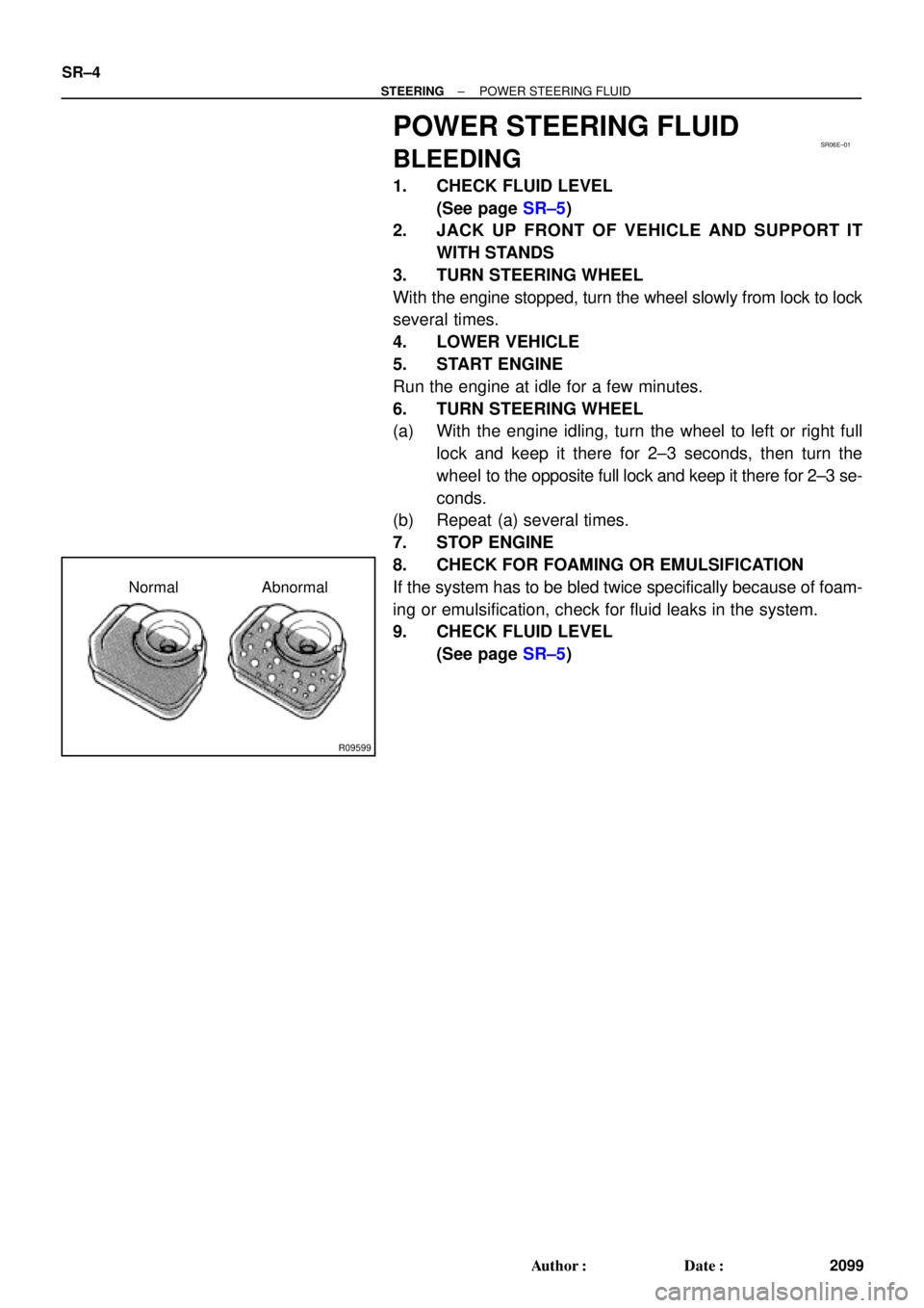
POWER STEERING FLUID
BLEEDING
1. CHECK FLUID LEVEL
(See page SR±5)
2. JACK UP FRONT OF VEHICLE AND SUPPORT IT
WITH STANDS
3. TURN STEERING WHEEL
With the engine stopped, turn the wheel slowly from lock to lock
several times.
4. LOWER VEHICLE
5. START ENGINE
Run the engine at idle for a few minutes.
6. TURN STEERING WHEEL
(a) With the engine idling, turn the wheel to left or right full
lock and keep it there for 2±3 seconds, then turn the
wheel to the opposite full lock and keep it there for 2±3 se-
conds.
(b) Repeat (a) several times.
7. STOP ENGINE
8. CHECK FOR FOAMING OR EMULSIFICATION
If the system has to be bled twice specifically because of foam-
ing or emulsification, check for fluid leaks in the system.
9. CHECK FLUID LEVEL
(See page SR±5)
Page 3511 of 4592

or less
Engine Idling Engine Stopped
± STEERINGPOWER STEERING FLUID
SR±5
2100 Author�: Date�:
INSPECTION
1. CHECK FLUID LEVEL
(a) Keep t")
SR06F±01
R00427
R09599
Normal Abnormal
R11562
5 mm (0.2 in.)
or less
Engine Idling Engine Stopped
± STEERINGPOWER STEERING FLUID
SR±5
2100 Author�: Date�:
INSPECTION
1. CHECK FLUID LEVEL
(a) Keep the vehicle level.
(b) With the engine stopped, check the fluid level in the oil
reservoir.
If necessary, add fluid.
Fluid: ATF DEXRON® II or III
HINT:
Check that the fluid level is within the HOT LEVEL range on the
reservoir. If the fluid is cold, check that it is within the COLD
LEVEL range.
(c) Start the engine and run it at idle.
(d) Turn the steering wheel from lock to lock several times to
boost fluid temperature.
Fluid temperature: 80°C (176°F)
(e) Check for foaming or emulsification.
If there is foaming or emulsification, bleed power steering
system.
(See page SR±4)
(f) With the engine idling, measure the fluid level in the oil
reservoir.
(g) Stop the engine.
(h) Wait a few minutes and remeasure the fluid level in the oil
reservoir.
Maximum fluid level rise: 5 mm (0.20 in.)
If a problem is found, bleed power steering system.
(See page SR±4)
(i) Check the fluid level.
Page 3512 of 4592
W03331
Attachment
Pressure Feed TubePressure Feed Tube SST
Out In 5S±FE Engine : 1MZ±FE Engine :
Out In
AttachmentAttachment Attachment
SST SR±6
± STEERINGPOWER STEERING FLUID
2101 Author�: Date�:
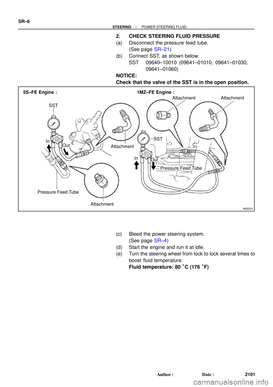
2. CHECK STEERING FLUID PRESSURE
(a) Disconnect the pressure feed tube.
(See page SR±21)
(b) Connect SST, as shown below.
SST 09640±10010 (09641±01010, 09641±01030,
09641±01060)
NOTICE:
Check that the valve of the SST is in the open position.
(c) Bleed the power steering system.
(See page SR±4)
(d) Start the engine and run it at idle.
(e) Turn the steering wheel from lock to lock several times to
boost fluid temperature.
Fluid temperature: 80 °C (176 °F)
Page 3513 of 4592

Z15498
Oil
PS Gear
Closed
SSTPS Vane
Pump Reservoir
Z15499
Oil
PS Gear
SSTPS Vane
Pump Reservoir
Open
Z15500
Oil
PS Gear
SSTPS Vane
Pump Reservoir
Lock Position
± STEERINGPOWER STEERING FLUID
SR±7
2102 Author�: Date�:
(f) With the engine idling, close the valve of the SST and ob-
serve the reading on the SST.
Minimum fluid pressure:
7,845 kPa (80 kgf´cm
2, 1,138 psi)
NOTICE:
�Do not keep the valve closed for more than 10 se-
conds.
�Do not let the fluid temperature become too high.
(g) With the engine idling, open the valve fully.
(h) Measure the fluid pressure at engine speeds of 1,000 rpm
and 3,000 rpm.
Difference fluid pressure:
490 kPa (5 kgf´cm
2, 71 psi) or less
NOTICE:
Do not turn the steering wheel.
(i) With the engine idling and valve fully opened, turn the
steering wheel to full lock.
Minimum fluid pressure:
7,845 kPa (80 kgf´cm
2, 1,138 psi)
NOTICE:
�Do not maintain lock position for more than 10 se-
conds.
�Do not let the fluid temperature become too high.
(j) Disconnect the SST.
(k) Connect the pressure feed tube.
(See page SR±28)
(l) Bleed the power steering system.
(See page SR±4)
Page 3514 of 4592
R07653
SR06G±01
F01477
SR±8
± STEERINGSTEERING WHEEL
2103 Author�: Date�:
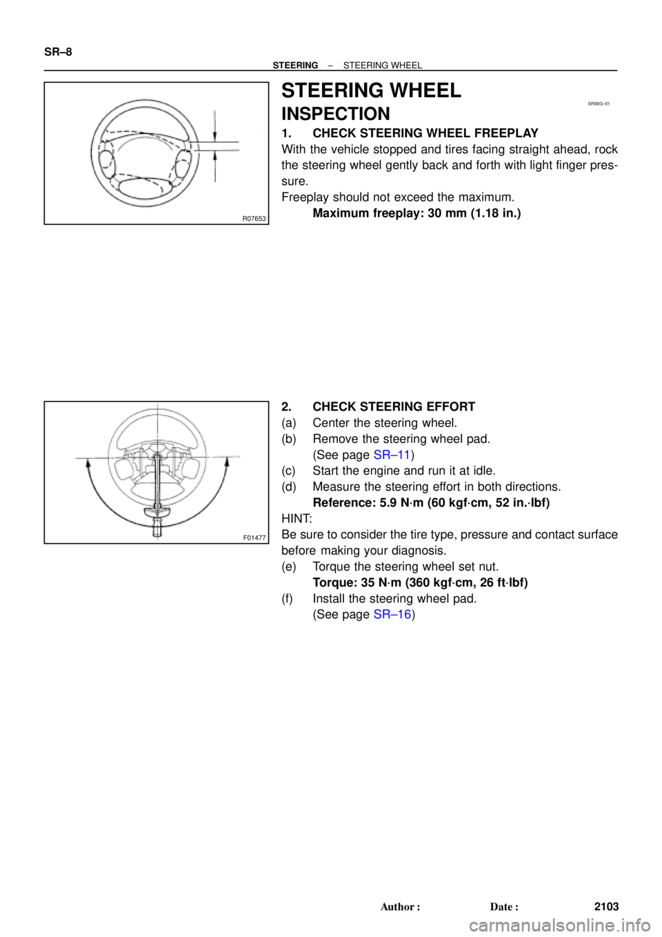
STEERING WHEEL
INSPECTION
1. CHECK STEERING WHEEL FREEPLAY
With the vehicle stopped and tires facing straight ahead, rock
the steering wheel gently back and forth with light finger pres-
sure.
Freeplay should not exceed the maximum.
Maximum freeplay: 30 mm (1.18 in.)
2. CHECK STEERING EFFORT
(a) Center the steering wheel.
(b) Remove the steering wheel pad.
(See page SR±11)
(c) Start the engine and run it at idle.
(d) Measure the steering effort in both directions.
Reference: 5.9 N´m (60 kgf´cm, 52 in.´lbf)
HINT:
Be sure to consider the tire type, pressure and contact surface
before making your diagnosis.
(e) Torque the steering wheel set nut.
Torque: 35 N´m (360 kgf´cm, 26 ft´lbf)
(f) Install the steering wheel pad.
(See page SR±16)
Page 3515 of 4592
SR06H±03
W03348
Torx ScrewSteering Wheel Pad
Steering Wheel
Torx Screw
Steering Wheel Lower
No.2 Cover
Steering Column Assembly
Intermediate Shaft Assembly
No.1 Lower Instrument Panel Combination Switch
(w/ Spiral Cable)Steering Wheel Lower
No.2 Cover
Column
Upper Cover
Lower No.2
Cover
Column Lower Cover
Lower Instrument
Finish Panel
Hood Lock Control Cable
Clip
Front Door Inside Scuff Plate
Cowl Side Trim LH Lower
Instrument Panel
35 (360, 26)
25 (260, 19)
7.1 (72, 63 in.´lbf)
35 (360, 26)
35 (360, 26)
7.1 (72, 63 in.´lbf)
N´m (kgf´cm, ft´lbf) : Specified torque
± STEERINGTILT STEERING COLUMN
SR±9
2104 Author�: Date�:
TILT STEERING COLUMN
COMPONENTS