Page 3154 of 4592

RS0ET±01
W03512
R09725Spiral Cable
W03511
H01347
H02610
RS±2
± SUPPLEMENTAL RESTRAINT SYSTEMSRS AIRBAG
2147 Author�: Date�:
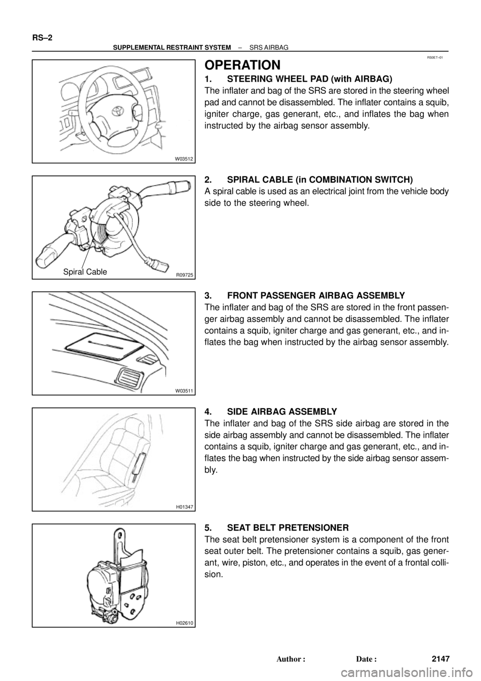
OPERATION
1. STEERING WHEEL PAD (with AIRBAG)
The inflater and bag of the SRS are stored in the steering wheel
pad and cannot be disassembled. The inflater contains a squib,
igniter charge, gas generant, etc., and inflates the bag when
instructed by the airbag sensor assembly.
2. SPIRAL CABLE (in COMBINATION SWITCH)
A spiral cable is used as an electrical joint from the vehicle body
side to the steering wheel.
3. FRONT PASSENGER AIRBAG ASSEMBLY
The inflater and bag of the SRS are stored in the front passen-
ger airbag assembly and cannot be disassembled. The inflater
contains a squib, igniter charge and gas generant, etc., and in-
flates the bag when instructed by the airbag sensor assembly.
4. SIDE AIRBAG ASSEMBLY
The inflater and bag of the SRS side airbag are stored in the
side airbag assembly and cannot be disassembled. The inflater
contains a squib, igniter charge and gas generant, etc., and in-
flates the bag when instructed by the side airbag sensor assem-
bly.
5. SEAT BELT PRETENSIONER
The seat belt pretensioner system is a component of the front
seat outer belt. The pretensioner contains a squib, gas gener-
ant, wire, piston, etc., and operates in the event of a frontal colli-
sion.
Page 3156 of 4592
H08316
Side Airbag Assembly (LH)
(Squib) Side Airbag Sensor (LH)Side Airbag Sensor (RH) Side Airbag Assembly (RH)
(Squib)
Seat Belt
Pretensioner (RH)
Airbag Sensor
AssemblyFront Passenger Airbag Assembly (Squib)
Spiral Cable
No.1 J/B 2
37 8
10
11
12
13
1
4
5
6
9
Steering Wheel
Pad (Squib) Front Airbag Sensor (RH)
Front Airbag Sensor (LH)
Seat Belt
Pretensioner (LH) 14
15
16
RS±4
± SUPPLEMENTAL RESTRAINT SYSTEMSRS AIRBAG
2149 Author�: Date�:
10. TMC made:
SRS CONNECTORS
No.ItemApplication
(1)Terminal Twin±Lock MechanismConnectors 1, 2, 3, 4, 5, 6, 7, 8, 9, 10, 11, 12, 13, 14, 15, 16
(2)Airbag Activation Prevention MechanismConnectors 1, 2, 3, 4, 5, 7, 8, 9, 15, 16
(3)Electrical Connection Check MechanismConnectors 1, 2, 3
(4)Connector Twin±Lock MechanismConnectors 5, 6, 7
Page 3157 of 4592
H08247
Airbag Sensor
Assembly2
31
Side Airbag Assembly (RH)
(Squib)
Seat Belt
Pretensioner (RH)
Side Airbag Sensor (RH)
Front Passenger Airbag
Assembly (Squib)
Spiral Cable
Steering Wheel
Pad (Squib)
No.1 J / B
Side Airbag Sensor (LH)
Side Airbag Assembly (LH)
(Squib)
4
5
6
7
14
9
10
1112
13
8
15
Seat Belt
Pretensioner (LH)
16
17
18
Front Airbag Sensor (RH)
Front Airbag Sensor (LH)
± SUPPLEMENTAL RESTRAINT SYSTEMSRS AIRBAG
RS±5
2150 Author�: Date�:
11. TMMK made:
SRS CONNECTORS
No.ItemApplication
(1)Terminal Twin±Lock MechanismConnectors 1, 2, 3, 4, 5, 6, 7, 8, 9, 10, 11, 12, 13, 14, 15, 16,
17, 18
(2)Airbag Activation Prevention MechanismConnectors 1, 2, 3, 4, 5, 7, 8, 9, 15, 16, 17, 18
(3)Electrical Connection Check MechanismConnectors 1, 2, 3
(4)Connector Twin±Lock MechanismConnectors 5, 6, 7
Page 3160 of 4592

AB0089
Secondary Lock
Primary LockLockLock
Primary Lock Incomplete
(Secondary Lock Prevented)Primary Lock Complete
(Secondary Lock Permitted)Twin±Lock Completed
Z14034
Fig.1
Fig.2Power Source
Safing
Sensor
Squibs
Deceleration
Sensor RS±8
± SUPPLEMENTAL RESTRAINT SYSTEMSRS AIRBAG
2153 Author�: Date�:
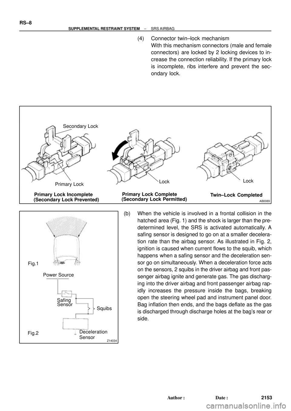
(4) Connector twin±lock mechanism
With this mechanism connectors (male and female
connectors) are locked by 2 locking devices to in-
crease the connection reliability. If the primary lock
is incomplete, ribs interfere and prevent the sec-
ondary lock.
(b) When the vehicle is involved in a frontal collision in the
hatched area (Fig. 1) and the shock is larger than the pre-
determined level, the SRS is activated automatically. A
safing sensor is designed to go on at a smaller decelera-
tion rate than the airbag sensor. As illustrated in Fig. 2,
ignition is caused when current flows to the squib, which
happens when a safing sensor and the deceleration sen-
sor go on simultaneously. When a deceleration force acts
on the sensors, 2 squibs in the driver airbag and front pas-
senger airbag ignite and generate gas. The gas discharg-
ing into the driver airbag and front passenger airbag rap-
idly increases the pressure inside the bags, breaking
open the steering wheel pad and instrument panel door.
Bag inflation then ends, and the bags deflate as the gas
is discharged through discharge holes at the bag's rear or
side.
Page 3166 of 4592
RS00Y±20
H03294
Column Upper Cover
Spiral CableSteering Wheel
Steering Wheel Pad
Column Lower Cover
N´m (kgf´cm, ft´lbf) : Specified torque
7.1 (72, 63 in.´lbf)
35 (360, 26)
Steering Wheel Lower
No.2 Cover
Steering Wheel Lower
No.2 Cover
Torx Screw
RS±14
± SUPPLEMENTAL RESTRAINT SYSTEMSTEERING WHEEL PAD AND SPIRAL CABLE
2159 Author�: Date�:
STEERING WHEEL PAD AND SPIRAL CABLE
COMPONENTS
Page 3167 of 4592
RS00Z±14
± SUPPLEMENTAL RESTRAINT SYSTEMSTEERING WHEEL PAD AND SPIRAL CABLE
RS±15
2160 Author�: Date�:
REMOVAL
HINT:
For step 1 to 4, refer to page SR±11.
1. REMOVE STEERING WHEEL PAD
2. REMOVE STEERING WHEEL
3. REMOVE UPPER AND LOWER COLUMN COVERS
4. REMOVE SPIRAL CABLE
Page 3168 of 4592

RS010±19
W03512
W03513
W03521
Horn Button
Contact Plate
RS±16
± SUPPLEMENTAL RESTRAINT SYSTEMSTEERING WHEEL PAD AND SPIRAL CABLE
2161 Author�: Date�:
INSPECTION
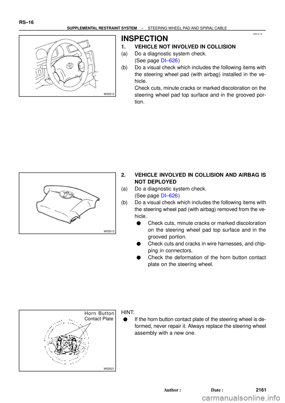
1. VEHICLE NOT INVOLVED IN COLLISION
(a) Do a diagnostic system check.
(See page DI±626)
(b) Do a visual check which includes the following items with
the steering wheel pad (with airbag) installed in the ve-
hicle.
Check cuts, minute cracks or marked discoloration on the
steering wheel pad top surface and in the grooved por-
tion.
2. VEHICLE INVOLVED IN COLLISION AND AIRBAG IS
NOT DEPLOYED
(a) Do a diagnostic system check.
(See page DI±626)
(b) Do a visual check which includes the following items with
the steering wheel pad (with airbag) removed from the ve-
hicle.
�Check cuts, minute cracks or marked discoloration
on the steering wheel pad top surface and in the
grooved portion.
�Check cuts and cracks in wire harnesses, and chip-
ping in connectors.
�Check the deformation of the horn button contact
plate on the steering wheel.
HINT:
�If the horn button contact plate of the steering wheel is de-
formed, never repair it. Always replace the steering wheel
assembly with a new one.
Page 3169 of 4592

W03651
± SUPPLEMENTAL RESTRAINT SYSTEMSTEERING WHEEL PAD AND SPIRAL CABLE
RS±17
2162 Author�: Date�: �
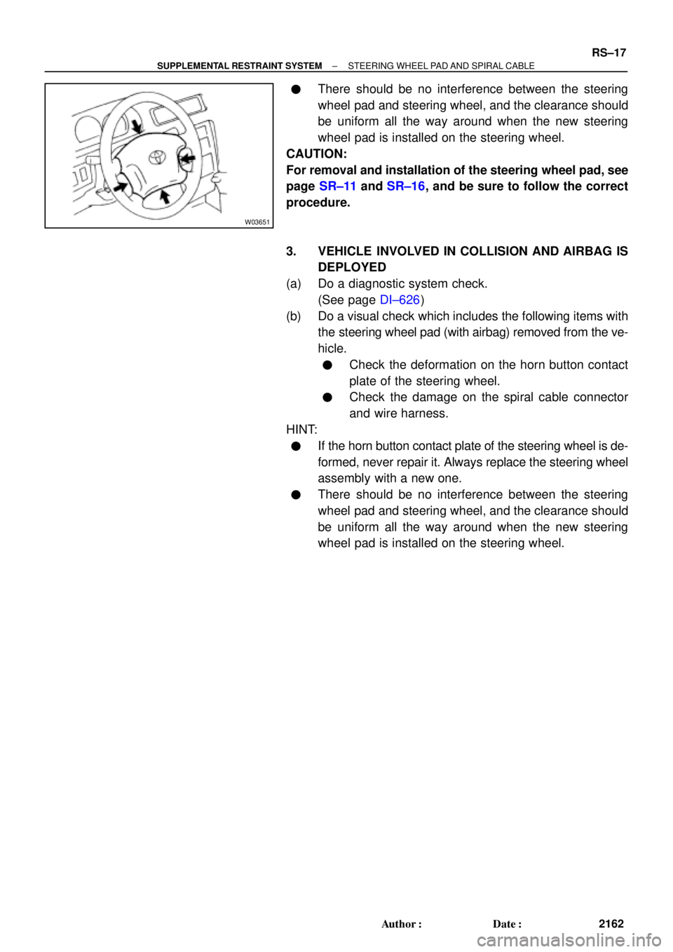
There should be no interference between the steering
wheel pad and steering wheel, and the clearance should
be uniform all the way around when the new steering
wheel pad is installed on the steering wheel.
CAUTION:
For removal and installation of the steering wheel pad, see
page SR±11 and SR±16, and be sure to follow the correct
procedure.
3. VEHICLE INVOLVED IN COLLISION AND AIRBAG IS
DEPLOYED
(a) Do a diagnostic system check.
(See page DI±626)
(b) Do a visual check which includes the following items with
the steering wheel pad (with airbag) removed from the ve-
hicle.
�Check the deformation on the horn button contact
plate of the steering wheel.
�Check the damage on the spiral cable connector
and wire harness.
HINT:
�If the horn button contact plate of the steering wheel is de-
formed, never repair it. Always replace the steering wheel
assembly with a new one.
�There should be no interference between the steering
wheel pad and steering wheel, and the clearance should
be uniform all the way around when the new steering
wheel pad is installed on the steering wheel.