Page 2244 of 4592

A09424
ON
VCNG2
(±)
(+) E01
A09425
ON
VCNG3
(±)(+) E01
± DIAGNOSTICSENGINE
DI±93
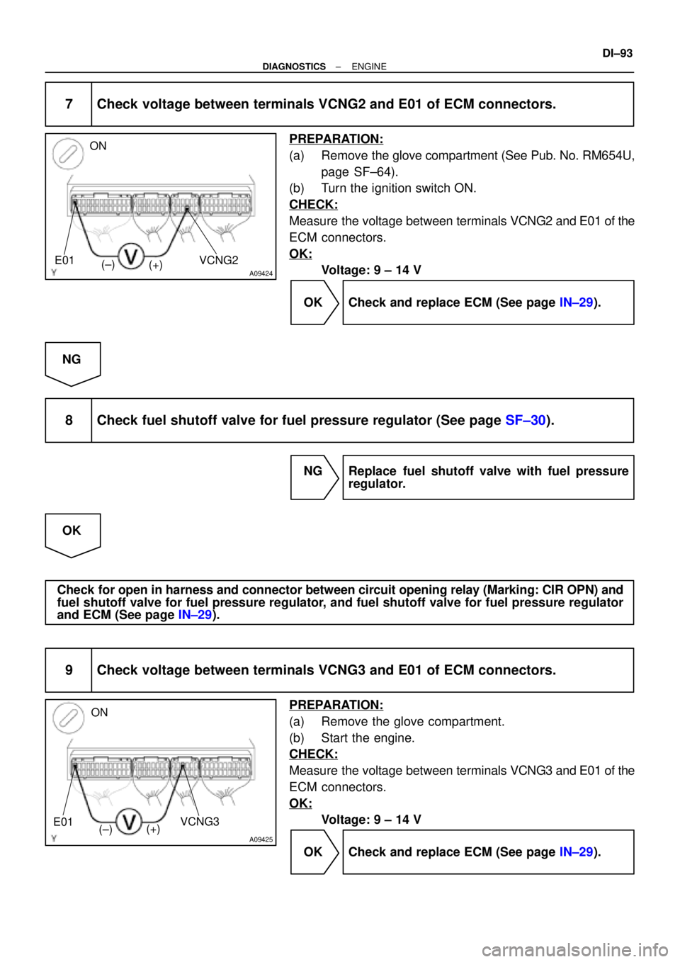
7 Check voltage between terminals VCNG2 and E01 of ECM connectors.
PREPARATION:
(a) Remove the glove compartment (See Pub. No. RM654U,
page SF±64).
(b) Turn the ignition switch ON.
CHECK:
Measure the voltage between terminals VCNG2 and E01 of the
ECM connectors.
OK:
Voltage: 9 ± 14 V
OK Check and replace ECM (See page IN±29).
NG
8 Check fuel shutoff valve for fuel pressure regulator (See page SF±30).
NG Replace fuel shutoff valve with fuel pressure
regulator.
OK
Check for open in harness and connector between circuit opening relay (Marking: CIR OPN) and
fuel shutoff valve for fuel pressure regulator, and fuel shutoff valve for fuel pressure regulator
and ECM (See page IN±29).
9 Check voltage between terminals VCNG3 and E01 of ECM connectors.
PREPARATION:
(a) Remove the glove compartment.
(b) Start the engine.
CHECK:
Measure the voltage between terminals VCNG3 and E01 of the
ECM connectors.
OK:
Voltage: 9 ± 14 V
OK Check and replace ECM (See page IN±29).
Page 2249 of 4592

DI±98
± DIAGNOSTICSENGINE
DTC P1245 Fuel Fuel Shutoff Valve Circuit for Pressure
Regulator Malfunction
CIRCUIT DESCRIPTION
Refer to DTC P1190 on page DI±86.
DTC No.DTC Detecting ConditionTrouble Area
P1245Open in fuel shutoff valve circuit for fuel pressure regulator
�Open or short in fuel shutoff valve circuit for fuel pressure
regulator
�Fuel shutoff valve for fuel pressure regulator
�ECM
WIRING DIAGRAM
Refer to DTC P1190 on page DI±86.
INSPECTION PROCEDURE
TOYOTA hand±held tester:
1 Check fuel shutoff valve circuit for fuel pressure regulator.
PREPARATION:
(a) Connect the TOYOTA hand±held tester to the DLC3.
(b) Turn the ignition switch ON and push the TOYOTA hand±held tester main switch ON.
(c) Select the ACTIVE TEST mode on the TOYOTA hand±held tester.
CHECK:
Check the operating sound of the fuel shutoff valve for the pressure regulator when it is operated by the TOY-
OTA hand±held tester.
HINT:
Use a sound scope or your finger to check the operating sound.
OK:
There is operating sound from the shutoff valve.
OK Go to step 4.
NG
2 Check for ECM power source circuit (See page DI±116).
NG Repair or replace.
OK
DI64Z±01
Page 2251 of 4592

A09277
FC ON
(±) (+)
DI±100
± DIAGNOSTICSENGINE
6 Check fuel shutoff valve for fuel pressure regulator (See page SF±30).
NG Replace fuel shutoff valve for fuel pressure reg-
ulator.
OK
Check for open in harness and connector between circuit opening relay (Marking: CIR OPN) and
fuel shutoff valve for fuel pressure regulator, and fuel shutoff valve for fuel pressure regulator
and ECM (See page IN±29).
OBD II scan tool (excluding TOYOTA hand±held tester):
1 Check for ECM power source circuit (See page DI±116).
NG Repair or replace.
OK
2 Check fuel shutoff valve for fuel pressure regulator (See page SF±30).
NG Replace circuit opening relay.
OK
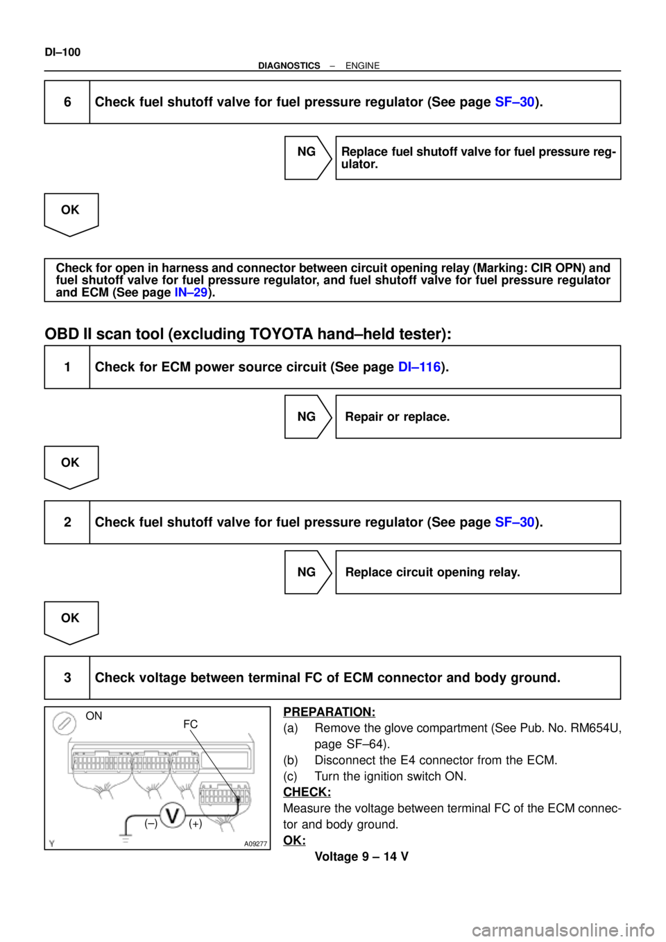
3 Check voltage between terminal FC of ECM connector and body ground.
PREPARATION:
(a) Remove the glove compartment (See Pub. No. RM654U,
page SF±64).
(b) Disconnect the E4 connector from the ECM.
(c) Turn the ignition switch ON.
CHECK:
Measure the voltage between terminal FC of the ECM connec-
tor and body ground.
OK:
Voltage 9 ± 14 V
Page 2252 of 4592
A09424
ON
VCNG2
(±)
(+) E01
± DIAGNOSTICSENGINE
DI±101
OK Go to step 4.
NG
Check for open in harness and connector between EFI main relay (Marking: EFI) and circuit open-
ing relay (Marking: CIR OPN), and circuit opening relay and ECM (See page IN±29).
4 Check voltage between terminals VCNG2 and E01 of ECM connectors.
PREPARATION:
(a) Remove the glove compartment (See Pub. No. RM654U,
page SF±64).
(b) Turn the ignition switch ON.
CHECK:
Measure the voltage between terminals VCNG2 and E01 of the
ECM connectors.
OK:
Voltage 9 ± 14 V
OK Check and replace ECM (See page IN±29).
NG
5 Check fuel shutoff valve for fuel pressure regulator (See page SF±30).
NG Replace fuel shutoff valve for fuel pressure reg-
ulator.
OK
Check for open in harness and connector between circuit opening relay (Marking: CIR OPN) and
fuel shutoff valve for fuel pressure regulator, and fuel shutoff valve for fuel pressure regulator
and ECM (See page IN±29).
Page 2275 of 4592
A00309
ECM Fuel Pressure Sensor
for Fuel Pipe
1PCNG1VC
E2 Y
G±RE5
E7
E5 3
25 V
E1 1
5
9
BR
BE6653A03008A09254
ON
E2VC
(±) (+)
± DIAGNOSTICSENGINE
DI±123
Fuel Pressure Sensor Circuit for Fuel Pipe
CIRCUIT DESCRIPTION
Refer to DTC P0190 on page DI±56.
WIRING DIAGRAM
INSPECTION PROCEDURE
1 Check voltage between terminals VC and E2 of ECM connector.
PREPARATION:
(a) Remove the glove compartment (See Pub. No. RM654U,
page SF±64).
(b) Turn the ignition switch ON.
CHECK:
Measure the voltage between terminals VC and E2 of the ECM
connector.
OK:
Voltage: 4.5 ± 5.5 V
NG Check and replace ECM (See page IN±29).
OK
DI650±01
Page 2276 of 4592
BE6653A09292A09419
E2 ONPCNG1
(±)
(+)
DI±124
± DIAGNOSTICSENGINE
2 Check voltage between terminals PCNG1 and E2 of ECM connector.
PREPARATION:
(a) Remove the glove compartment (See Pub. No. RM654U,
page SF±64).
(b) Turn the ignition switch ON.
CHECK:
Measure the voltage between terminals PCNG1 and E2 of the
ECM connector.
OK:
Needle position of fuel level gaugeVoltage (V) at 20°C (68°F)
4/43.3
3/42.7
2/42.0
1/41.3
OK Check and replace ECM (See page IN±29).
NG
3 Check for open and short in harness and connector between fuel pressure sen-
sor for fuel pipe and ECM
(See page IN±29).
NG Repair or replace harness or connector.
OK
Replace fuel pressure sensor for fuel pipe
(See page SF±46).
Page 2277 of 4592

A09421
E7
E51
9ECM
5 V
THCNG1
E2
E1 R
BR 3
4
BR Fuel Temperature
Sensor for Fuel Tank
BR IB1
IG2 LG±B
IB1IG2 LG±B LG±B 42
3 2
A09294BE6653
A09393
ON
THCNG1 E2
(±) (+)
± DIAGNOSTICSENGINE
DI±125
Fuel Temperature Sensor Circuit for Fuel Tank
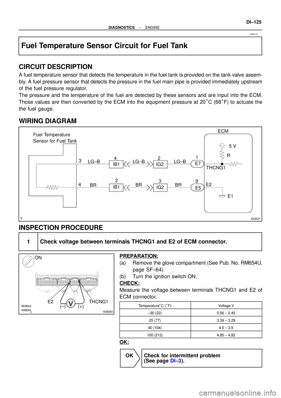
CIRCUIT DESCRIPTION
A fuel temperature sensor that detects the temperature in the fuel tank is provided on the tank valve assem-
bly. A fuel pressure sensor that detects the pressure in the fuel main pipe is provided immediately upstream
of the fuel pressure regulator.
The pressure and the temperature of the fuel are detected by these sensors and are input into the ECM.
Those values are then converted by the ECM into the equipment pressure at 20°C (68°F) to actuate the
the fuel gauge.
WIRING DIAGRAM
INSPECTION PROCEDURE
1 Check voltage between terminals THCNG1 and E2 of ECM connector.
PREPARATION:
(a) Remove the glove compartment (See Pub. No. RM654U,
page SF±64).
(b) Turn the ignition switch ON.
CHECK:
Measure the voltage between terminals THCNG1 and E2 of
ECM connector.
Temperature°C (°F)Voltage V
±30 (22)0.56 ± 0.45
25 (77)3.39 ± 3.29
40 (104)4.0 ± 3.9
100 (212)4.85 ± 4.82
OK:
OK Check for intermittent problem
(See page DI±3).
DI652±01
Page 2278 of 4592
DI±126
± DIAGNOSTICSENGINE
NG
2 Check fuel pressure sensor for fuel tank (See page SF±40).
NG Replace fuel pressure sensor for fuel tank.
OK
3 Check for open and short in harness and connector brtween ECM and fuel pres-
sure sensor for fuel tank (See page IN±29).
NG Repair or replace harness or connector.
OK
Check and replace ECM (See page IN±29).