Page 2207 of 4592

A00309
ECM Fuel Pressure Sensor
for Delivery Pipe
1PCNG2VC
E2 Y
G±BE5
E7
E5 3
25 V
E1 1
5
9
BR DI±56
± DIAGNOSTICSENGINE
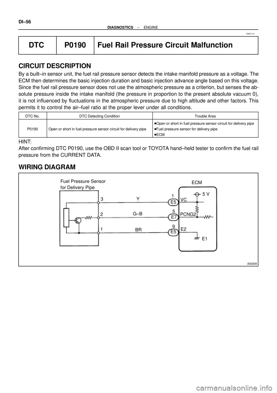
DTC P0190 Fuel Rail Pressure Circuit Malfunction
CIRCUIT DESCRIPTION
By a built±in sensor unit, the fuel rail pressure sensor detects the intake manifold pressure as a voltage. The
ECM then determines the basic injection duration and basic injection advance angle based on this voltage.
Since the fuel rail pressure sensor does not use the atmospheric pressure as a criterion, but senses the ab-
solute pressure inside the intake manifold (the pressure in proportion to the present absolute vacuum 0),
it is not influenced by fluctuations in the atmospheric pressure due to high altitude and other factors. This
permits it to control the air±fuel ratio at the proper lever under all conditions.
DTC No.DTC Detecting ConditionTrouble Area
P0190Open or short in fuel pressure sensor circuit for delivery pipe
�Open or short in fuel pressure sensor circuit for delivery pipe
�Fuel pressure sensor for delivery pipe
�ECM
HINT:
After confirming DTC P0190, use the OBD II scan tool or TOYOTA hand±held tester to confirm the fuel rail
pressure from the CURRENT DATA.
WIRING DIAGRAM
DI64V±01
Page 2208 of 4592

BE6653A03008A09254
ON
E2VC
(±)
(+)
A09293BE6653A09297
E2 ONPCNG2
(±) (+)
± DIAGNOSTICSENGINE
DI±57
INSPECTION PROCEDURE
HINT:
If DTC P0105, P0106, P0110, P0115, P0120, P0180 and P0190 are output simultaneously, E2 (sensor
ground) may be open.
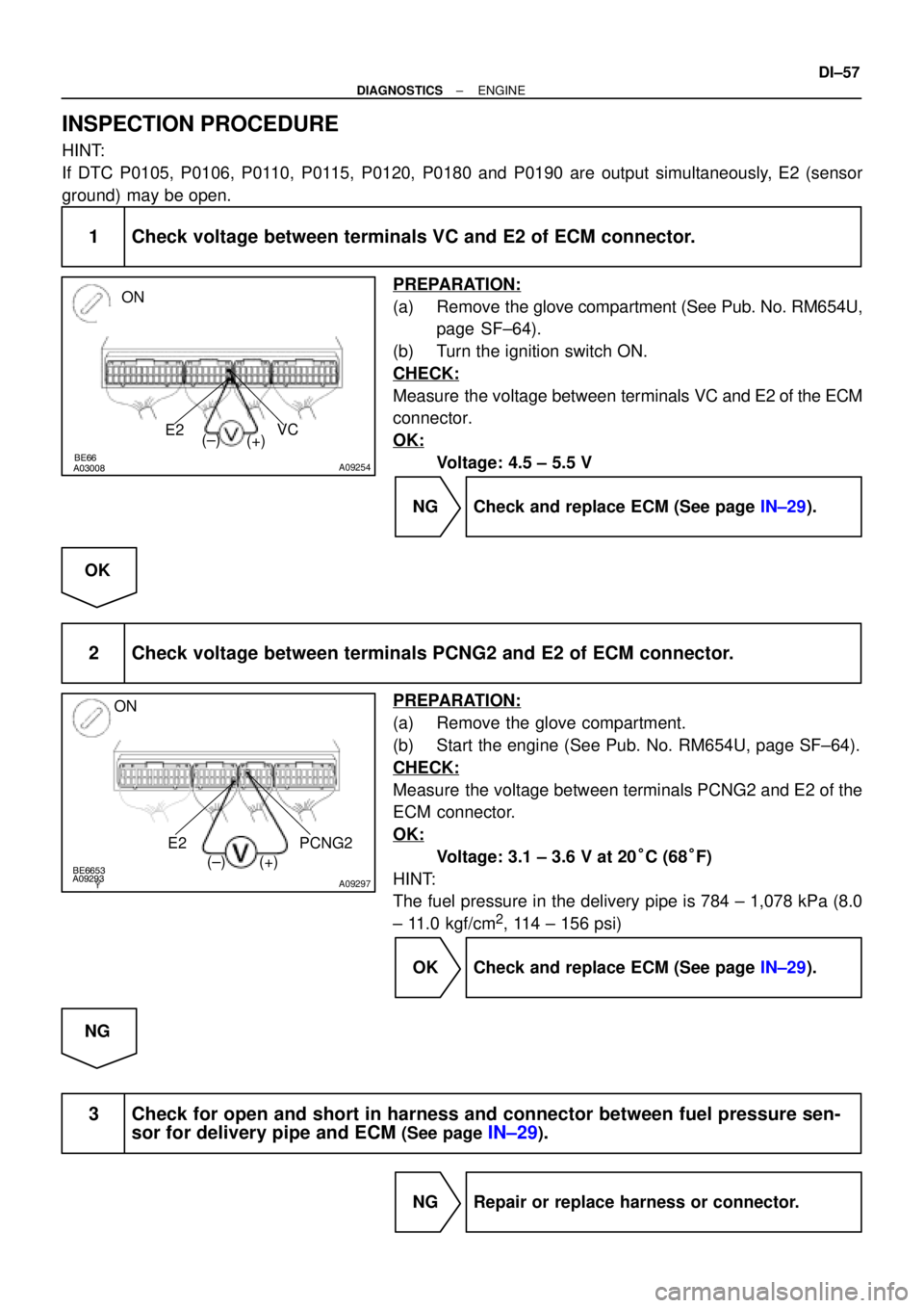
1 Check voltage between terminals VC and E2 of ECM connector.
PREPARATION:
(a) Remove the glove compartment (See Pub. No. RM654U,
page SF±64).
(b) Turn the ignition switch ON.
CHECK:
Measure the voltage between terminals VC and E2 of the ECM
connector.
OK:
Voltage: 4.5 ± 5.5 V
NG Check and replace ECM (See page IN±29).
OK
2 Check voltage between terminals PCNG2 and E2 of ECM connector.
PREPARATION:
(a) Remove the glove compartment.
(b) Start the engine (See Pub. No. RM654U, page SF±64).
CHECK:
Measure the voltage between terminals PCNG2 and E2 of the
ECM connector.
OK:
Voltage: 3.1 ± 3.6 V at 20°C (68°F)
HINT:
The fuel pressure in the delivery pipe is 784 ± 1,078 kPa (8.0
± 11.0 kgf/cm
2, 114 ± 156 psi)
OK Check and replace ECM (See page IN±29).
NG
3 Check for open and short in harness and connector between fuel pressure sen-
sor for delivery pipe and ECM
(See page IN±29).
NG Repair or replace harness or connector.
Page 2209 of 4592
DI±58
± DIAGNOSTICSENGINE
OK
Replace fuel pressure sensor for delivery
pipe (See page SF±43).
Page 2230 of 4592

A00364
Vehicle Speed
60 ± 120 km/h
(38 ± 75 mph)
Idling
IG SW OFF
3 ± 5 min.
Time
(1)(2)(4)
(3)
± DIAGNOSTICSENGINE
DI±79
DTC P1130 A/F Sensor Circuit Range/Performance Mal-
function (Bank 1 Sensor 1)
CIRCUIT DESCRIPTION
Refer to DTC P0125 on page DI±40.
DTC No.DTC Detecting ConditionTrouble Area
Voltage output* of A/F sensor remains at 4.5 V or more, during
engine running after engine is warmed up (2 trip detection log-
ic)
*: Output value changes at the inside of ECM only
�Open or short in A/F sensor circuit
�A/F sensor
�
Air induction system
P1130Voltage output* of A/F sensor does not change from 3.30 V,
during engine running after engine is warmed up (2 trip detec-
tion logic)
*: Output value changes at inside of ECM only
�Air induction system
�EGR system
�Fuel pressure
�Injector
�ECM
Open or short in A/F sensor circuit (2 trip detection logic)
HINT:
�After confirming DTC P1130, use the OBD II scan tool or TOYOTA hand-held tester to confirm voltage
output of the A/F sensor (AFS B1 S1/O2S B1 S1) from the CURRENT DATA.
�The A/F sensor's output voltage and the short-term fuel trim value can be read using the OBD II scan
tool or TOYOTA hand-held tester.
�The ECM controls the voltage of the AF+ and AF± terminals of the ECM to the fixed voltage. Therefore,
it is impossible to confirm the A/F sensor output voltage without OBD II scan tool or TOYOTA hand±
held tester.
�OBD II scan tool (excluding TOYOTA hand-held tester) displays the one fifth of the A/F sensor output
voltage which is displayed on the TOYOTA hand-held tester.
WIRING DIAGRAM
Refer to DTC P0125 on page DI±40.
CONFIRMATION DRIVING PATTERN
DI01D±08
Page 2237 of 4592

DI±86
± DIAGNOSTICSENGINE
DTC P1190 Fuel Pressure Regulator Malfunction
CIRCUIT DESCRIPTION
The fuel pressure regulator regulates the fuel pressure by reducing the pressure of the compressed fuel from
the fuel tank to the fuel injection pressure, which is 785 kPa (8 kgf/cm
2, 114 psi).
Similar to the fuel shutoff valve for the fuel tank, a fuel shutoff valve is provided on the fuel inlet side of the
fuel pressure regulator to shutoff the supply of fuel when the engine is stopped or during abnormal condi-
tions.
A reservoir that traps the moisture and oil in the fuel is provided on the low pressure side.
A built±in relief valve is provided to protect the parts located on the low pressure side.
While the fuel pressure is being reduced by the fuel pressure regulator, the Joule±Thompson effect
associated with the expansion of the fuel causes the fuel pressure regulator to be cooled excessively, exert-
ing unfavorable influence on the rubber parts such as diaphragms and fuel hoses.
Therefore, to raise the fuel temperature, a water passage is provided in the fuel pressure regulator to allow
the engine coolant to warm the regulator.
DTC No.DTC Detecting ConditionTrouble Area
P1190After engine is warmed up, detection of pressure control
malfunction (2 trip detection logic)
�Open or short in fuel shutoff valve circuit for fuel tank
�Fuel shutoff valve for fuel tank
�Open or short in fuel shutoff valve circuit for fuel pressure
regulator
�Fuel shutoff valve for fuel pressure regulator
�Fuel fuel pressure regulator
�Open or short in fuel shutoff valve circuit for fuel delivery
pipe
�Fuel shutoff valve for fuel delivery pipe
�ECM
DI64X±01
Page 2238 of 4592
A09426
Battery
EFI
AM2
1 2 3
3 1J
B2A
2J Instrument Panel J/B
1B 1W
37
15
IG Switch
1
B±RST Relay EFI Relay
5
6 3
11 410
4
5 4
5
A 2B STARTER
II23
B±W
II2
11
Starter
Park/Neutral
Position Switch
5 7
B±R Engine Room J/B No.2
2C
2F IGN
FL Block1
2D1
MAIN
W±B
10B
C
1
CIR
OPN
Relay
IGG±R
14
2L
E4FCECM
E01 1
S1S2
Engine Room R/B
No.1
2
J40
J/C
G±R
L±B
5 93
L±B
R
EB B±R
GR
W±R
B±W
BL
J/CB±R
J8
2K
J7
B
1 1 1
B 1K
1K
1K
8 76
EB1
4
J11
J/CF6 1
W±R
MAIN
FL2K
2
B±RB
B F41
GR
A
EB1
55
W±BW±B
GR
Fuel ShutOff Valve For
Pressure Regulator
Fuel ShutOff Valve
For Fuel TankFuel ShutOff Valve
For Delivery Pipe
ID1
7 J29
J/C
B
B±W
VCNG2VCNG3 4
E7
9
E7
13
E6 2
2J21
II39
II4
6 J19
J/C
B
B±G
21
21
L±B L±B
EC
L±B L±B
Y±G
W±B B±Y B±Y
BB±Y
P
± DIAGNOSTICSENGINE
DI±87
WIRING DIAGRAM
Page 2239 of 4592

DI±88
± DIAGNOSTICSENGINE
INSPECTION PROCEDURE
TOYOTA hand±held tester:
1 Check fuel shutoff valve for delivery pipe.
PREPARATION:
(a) Connect the TOYOTA hand±held tester to the DLC3.
(b) Turn the ignition switch ON and push the TOYOTA hand±held tester main switch ON.
(c) Select the ACTIVE TEST mode on the TOYOTA hand±held tester.
CHECK:
Check the operating sound of the fuel shutoff valve for delivery pipe for fuel tank when it is operated by the
TOYOTA hand±held tester.
HINT:
Use a sound scope or your finger to check the operating sound.
OK:
There is operating sound from the shutoff valve.
OK Go to step 9.
2 Check fuel shutoff valve for fuel pressure regulator and fuel shutoff valve for
fuel tank.
PREPARATION:
(a) Connect the TOYOTA hand±held tester to the DLC3.
(b) Turn the ignition switch ON and push the TOYOTA hand±held tester main switch ON.
(c) Select the ACTIVE TEST mode on the TOYOTA hand±held tester.
CHECK:
Check the operating sound of the fuel shutoff valve for fuel pressure regulator and fuel shutoff valve for fuel
tank when it is operated by the TOYOTA hand±held tester.
HINT:
Fuel shutoff valve for fuel pressure regulator:
Use a sound scope or your finger to check the operating sound.
OK:
There is operating sound from the shutoff valve.
NG Fuel shutoff valve for fuel pressure regulator ...
Go to step 7.
NG Fuel shutoff valve for fuel tank ... Go to step 4.
NG
Page 2241 of 4592

A09424
ON
VCNG2
(±)
(+) E01
A09425
ON
VCNG3
(±)(+) E01
DI±90
± DIAGNOSTICSENGINE
OK
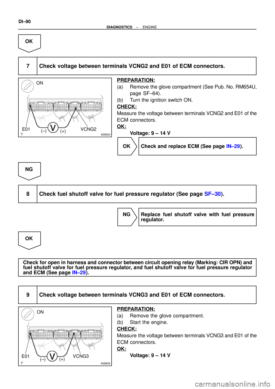
7 Check voltage between terminals VCNG2 and E01 of ECM connectors.
PREPARATION:
(a) Remove the glove compartment (See Pub. No. RM654U,
page SF±64).
(b) Turn the ignition switch ON.
CHECK:
Measure the voltage between terminals VCNG2 and E01 of the
ECM connectors.
OK:
Voltage: 9 ± 14 V
OK Check and replace ECM (See page IN±29).
NG
8 Check fuel shutoff valve for fuel pressure regulator (See page SF±30).
NG Replace fuel shutoff valve with fuel pressure
regulator.
OK
Check for open in harness and connector between circuit opening relay (Marking: CIR OPN) and
fuel shutoff valve for fuel pressure regulator, and fuel shutoff valve for fuel pressure regulator
and ECM (See page IN±29).
9 Check voltage between terminals VCNG3 and E01 of ECM connectors.
PREPARATION:
(a) Remove the glove compartment.
(b) Start the engine.
CHECK:
Measure the voltage between terminals VCNG3 and E01 of the
ECM connectors.
OK:
Voltage: 9 ± 14 V