Page 1908 of 4592
Airbag
Sensor
Assembly
(±) (+)SFR+
ON
DI±696
± DIAGNOSTICSSUPPLEMENTAL RESTRAINT SYSTEM
931 Author�: Date�:
DTC B0113/42 Short in Side Squib (RH) Circuit (to B+)")
H02119H02272AB0119
H08264
Squib (RH)Airbag
Sensor
Assembly
(±) (+)SFR+
ON
DI±696
± DIAGNOSTICSSUPPLEMENTAL RESTRAINT SYSTEM
931 Author�: Date�:
DTC B0113/42 Short in Side Squib (RH) Circuit (to B+)
(TMMK Made)
CIRCUIT DESCRIPTION
The side squib circuit consists of the airbag sensor assembly and side airbag assembly (RH).
It causes the SRS to deploy when the SRS deployment conditions are satisfied.
For details of the function of each component, see OPERATION on page RS±2.
DTC B0113/42 is recorded when a B+ short is detected in the side squib (RH) circuit.
DTC No.DTC Detecting ConditionTrouble Area
B0113/42
�Short circuit in side squib (RH) wire harness (to B+)
�Side squib (RH) malfunction
�Airbag sensor assembly malfunction�Side airbag assembly (RH)
�Airbag sensor assembly
�Wire harness
�Sub wire harness
WIRING DIAGRAM
See page DI±674.
INSPECTION PROCEDURE
1 Prepare for inspection. (See step 1 on page DI±787)
2 Check side squib (RH) circuit.
CHECK:
(a) Turn ignition switch to ON.
(b) For the connector (on the airbag sensor assembly side)
between the side airbag assembly (RH) and the airbag
sensor assembly, measure the voltage between the
SFR+ and body ground.
OK:
Voltage: 0 V
NG Go to step 5.
OK
DI4L5±01
Page 1909 of 4592
Airbag
Sensor
Assembly
SFR+
E1
SFR±
TcACC
or
DTC B0113/42
DLC1
ON \"u
± DIAGNOSTICSSUPPLEMENTAL RESTRAINT SYSTEM
DI±697
932 Author�: Date�:
3 Check")
AB0118
R13006AB0119H01068
H02273
H03256
Squib (RH)Airbag
Sensor
Assembly
SFR+
E1
SFR±
TcACC
or
DTC B0113/42
DLC1
ON "u
± DIAGNOSTICSSUPPLEMENTAL RESTRAINT SYSTEM
DI±697
932 Author�: Date�:
3 Check airbag sensor assembly.
PREPARATION:
(a) Connect the connector to the airbag sensor assembly.
(b) Using a service wire, connect SFR+ and SFR± of the con-
nector (on the side airbag assembly side) between the
side airbag assembly (RH) and the airbag sensor assem-
bly.
(c) Connect negative (±) terminal cable to the battery, and
wait at least for 2 seconds.
CHECK:
(a) Turn ignition switch to ACC or ON and wait at least for 20
seconds.
(b) Clear DTC stored in memory.
(See step 5 on page DI±626)
(c) Turn ignition switch to LOCK, and wait at least for 20 se-
conds.
(d) Turn ignition switch to ACC or ON, and wait at least for 20
seconds.
(e) Check DTC.
(See page DI±626)
OK:
DTC B0113/42 is not output.
HINT:
Codes other than code B0113/42 may be output at this time, but
they are not relevant to this check.
NG Replace airbag sensor assembly.
OK
Page 1910 of 4592

DTC B0113/42 DLC1
DI±698
± DIAGNOSTICSSUPPLEMENTAL RESTRAINT SYSTEM
933 Author�: Date�:
4 Check side squib")
AB0118
R13006AB0119H01068
H02274
H03257
"u
E1
Tc ACC ON
orAirbag
Sensor
Assembly Squib (RH)
DTC B0113/42 DLC1
DI±698
± DIAGNOSTICSSUPPLEMENTAL RESTRAINT SYSTEM
933 Author�: Date�:
4 Check side squib (RH).
PREPARATION:
(a) Turn ignition switch to LOCK.
(b) Disconnect negative (±) terminal cable from the battery,
and wait at least for 90 seconds.
(c) Connect the side airbag assembly (RH) connector.
(d) Connect negative (±) terminal cable to the battery, and
wait at least for 2 seconds.
CHECK:
(a) Turn ignition switch to ACC or ON, and wait at least for 20
seconds.
(b) Clear DTC stored in memory.
(See step 5 on page DI±626)
(c) Turn ignition switch to LOCK, and wait at least for 20 se-
conds.
(d) Turn ignition switch to ACC or ON, and wait at least for 20
seconds.
(e) Check DTC.
(See page DI±626)
OK:
DTC B0113/42 is not output.
HINT:
Codes other than code B0113/42 may be output at this time, but
they are not relevant to this check.
NG Replace side airbag assembly (RH).
OK
From the results of the above inspection, the malfunctioning part can now be considered normal.
To make sure of this, use the simulation method to check. If the malfunctioning part can not be
detected by the simulation method, replace all SRS components including the wire harness.
Page 1911 of 4592
Airbag
Sensor
Assembly
(±)
(+)SFR+
Sub wire Harness
ON
H02276
H02119AB0119
H08252
Airbag
Sensor
Assembly
SFR+Sub Wire Harness
(±)(+) Squib (RH)
ON
± DIAGNOSTICSS")
H02275AB0119
H02119H08260
Squib (RH)Airbag
Sensor
Assembly
(±)
(+)SFR+
Sub wire Harness
ON
H02276
H02119AB0119
H08252
Airbag
Sensor
Assembly
SFR+Sub Wire Harness
(±)(+) Squib (RH)
ON
± DIAGNOSTICSSUPPLEMENTAL RESTRAINT SYSTEM
DI±699
934 Author�: Date�:
5 Check sub wire harness.
PREPARATION:
Disconnect the sub wire harness connector on the airbag sen-
sor assembly side.
CHECK:
(a) Turn ignition switch to ON.
(b) For the connector (on the sub wire harness side) between
the side airbag assembly and the sub wire harness, mea-
sure the voltage between SFR+ and body ground.
OK:
Voltage: 0 V
NG Repair or replace sub wire harness.
OK
6 Check harness between airbag sensor assembly and sub wire harness.
CHECK:
(a) Turn ignition switch to ON.
(b) For the connector (on the sub wire harness side) between
the sub wire harness and the airbag sensor assembly,
measure the voltage between SFR+ and body ground.
OK:
Voltage: 0 V
NG Repair or replace harness or connector be-
tween airbag sensor assembly and sub wire
harness.
OK
From the results of the above inspection, the malfunctioning part can now be considered normal.
To make sure of this, use the simulation method to check. If the malfunctioning part can not be
detected by the simulation method, replace all SRS components including the wire harness.
Page 1912 of 4592
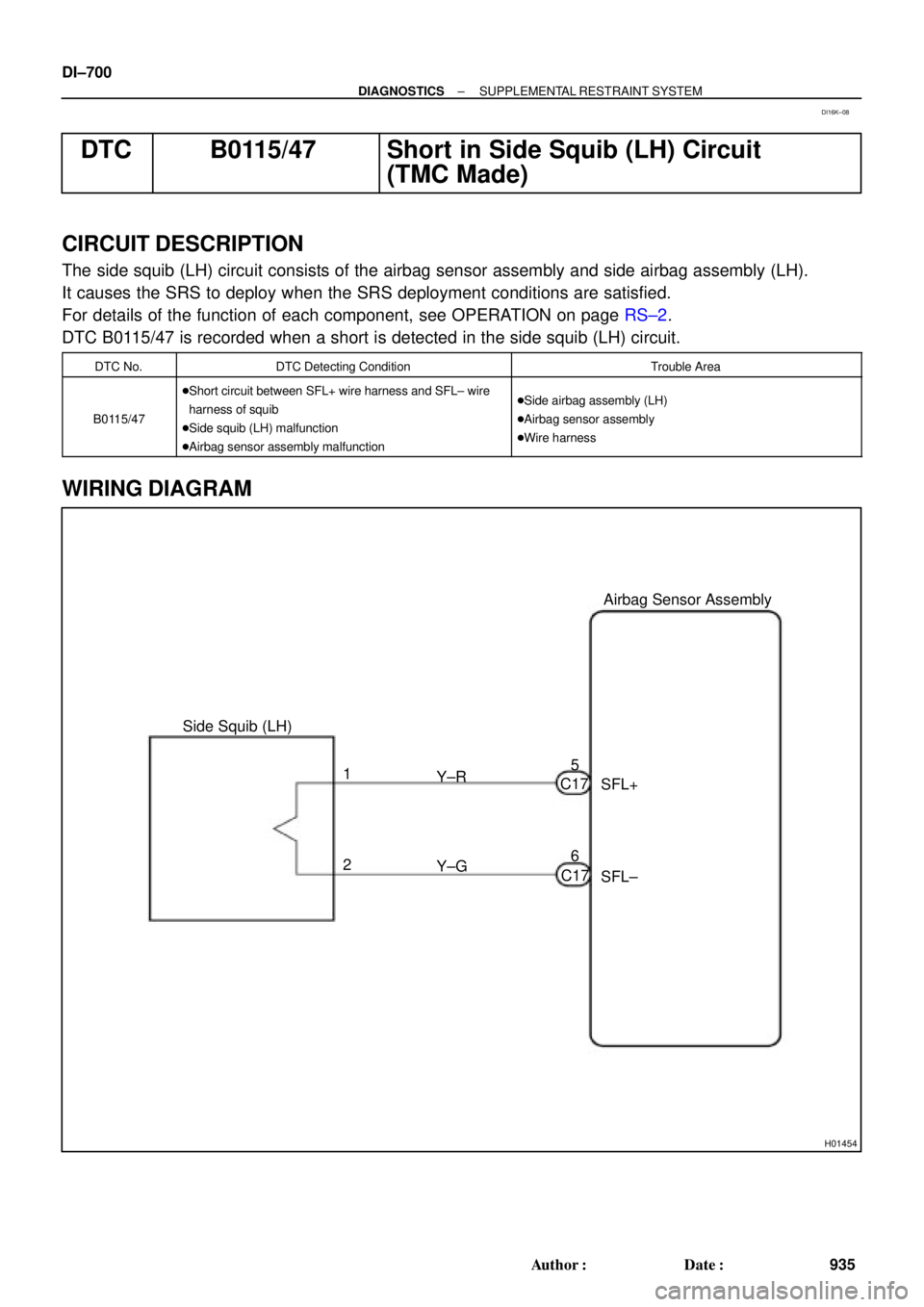
H01454
Side Squib (LH)Airbag Sensor Assembly
SFL+
SFL± Y±R
Y±G 1
26 5
C17
C17 DI±700
± DIAGNOSTICSSUPPLEMENTAL RESTRAINT SYSTEM
935 Author�: Date�:
DTC B0115/47 Short in Side Squib (LH) Circuit
(TMC Made)
CIRCUIT DESCRIPTION
The side squib (LH) circuit consists of the airbag sensor assembly and side airbag assembly (LH).
It causes the SRS to deploy when the SRS deployment conditions are satisfied.
For details of the function of each component, see OPERATION on page RS±2.
DTC B0115/47 is recorded when a short is detected in the side squib (LH) circuit.
DTC No.DTC Detecting ConditionTrouble Area
B0115/47
�Short circuit between SFL+ wire harness and SFL± wire
harness of squib
�Side squib (LH) malfunction
�Airbag sensor assembly malfunction�Side airbag assembly (LH)
�Airbag sensor assembly
�Wire harness
WIRING DIAGRAM
DI16K±08
Page 1913 of 4592
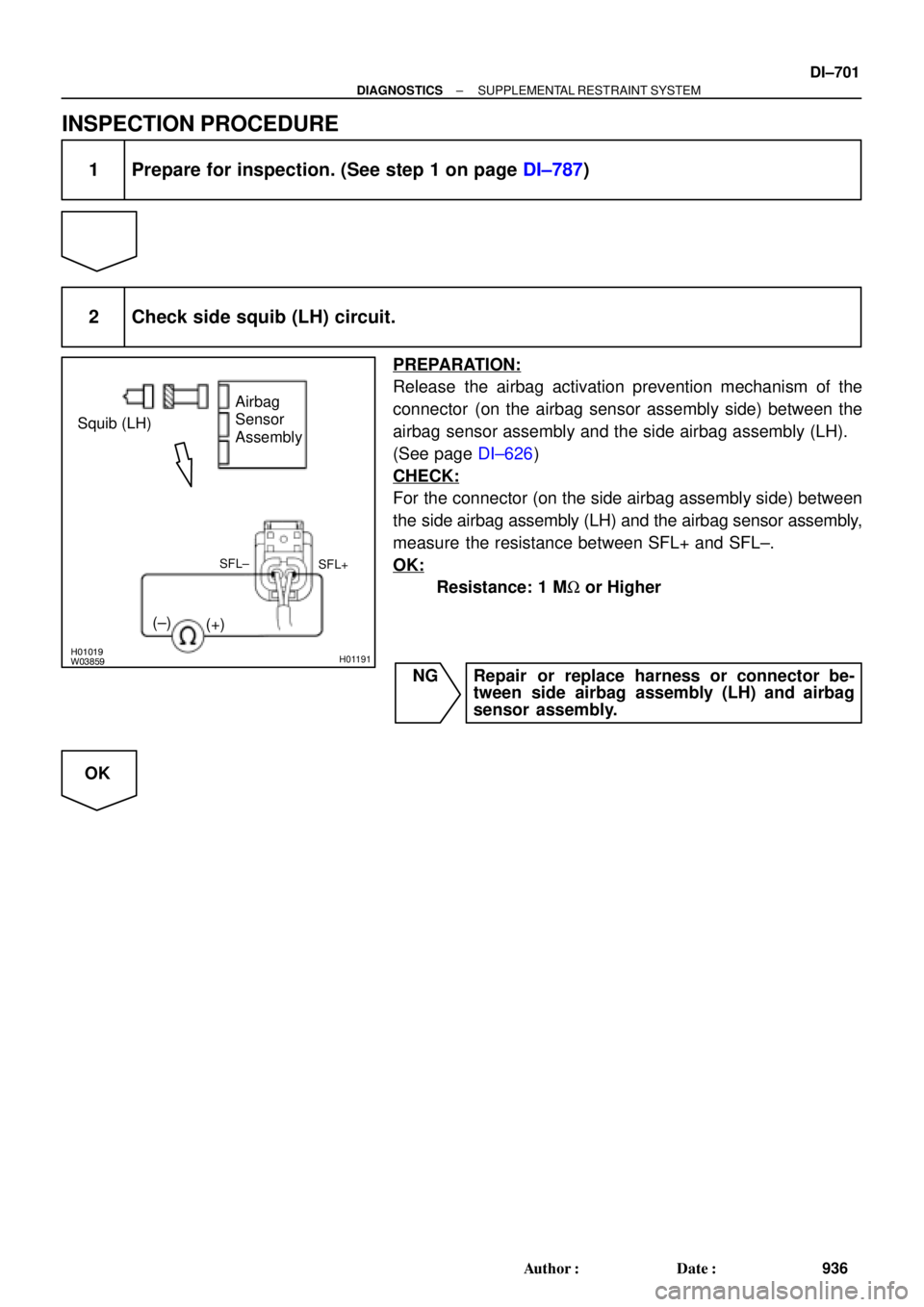
H01019W03859H01191
Squib (LH)Airbag
Sensor
Assembly
SFL+
(±)
(+)
SFL±
± DIAGNOSTICSSUPPLEMENTAL RESTRAINT SYSTEM
DI±701
936 Author�: Date�:
INSPECTION PROCEDURE
1 Prepare for inspection. (See step 1 on page DI±787)
2 Check side squib (LH) circuit.
PREPARATION:
Release the airbag activation prevention mechanism of the
connector (on the airbag sensor assembly side) between the
airbag sensor assembly and the side airbag assembly (LH).
(See page DI±626)
CHECK:
For the connector (on the side airbag assembly side) between
the side airbag assembly (LH) and the airbag sensor assembly,
measure the resistance between SFL+ and SFL±.
OK:
Resistance: 1 MW or Higher
NG Repair or replace harness or connector be-
tween side airbag assembly (LH) and airbag
sensor assembly.
OK
Page 1914 of 4592
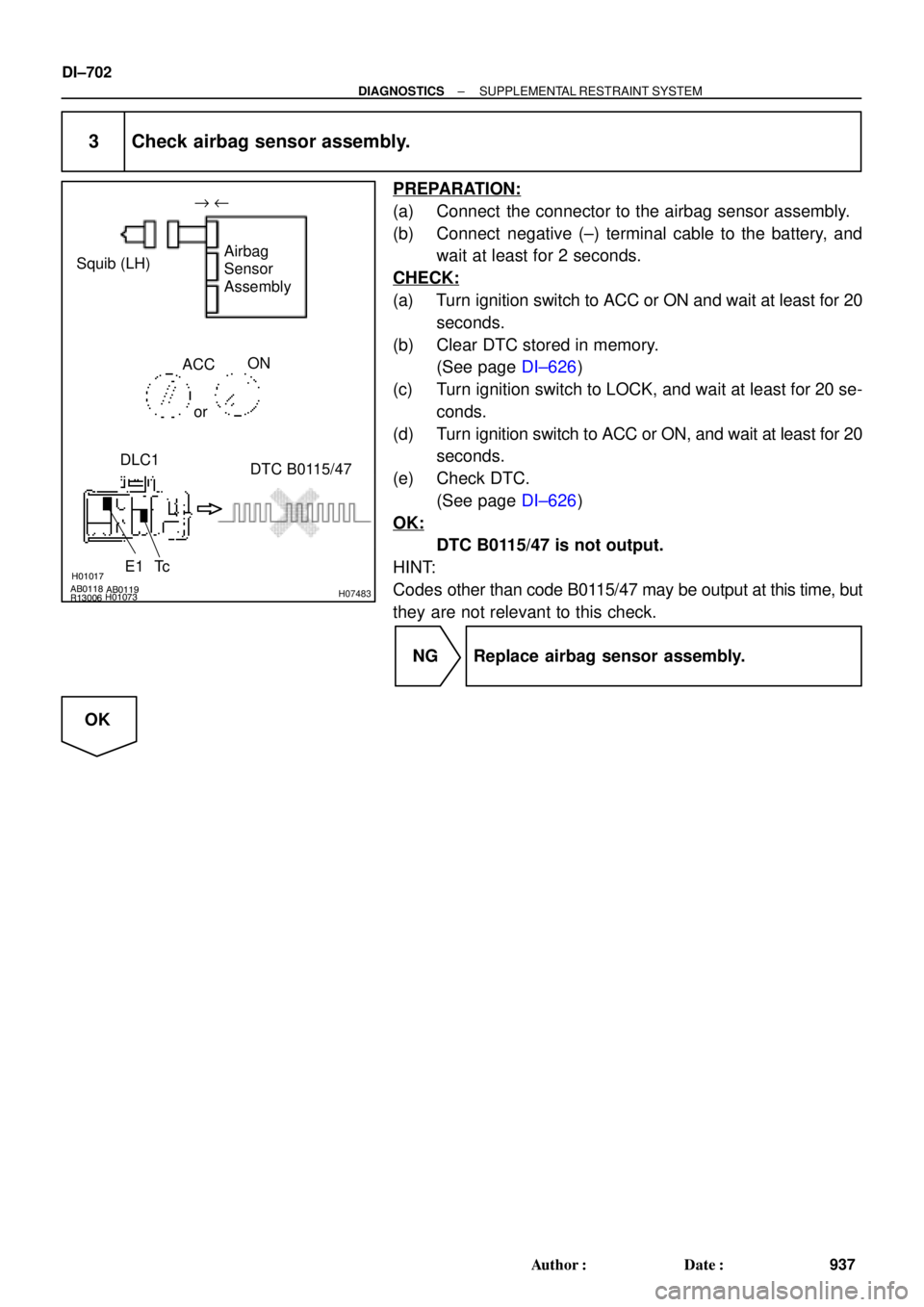
AB0118
R13006AB0119H01017
H01073H07483
Squib (LH)Airbag
Sensor
Assembly
E1 TcACC
or
DTC B0115/47
ON " u
DLC1
DI±702
± DIAGNOSTICSSUPPLEMENTAL RESTRAINT SYSTEM
937 Author�: Date�:
3 Check airbag sensor assembly.
PREPARATION:
(a) Connect the connector to the airbag sensor assembly.
(b) Connect negative (±) terminal cable to the battery, and
wait at least for 2 seconds.
CHECK:
(a) Turn ignition switch to ACC or ON and wait at least for 20
seconds.
(b) Clear DTC stored in memory.
(See page DI±626)
(c) Turn ignition switch to LOCK, and wait at least for 20 se-
conds.
(d) Turn ignition switch to ACC or ON, and wait at least for 20
seconds.
(e) Check DTC.
(See page DI±626)
OK:
DTC B0115/47 is not output.
HINT:
Codes other than code B0115/47 may be output at this time, but
they are not relevant to this check.
NG Replace airbag sensor assembly.
OK
Page 1915 of 4592

DTC B0115/47 DLC1
± DIAGNOSTICSSUPPLEMENTAL RESTRAINT SYSTEM
DI±703
938 Author�: Date�:
4 Check side squib (L")
H01018AB0118AB0119R13006H01073H01190
"u
E1
Tc ACC ON
orAirbag
Sensor
Assembly Squib (LH)
DTC B0115/47 DLC1
± DIAGNOSTICSSUPPLEMENTAL RESTRAINT SYSTEM
DI±703
938 Author�: Date�:
4 Check side squib (LH).
PREPARATION:
(a) Turn ignition switch to LOCK.
(b) Disconnect negative (±) terminal cable from the battery,
and wait at least for 90 seconds.
(c) Connect the side airbag assembly (LH) connector.
(d) Connect negative (±) terminal cable to the battery, and
wait at least for 2 seconds.
CHECK:
(a) Turn ignition switch to LOOK, and wait at least for 20 se-
cond.
(b) Turn ignition switch to ACC or ON, and wait at least for 20
seconds.
(c) Clear DTC stored in memory.
(See page DI±626)
(d) Turn ignition switch to LOCK, and wait at least for 20 se-
conds.
(e) Turn ignition switch to ACC or ON, and wait at least for 20
seconds.
(f) Check DTC.
(See page DI±626)
OK:
DTC B0115/47 is not output.
HINT:
Codes other than code B0115/47 may be output at this time, but
they are not relevant to this check.
NG Replace side airbag assembly (LH).
OK
From the results of the above inspection, the malfunctioning part can now be considered normal.
To make sure of this, use the simulation method to check.