1999 TOYOTA CAMRY ignition
[x] Cancel search: ignitionPage 4301 of 4592
![TOYOTA CAMRY 1999 Service Repair Manual ENGINE CONTROL (1MZ±FE)
I8, I9, I10, I11, I12, I13 INJECTOR
2±1 : Approx. 13.8 W
CIR OPN RELAY [R/B NO.1]
3±5 : Closed with starter running
EFI RELAY [ENGINE ROOM J/B NO.2]
3±5 : Closed with igni TOYOTA CAMRY 1999 Service Repair Manual ENGINE CONTROL (1MZ±FE)
I8, I9, I10, I11, I12, I13 INJECTOR
2±1 : Approx. 13.8 W
CIR OPN RELAY [R/B NO.1]
3±5 : Closed with starter running
EFI RELAY [ENGINE ROOM J/B NO.2]
3±5 : Closed with igni](/manual-img/14/57448/w960_57448-4300.png)
ENGINE CONTROL (1MZ±FE)
I8, I9, I10, I11, I12, I13 INJECTOR
2±1 : Approx. 13.8 W
CIR OPN RELAY [R/B NO.1]
3±5 : Closed with starter running
EFI RELAY [ENGINE ROOM J/B NO.2]
3±5 : Closed with ignition SW at ON or ST position
: PARTS LOCATION
CodeSee PageCodeSee PageCodeSee Page
A12C30H830J2431
A2826 (1MZ±FE)H326 (1MZ±FE) J2631
A2926 (1MZ±FE)H426 (1MZ±FE)J27A31
A34A30I127 (1MZ±FE)J28B31
A35B30I827 (1MZ±FE) J2931
C126 (1MZ±FE)I927 (1MZ±FE)J35A31
C226 (1MZ±FE) I1027 (1MZ±FE)J26B31
C730I1127 (1MZ±FE)J4032
C9B30I1227 (1MZ±FE)K127 (1MZ±FE)
C10C30I1327 (1MZ±FE)K227 (1MZ±FE)
D126 (1MZ±FE) I1630M227 (1MZ±FE)
D530J331P127 (1MZ±FE)
E126 (1MZ±FE) J431P227 (1MZ±FE)
E226 (1MZ±FE) J7A31S631
E526 (1MZ±FE)J8B31T227 (1MZ±FE)
E7A30J9A31T331
E8B30J10B31U131
E9C30J1131V127 (1MZ±FE)
E10D30J1231V227 (1MZ±FE)
E11E30J1531V427 (1MZ±FE)
F4A26 (1MZ±FE)J1831V527 (1MZ±FE)
F6C26 (1MZ±FE)J2031V627 (1MZ±FE)
F1432 J2231V727 (1MZ±FE)
: RELAY BLOCKS
CodeSee PageRelay Blocks (Relay Block Location)
124Engine Room R/B No.1 (Engine Compartment Left)
224Engine Room R/B No.2 (Near the Battery)
Page 4307 of 4592

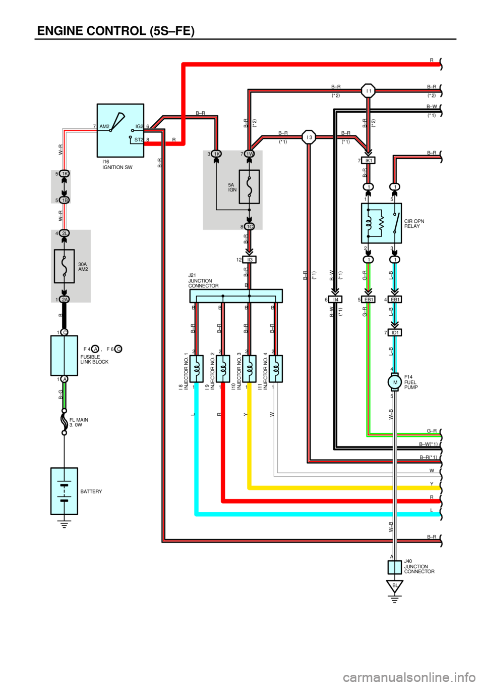
ENGINE CONTROL (5S±FE)
11
11 23 15
CIR OPN
RELAY 5A
IGN
30A
AM2 1K 5
2L 41K 31W7
1C 8 1B 5
2A 1
BL ID1 7EB1 4 EB1 5 II3 12
1 2
1 2
1 2
1 2 C 1
A 176
8 AM2 IG2
ST2
B B B B
5 4 B
G± R
B±W(
*1)
B±R(
*1)
W
Y B±R B±RR
B±R
R
L±B L±B L±B W±B W±BG± RB±R B±R B±RW± R W±R B B±G
B±R B±R B±R B±R
WY RL
IGNITION SW
JUNCTION
CONNE CTOR
FUEL
PUMP
INJE CTOR NO. 1
INJE CTOR NO. 2
INJE CTOR NO. 3
INJE CTOR NO. 4
I16
J21
F1 4
I 8
I 9
I10
I11
BATTERY FL MA IN
3. 0W
JUNCTION
CONNECTOR J40 A
G± R
B±RR
L
B±R
B±W
(
*1)
II4 6
B±W
(
*1)B±W
(
*1)
B±R
(
*1)(
*2)
(
*2)
F 4
FUSIBLE
LINK BLOCKC A, F 6IK1 7I 1
I 3B±R
B±R
B±R B±R B±R
(
*2)
(
*2)
(
*1)
(
*1)
M
Page 4308 of 4592

23 15P
N5
6
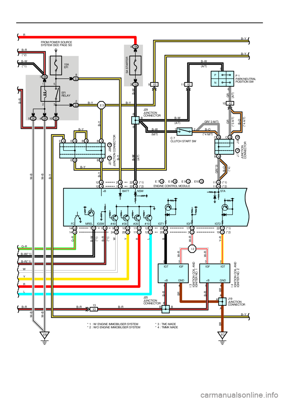
I 2 15A
EFI FROM POWER SOURCE
SYSTEM (
SEE PAGE 50)
EBEC
5A STARTER
1K 4
2K 7
2F 42C10
B EBB
A 14 D7A1C9C10 C17 C 23 C22 A 12A B
A 1A22 A11 1J 3
4 1 4 1
A2 3 3 2 B
B±Y Y W B±R(
*1) B±W(
*1) G±RB± RR
B±Y
B±W
B±O B±W
B± Y
B±Y
Y± R W±R W±RBB± Y B±Y
B±WB± Y
B±YB±R
W±B W±B
B±W
B±W
GR
B±O B±O GR(
*3)
GR BR B±RBRG±R
B±W
B± R
W
Y
W±R
B
FC #40 #30 #20 #10 IGT1 IGF IGT2+B BATT NSW STA(
*4 M/T)
(
*4 A/T) (
*4)
(
A/ T)
(
A/ T)
(
M/T)PARK/NEUTRA
LPOSITION SW
JUNCTION
CO NNE CTOR EFI
RE LA Y
J29P 1
* 1 : W/ ENGINE IMMOBILISER SYSTEM
* 2 : W/O ENGINE IMMOBILISER SYSTEM* 3 : TMC MADE
* 4 : TMMK MADEJUNCTION
CONNECTOR
IGNITION COIL AND
IGNITER NO. 1
IGNITION COIL AND
IGNITER NO. 2
J19
I 3
I 4
A A
BRB±R
2 1
CLUTCH START SW C 7II2 10 II2 11
E 3B±Y
BB
B JUNCTION
CO NNE CTOR J25
B± RIGTIGF IGFIGT
+B GND GND+B
II3 13
B±R B± RC 12 C 11 MREL IGSW
R
LA 14 C24 C25 C11 C12 C3 C 20 C19(
*1)
(
*2)
R (
*1)
L (
*1)
B±Y
II3 9
(
A/ T) (
*3 A/T)
A EAEABB B±W(
*2)
(
*1)
2J8
2J2
A 11 B± Y
A 12 A2A22(
*1)
(
*2)(
*1)
(
*2)
J27
JUNCTION CONNECTORB A, J28
E 7
ENGINE CONTROL MODULEB A, E 8 C, E 9 D, E10 2C 5W±B W±B
A BB CBC GR(
*3 M/T)J 7
JUNCTION
CONNECTORB A, J 8 B±W B±W
B±W
(
A/T)
Page 4313 of 4592

ENGINE CONTROL (5S±FE)
This system utilizes an engine control module and maintains overall control of the engine, transmission and so on. An outline
of the engine control is explained here.
1. INPUT SIGNALS
(1) Engine coolant temp. signal circuit
The engine coolant temp. sensor detects the engine coolant temp. and has a built±in thermistor with a resistance which
varies according to the engine coolant temp. thus the engine coolant temp. is input in the form of a control signal into
TERMINAL THW of the engine control module.
(2) Intake air temp. signal circuit
The intake air temp. sensor detects the intake air temp., which is input as a control signal into TERMINAL THA of the
engine control module.
(3) Oxygen sensor signal circuit
The oxygen density in the exhaust gases is detected and input as a control signal into TERMINAL OX1 (except
California) and OX2 of the engine control module.
(4) RPM signal circuit
Camshaft position and crankshaft position are detected by the camshaft position sensor and crankshaft position sensor.
Camshaft position is input as a control signal to TERMINAL G+ of the engine control module, and engine RPM is input
into TERMINAL NE+.
(5) Throttle signal circuit
The throttle position sensor detects the throttle valve opening angle, which is input as a control signal into TERMINAL
VTA of the engine control module.
(6) Vehicle speed signal circuit
The vehicle speed sensor, installed inside the transmission, detects the vehicle speed and inputs a control signal into
TERMINAL SPD of the engine control module.
(7) Park/Neutral position SW signal circuit (A/T)
The Park/Neutral position SW detects whether the shift position are in neutral, parking or not, and inputs a control signal
into TERMINAL STA of the engine control module.
(8) A/C SW signal circuit
The A/C amplifier function is built in the engine control module. The A/C SW signal inputs into the TERMINAL A/C SW of
the engine control module.
(9) Battery signal circuit
Voltage is constantly applied to TERMINAL BATT of the engine control module. When the ignition SW is turned on, the
voltage for engine control module start±up power supply is applied to TERMINAL +B of engine control module via EFI
relay.
(10) Intake air volume signal circuit
Intake air volume is detected by the manifold absolute pressure sensor (for manifold pressure) and is input as a control
signal into TERMINAL PIN of the engine control module.
(11) Starter signal circuit
To confirm whether the engine is cranking, the voltage applied to the starter motor during cranking is detected and the
signal is input into TERMINAL NSW of the engine control module as a control signal.
(12) Engine knock signal circuit
Engine knocking is detected by knock sensor 1 and the signal is input into TERMINAL KNK as a control signal.
(13) Electrical load signal circuit
The signal when systems such as the rear window defogger, headlights, etc. Which cause a high electrical burden are
on is input to TERMINAL ELS as a control signal.
(14) Air fuel ratio signal circuit (California)
The air fuel ratio is detected and input as a control signal into TERMINAL AF+ of the engine control module.
SYSTEM OUTLINE
Page 4314 of 4592

2. CONTROL SYSTEM
*SFI system
The SFI system monitors the engine condition through the signals, which are input from each sensor (Input signals from
(1) to (14) etc.) to the engine control module. The best fuel injection volume is decided based on this data and the
program memorized by the engine control module, and the control signal is output to TERMINALS #10, #20, #30 and
#40 of the engine control module to operate the injector. (Inject the fuel). The SFI system produces control of fuel
injection operation by the engine control module in response to the driving conditions.
*ESA system
The ESA system monitors the engine condition through the signals, which are input to the engine control module from
each sensor (Input signals from (1), (2), (4) to (12) etc.) the best ignition timing is detected according to this data and the
memorized data in the engine control module, and the control signal is output to TERMINALS IGT1 and IGT2. This
signal controls the igniter to provide the best ignition timing for the driving conditions.
*Idle Air Control system
The IAC system (Step motor type) increases the RPM and provides idling stability for fast idle±up when the engine is
cold and when the idle speed has dropped due to electrical load, etc. The engine control module evaluates the signals
from each sensor (Input signals (1), (4) to (8), (13) etc.), outputs current to TERMINALS ISCO and ISCC, and controls
the idle air control valve.
*Fuel pump control system
The engine control module operation outputs to TERMINAL FC and controls the CIR OPN relay. Thus controls the fuel
pump drive speed in response to conditions.
*EGR control system
The EGR cut control system controls the VSV (EGR) by evaluating the signals from each sensor which are input to the
engine control module (Input signals (1), (5), (6), (9) etc.) and by sending output to TERMINAL EGR of the engine
control module.
*A/C conditioning operation system
In addition to the conventional A/C cut control, the engine control module performs the air conditioning operation as well
since the A/C amplifier function is built in it.
3. DIAGNOSIS SYSTEM
With the diagnosis system, when there is a malfunctioning in the engine control module signal system, the malfunction
system is recorded in the memory. The malfunctioning system can then be found by reading the display (Code) of the
malfunction indicator lamp.
4. FAIL±SAFE SYSTEM
When a malfunction occurs in any system, if there is a possibility of engine trouble being caused by continued control based
on the signals from that system, the fail±safe system either controls the system by using data (Standard values) recorded in
the engine control module memory or else stops the engine.
E7 (A), E8 (B), E9 (C), E10 (D) ENGINE CONTROL MODULE
Voltage at engine control module wiring connector
BATT±E1 : Always 9.0±14.0 volts
+B±E1 :9.0±14.0 volts (Ignition SW at ON position)
VC±E2 :4.5± 5.5 volts (Ignition SW at ON position)
VTA±E2 :0.3± 0.8 volts (Ignition SW on and throttle valve fully closed)
3.2±4.9 volts (Ignition SW on and throttle valve open)
PIM±E2 :3.3± 3.9 volts (Ignition SW at ON position)
THA±E2 :0.5±3.4 volts (Ignition SW on and intake air temp. 20°C, 68°F)
THW±E2 :0.2± 1.0 volts (Ignition SW on and coolant temp. 80°C, 176°F)
STA±E1 :6.0±14.0 volts (Engine cranking)
W±E1 :9.0±14.0 volts (No trouble and engine running)
TE1±E1 :9.0±14.0 volts (Ignition SW at ON position)
NSW±E1 :0± 3.0 volts (Ignition SW on and Park/Neutral position SW position P or N position)
9.0±14.0 volts (Ignition SW on and except Park/Neutral position SW position P or N position)
IGT1, IGT2±E1 : Pulse generation (Engine cranking or idling)
#10, #20, #30, #40±E01, E02 :9.0±14.0 volts (Ignition SW at ON position)
RESISTANCE AT ENGINE CONTROL MODULE WIRING CONNECTORS
(Disconnect wiring connector)
VC±E2 :2.5±5.0 kW
THA±E2 :2.21±2.69 kW (Intake air temp. 20°C, 68°F)
THW±E2 :0.29±0.354 kW (Coolant temp. 80°C, 176°F)
SERVICE HINTS
Page 4329 of 4592

HEADLIGHT (w/ DAYTIME RUNNING LIGHT)
The current from the FL MAIN is always flowing from the MAIN fuse to HEAD relay (Coil side) to TERMINAL H±LP of the
daytime running light relay (Main), from DOME fuse to TERMINAL +B of the daytime running light relay (Main) and from the
ALT fuse to Taillight relay (Coil side) to TERMINAL TAIL (TMMK Made) of the daytime running light relay (Main).
When the ignition SW is turned on, the current flowing through the GAUGE fuse flows to TERMINAL IG of the daytime
running light relay (Main).
1. DAYTIME RUNNING LIGHT OPERATION
When the engine is started, voltage generated at TERMINAL L of the generator is applied to TERMINAL CHG± of the
daytime running light relay (Main). If the parking brake lever is pulled up (Parking brake SW on) at this time, the relay is not
activated so the daytime running light system does not operate. If the parking brake lever is then released (Parking brake
SW off), a signal is input to TERMINAL PKB of the relay.
This activates the daytime running light relay (Main) and the HEAD relay is turned to on, so the current flows from the MAIN
fuse to the HEAD relay (Point side) to TERMINAL 1 of the DIM relay to TERMINAL 4 to H±LP LH (LWR), H±LP RH (LWR)
fuses to TERMINAL 1 of the headlights to TERMINAL 3 to TERMINAL 1 of the daytime running light resistor to TERMINAL 2
to GROUND, causing the headlights to light up (Headlights light up dimmer than normal brightness.). Once the daytime
running light system operates and the headlights light up, the headlights remain on even if the parking brake lever is pulled
up (Parking brake SW on).
If the engine stalls and the ignition SW remains on, the headlights remain light up even through current is no longer output
from TERMINAL L of the generator. If the ignition SW is then turned off, the headlights go off.
If the engine is started with the parking brake lever released (Parking brake SW off), the daytime running light system
operates and headlights light up when the engine starts.
2. HEADLIGHT OPERATION
When the light control SW is switched to HEAD position and the dimmer SW is set to LOW position, causing the daytime
running light relay (Main) and the HEAD relay to turn on, so the current flows from the MAIN fuse to HEAD relay (Point side)
to DRL NO.2 fuse to TERMINAL 3 of the DRL NO.4 relay to TERMINAL 4 to TERMINAL H±ON of the daytime running light
relay (Main) to TERMINAL H to TERMINAL 3 of the integration relay to TERMINAL 4 to TERMINAL 13 of the light control
SW to TERMINAL 16 to GROUND, activating the DRL. NO.4 relay. The current to HEAD relay (Point side) then flows to
TERMINAL 1 of the DIM relay to TERMINAL 4 to H±LP LH (LWR), H±LP RH (LWR) fuses to TERMINAL 1 of the headlights
to TERMINAL 3 to TERMINAL 1 of the DRL NO.4 relay to TERMINAL 2 to GROUND, causing the headlights to light up at
normal intensity.
When the light control SW is switched to HEAD position and the dimmer SW is set to HIGH position, the signal from the
dimmer SW is input to the daytime running light relay (Main). This activates the daytime running light relay (Main) and the
HEAD relay is turned on, so the current flows from the MAIN fuse to HEAD relay (Point side) to TERMINAL 1 of the DIM
relay to TERMINAL 3 to TERMINAL DIM of the daytime running light relay (Main), activating the DIM relay. This causes
current to flow from TERMINAL 1 of the DIM relay to TERMINAL 2 to HEAD LH (UPR), HEAD RH (UPR) fuses to TERMINAL
2 of the headlights to TERMINAL 3 to TERMINAL 1 of the DRL NO.4 relay to TERMINAL 2 to GROUND, causing the
headlights to light up at high beam and the high beam indicator light to light up.
When the dimmer SW is switched to FLASH position, the signal from the dimmer SW is input to the daytime running light
relay (Main). This activates the daytime running light relay (Main) and the HEAD relay is turned on, so the current flows from
the MAIN fuse to HEAD relay (Point side) to DRL NO.2 fuse to TERMINAL 3 of the DRL NO.4 relay to TERMINAL 4 to
TERMINAL H±ON of the daytime running light relay (Main) to TERMINAL H to TERMINAL 8 of the dimmer SW to
TERMINAL 16 to GROUND, activating the DRL NO.4 relay. At the same time, the current flows from the TERMINAL 1 of the
DIM relay to TERMINAL 3 to TERMINAL DIM of the daytime running light relay (Main), activating the DIM relay, and also
flows from the HEAD LH (UPR), HEAD RH (UPR) fuses to TERMINAL 2 of the headlights to TERMINAL 3 to TERMINAL 1 of
the DRL NO.4 relay to TERMINAL 2 to GROUND, causing the headlights to light up at high beam and the high beam
indicator light to light up.
SYSTEM OUTLINE
Page 4330 of 4592

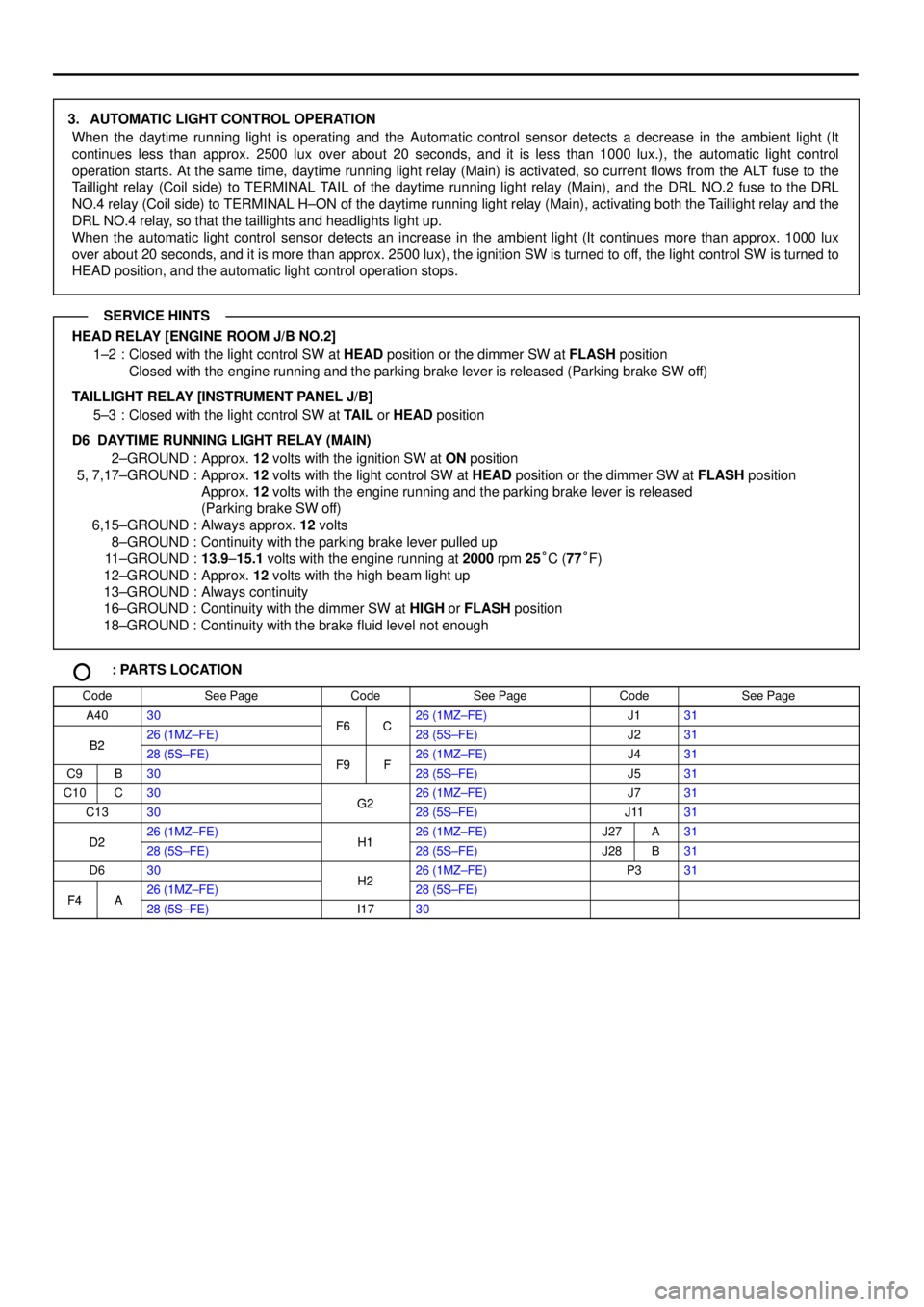
3. AUTOMATIC LIGHT CONTROL OPERATION
When the daytime running light is operating and the Automatic control sensor detects a decrease in the ambient light (It
continues less than approx. 2500 lux over about 20 seconds, and it is less than 1000 lux.), the automatic light control
operation starts. At the same time, daytime running light relay (Main) is activated, so current flows from the ALT fuse to the
Taillight relay (Coil side) to TERMINAL TAIL of the daytime running light relay (Main), and the DRL NO.2 fuse to the DRL
NO.4 relay (Coil side) to TERMINAL H±ON of the daytime running light relay (Main), activating both the Taillight relay and the
DRL NO.4 relay, so that the taillights and headlights light up.
When the automatic light control sensor detects an increase in the ambient light (It continues more than approx. 1000 lux
over about 20 seconds, and it is more than approx. 2500 lux), the ignition SW is turned to off, the light control SW is turned to
HEAD position, and the automatic light control operation stops.
HEAD RELAY [ENGINE ROOM J/B NO.2]
1±2 : Closed with the light control SW at HEAD position or the dimmer SW at FLASH position
Closed with the engine running and the parking brake lever is released (Parking brake SW off)
TAILLIGHT RELAY [INSTRUMENT PANEL J/B]
5±3 : Closed with the light control SW at TAIL or HEAD position
D6 DAYTIME RUNNING LIGHT RELAY (MAIN)
2±GROUND : Approx. 12 volts with the ignition SW at ON position
5, 7,17±GROUND : Approx. 12 volts with the light control SW at HEAD position or the dimmer SW at FLASH position
Approx. 12 volts with the engine running and the parking brake lever is released
(Parking brake SW off)
6,15±GROUND : Always approx. 12 volts
8±GROUND : Continuity with the parking brake lever pulled up
11±GROUND :13.9±15.1 volts with the engine running at 2000 rpm 25°C (77°F)
12±GROUND : Approx. 12 volts with the high beam light up
13±GROUND : Always continuity
16±GROUND : Continuity with the dimmer SW at HIGH or FLASH position
18±GROUND : Continuity with the brake fluid level not enough
: PARTS LOCATION
CodeSee PageCodeSee PageCodeSee Page
A4030F6C26 (1MZ±FE)J131
B226 (1MZ±FE)F6C28 (5S±FE)J231B228 (5S±FE)F9F26 (1MZ±FE)J431
C9B30F9F28 (5S±FE)J531
C10C30G226 (1MZ±FE)J731
C1330G228 (5S±FE)J1131
D226 (1MZ±FE)H126 (1MZ±FE)J27A31D228 (5S±FE)H128 (5S±FE)J28B31
D630H226 (1MZ±FE)P331
F4A26 (1MZ±FE)H228 (5S±FE)F4A28 (5S±FE)I1730
SERVICE HINTS
Page 4336 of 4592

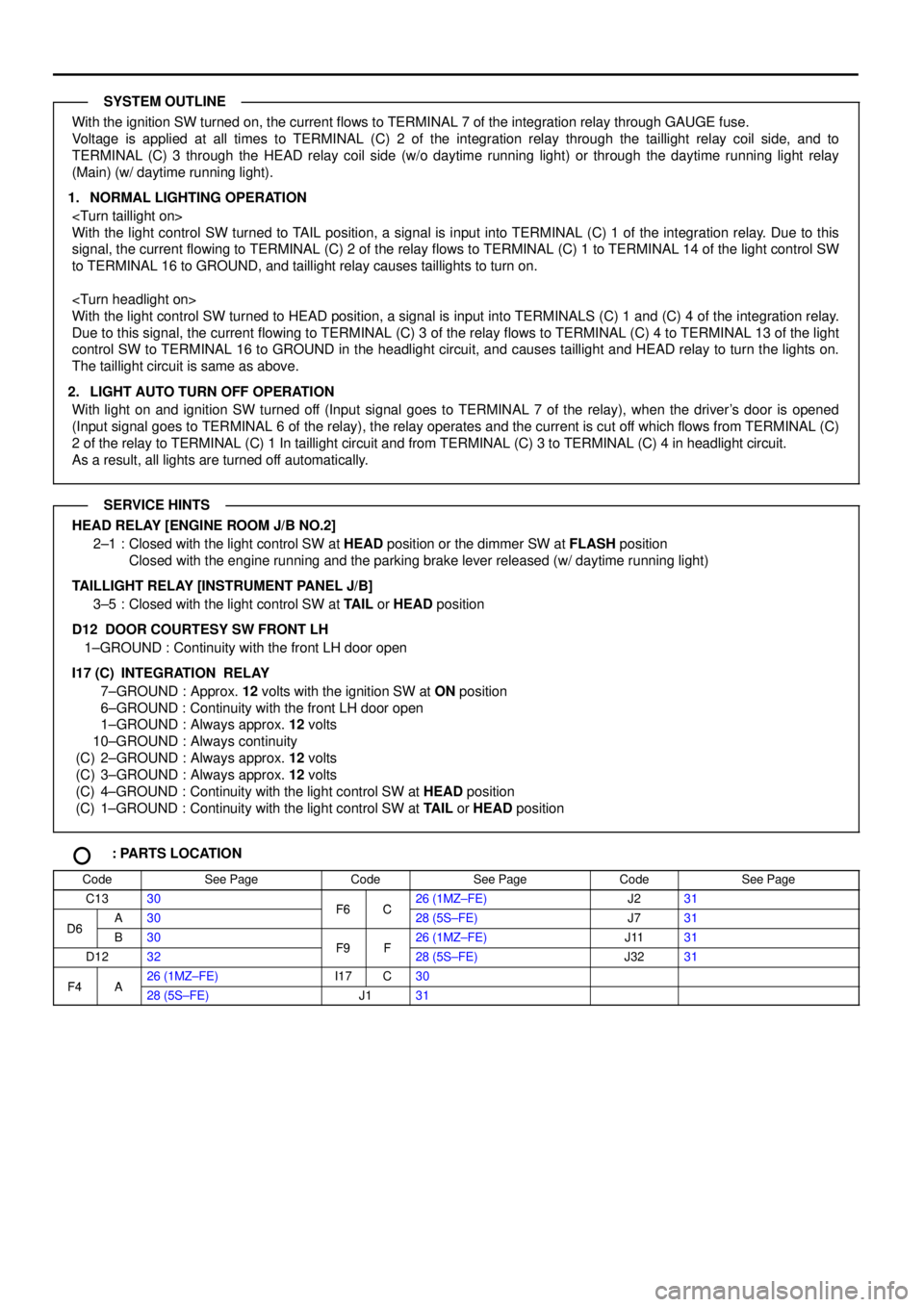
With the ignition SW turned on, the current flows to TERMINAL 7 of the integration relay through GAUGE fuse.
Voltage is applied at all times to TERMINAL (C) 2 of the integration relay through the taillight relay coil side, and to
TERMINAL (C) 3 through the HEAD relay coil side (w/o daytime running light) or through the daytime running light relay
(Main) (w/ daytime running light).
1. NORMAL LIGHTING OPERATION
With the light control SW turned to TAIL position, a signal is input into TERMINAL (C) 1 of the integration relay. Due to this
signal, the current flowing to TERMINAL (C) 2 of the relay flows to TERMINAL (C) 1 to TERMINAL 14 of the light control SW
to TERMINAL 16 to GROUND, and taillight relay causes taillights to turn on.
With the light control SW turned to HEAD position, a signal is input into TERMINALS (C) 1 and (C) 4 of the integration relay.
Due to this signal, the current flowing to TERMINAL (C) 3 of the relay flows to TERMINAL (C) 4 to TERMINAL 13 of the light
control SW to TERMINAL 16 to GROUND in the headlight circuit, and causes taillight and HEAD relay to turn the lights on.
The taillight circuit is same as above.
2. LIGHT AUTO TURN OFF OPERATION
With light on and ignition SW turned off (Input signal goes to TERMINAL 7 of the relay), when the driver's door is opened
(Input signal goes to TERMINAL 6 of the relay), the relay operates and the current is cut off which flows from TERMINAL (C)
2 of the relay to TERMINAL (C) 1 In taillight circuit and from TERMINAL (C) 3 to TERMINAL (C) 4 in headlight circuit.
As a result, all lights are turned off automatically.
HEAD RELAY [ENGINE ROOM J/B NO.2]
2±1 : Closed with the light control SW at HEAD position or the dimmer SW at FLASH position
Closed with the engine running and the parking brake lever released (w/ daytime running light)
TAILLIGHT RELAY [INSTRUMENT PANEL J/B]
3±5 : Closed with the light control SW at TAIL or HEAD position
D12 DOOR COURTESY SW FRONT LH
1±GROUND : Continuity with the front LH door open
I17 (C)
INTEGRATION RELAY
7±GROUND : Approx. 12 volts with the ignition SW at ON position
6±GROUND : Continuity with the front LH door open
1±GROUND : Always approx. 12 volts
10±GROUND : Always continuity
(C) 2±GROUND : Always approx. 12 volts
(C) 3±GROUND : Always approx. 12 volts
(C) 4±GROUND : Continuity with the light control SW at HEAD position
(C) 1±GROUND : Continuity with the light control SW at TAIL or HEAD position
: PARTS LOCATION
CodeSee PageCodeSee PageCodeSee Page
C1330F6C26 (1MZ±FE)J231
D6A30F6C28 (5S±FE)J731D6B30F9F26 (1MZ±FE)J1131
D1232F9F28 (5S±FE)J3231
F4A26 (1MZ±FE)I17C30F4A28 (5S±FE)J131
SYSTEM OUTLINE
SERVICE HINTS