1999 TOYOTA CAMRY ignition
[x] Cancel search: ignitionPage 4378 of 4592
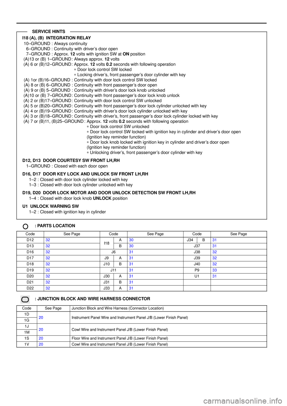
I18 (A), (B) INTEGRATION RELAY
10±GROUND : Always continuity
6±GROUND : Continuity with driver's door open
7±GROUND : Approx. 12 volts with ignition SW at ON position
(A)13 or (B) 1±GROUND : Always approx. 12 volts
(A) 6 or (B)12±GROUND : Approx. 12 volts 0.2 seconds with following operation
* Door lock control SW locked
* Locking driver's, front passenger's door cylinder with key
(A) 1or (B)16±GROUND : Continuity with door lock control SW locked
(A) 8 or (B) 6±GROUND : Continuity with front passenger's door open
(A) 9 or (B) 5±GROUND : Continuity with driver's door lock knob unlocked
(A)10 or (B) 7±GROUND : Continuity with front passenger's door lock knob unlock
(A) 2 or (B)17±GROUND : Continuity with door lock control SW unlocked
(A) 5 or (B)20±GROUND : Continuity with front passenger's door lock cylinder unlocked with key
(A) 4 or (B)19±GROUND : Continuity with driver's door lock cylinder unlocked with key
(A) 3 or (B)18±GROUND : Continuity with driver's, front passenger's door lock cylinder locked with key
(A) 7 or (B)11, (B)25±GROUND : Approx. 12 volts 0.2 seconds with following operation
* Door lock control SW unlocked
* Door lock control SW locked with ignition key in cylinder and driver's door open
(Ignition key reminder function)
* Door lock knob locked with ignition key in cylinder and driver's door open
(Ignition key reminder function)
* Unlocking driver's, front passenger's door cylinder with key
D12, D13 DOOR COURTESY SW FRONT LH,RH
1±GROUND : Closed with each door open
D16, D17 DOOR KEY LOCK AND UNLOCK SW FRONT LH,RH
1±2 : Closed with door lock cylinder locked with key
1±3 : Closed with door lock cylinder unlocked with key
D19, D20 DOOR LOCK MOTOR AND DOOR UNLOCK DETECTION SW FRONT LH,RH
1±4 : Closed with door lock knob UNLOCK position
U1 UNLOCK WARNING SW
1±2 : Closed with ignition key in cylinder
: PARTS LOCATION
CodeSee PageCodeSee PageCodeSee Page
D1232I18A30J34B31
D1332I18B30J3731
D1632J631J3832
D1732J9A31J3932
D1832J10B31J4032
D1932J1131P933
D2032J30A31U131
D2132J31B31
D2232J33A31
: JUNCTION BLOCK AND WIRE HARNESS CONNECTOR
CodeSee PageJunction Block and Wire Harness (Connector Location)
1D20Instrument Panel Wire and Instrument Panel J/B (Lower Finish Panel)1G20Instrument Panel Wire and Instrument Panel J/B (Lower Finish Panel)
1J20Cowl Wire and Instrument Panel J/B (Lower Finish Panel)1M20Cowl Wire and Instrument Panel J/B (Lower Finish Panel)
1S20Floor Wire and Instrument Panel J/B (Lower Finish Panel)
1V20Cowl Wire and Instrument Panel J/B (Lower Finish Panel)
SERVICE HINTS
Page 4383 of 4592

DOOR LOCK CONTROL (TMMK MADE)
Current always flows to TERMINAL (A) 13 (w/o theft deterrent system), (B) 1 (w/ theft deterrent system) of the integration
relay through the DOOR fuse.
When the ignition SW is turned on, the current flowing through the GAUGE Fuse flows to TERMINAL 7 of the integration
relay to TERMINAL (A) 12 (w/o theft deterrent system), (B) 3 (w/ theft deterrent system) to the power relay (Coil side) to
GROUND
.
1. MANUAL LOCK OPERATION
When the door lock control SW or door key lock and unlock SW are operated to LOCK position, a lock signal is input to
TERMINAL (A) 1 or (A) 3 (w/o theft deterrent system), (B) 16 or (B) 18 (w/ theft deterrent system) of the integration relay and
causes the relay to function. Current flows from TERMINAL (A) 13 (w/o theft deterrent system), (B) 1 (w/ theft deterrent
system) of the relay to (A) 6 (w/o theft deterrent system), (B) 12 (w/ theft deterrent system) to TERMINAL 2 of the door lock
motors to TERMINAL 3 to TERMINAL (A) 7 (w/o theft deterrent system), (B) 11
and (B) 25 (w/ theft deterrent system) of the
relay to TERMINAL 10 to GROUND and the door lock motor causes the door to lock.
2. MANUAL UNLOCK OPERATION
When the door lock control SW or door key lock and unlock SW are operated to UNLOCK position, an unlock signal is input
to TERMINAL (A) 2, (A) 4 or (A) 5 (w/o theft deterrent system), (B) 17, (B) 19 or (B) 20 (w/ theft deterrent system) of the
integration relay and causes the relay to function. Current flows from TERMINAL (A) 13 (w/o theft deterrent system),
(B) 1
(w/ theft deterrent system) of the relay to TERMINAL (A) 7 (w/o theft deterrent system), (B) 11 and (B) 25 (w/ theft deterrent
system) to TERMINAL 3 of the door lock motors to TERMINAL 2 to TERMINAL (A) 6 (w/o theft Deterrent system), (B) 12 (w/
theft deterrent system) of the relay to TERMINAL 10 to GROUND and door lock motors causes door to unlock.
3. DOUBLE OPERATION UNLOCK OPERATION
When the door key lock and unlock SW front LH is turned to the unlock side, only the driver's door is mechanically unlocked.
Turning the door key lock and unlock SW front LH to the unlock side causes a signal to be input to TERMINAL (A) 4 (w/o
theft deterrent system), (B) 19 (w/ theft deterrent system) of the relay, and if the signal is input again within 3 seconds by
turning the SW to the unlock side again, current flows from TERMINAL (A) 7 (w/o theft deterrent system),
(B) 11 and (B) 25
(w/ theft deterrent system) of the integration relay to TERMINAL 3 of the door lock motors to TERMINAL 2 of the door lock
motors to TERMINAL (A) 6 (w/o theft deterrent system), (B) 12 (w/ theft deterrent system) of the relay to TERMINAL 10 to
GROUND, causing the door lock motors to operate and unlock the doors.
4. IGNITION KEY REMINDER OPERATION
*Operating door lock knob (Operation of door lock motors)
With ignition key in cylinder (Unlock warning SW on), when the door is opened and locked using door lock knob (Door
lock motor), the door is locked once but each door is unlocked soon by the function of the relay. As a result, the current
flows from TERMINAL (A) 13 (w/o theft deterrent system), (B) 1 (w/ theft deterrent system) of the integration relay to
TERMINAL (A) 7 (w/o theft deterrent system),(B) 11 and (B) 25
(w/ theft deterrent system) to TERMINAL 3 of the door
lock motors to TERMINAL 2 of the door lock motors to TERMINAL (A) 6 (w/o theft deterrent system), (B) 12 (w/ theft
deterrent system) of the relay to TERMINAL 10 to GROUND and causes all the doors to unlock.
*Operating door lock control SW or door key lock and unlock SW
With ignition key in cylinder (Unlock warning SW on), when the door is opened and locked using door lock control SW or
key SW, the door is locked once but each door is unlock by the function of SW contained in motors, which the signal is
input to TERMINAL (A) 9 or (A) 10 (w/o theft deterrent system), (B) 5 or (B) 7 (w/ theft deterrent system) of the relay.
According to this input signal, the current in ECU flows from TERMINAL (A) 13 (w/o theft deterrent system), (B) 1 (w/
theft deterrent system) of the relay to TERMINAL (A) 7 (w/o theft deterrent system), (B) 11 and (B) 25 (w/ theft deterrent
system) to TERMINAL 3 of the door lock motors to TERMINAL 2 of the door lock motors to TERMINAL (A) 6 (w/o theft
deterrent system), (B) 12 (w/ theft deterrent system) of the relay to TERMINAL 10 to GROUND and causes all the doors
to unlock.
*In case of key less lock
With ignition key in cylinder (Unlock warning SW on), when the unlock function is disturbed more than 0.2 seconds, for
example pushing the door lock knob etc., the door holds on lock condition. Closing the door after, door courtesy SW
inputs the signal into TERMINAL 6 or (A) 8 (w/o theft deterrent system), (B) 6 (w/ theft deterrent system) of the
integration relay. By this input signal, the ECU works and current flows from
TERMINAL (A) 13 (w/o theft deterrent
system), (B) 1 (w/ theft deterrent system) of the relay to TERMINAL (A) 7 (w/o theft deterrent system), (B) 11 and (B) 25
(w/ theft deterrent system) to TERMINAL 3 of the door lock motors to TERMINAL 2 of the door lock motors to
TERMINAL (A) 6 (w/o theft deterrent system), (B) 12 (w/ theft deterrent system) of the relay to TERMINAL 10 to
GROUND and causes all the doors to unlock.
SYSTEM OUTLINE
Page 4384 of 4592
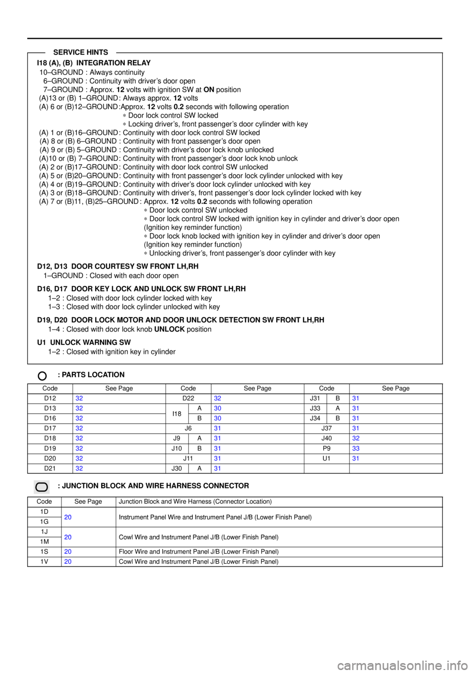
I18 (A), (B) INTEGRATION RELAY
10±GROUND : Always continuity
6±GROUND : Continuity with driver's door open
7±GROUND : Approx. 12 volts with ignition SW at ON position
(A)13 or (B) 1±GROUND : Always approx. 12 volts
(A) 6 or (B)12±GROUND :Approx. 12 volts 0.2 seconds with following operation
* Door lock control SW locked
* Locking driver's, front passenger's door cylinder with key
(A) 1 or (B)16±GROUND : Continuity with door lock control SW locked
(A) 8 or (B) 6±GROUND : Continuity with front passenger's door open
(A) 9 or (B) 5±GROUND : Continuity with driver's door lock knob unlocked
(A)10 or (B) 7±GROUND : Continuity with front passenger's door lock knob unlock
(A) 2 or (B)17±GROUND : Continuity with door lock control SW unlocked
(A) 5 or (B)20±GROUND : Continuity with front passenger's door lock cylinder unlocked with key
(A) 4 or (B)19±GROUND : Continuity with driver's door lock cylinder unlocked with key
(A) 3 or (B)18±GROUND : Continuity with driver's, front passenger's door lock cylinder locked with key
(A) 7 or (B)11, (B)25±GROUND : Approx. 12 volts 0.2 seconds with following operation
* Door lock control SW unlocked
* Door lock control SW locked with ignition key in cylinder and driver's door open
(Ignition key reminder function)
* Door lock knob locked with ignition key in cylinder and driver's door open
(Ignition key reminder function)
* Unlocking driver's, front passenger's door cylinder with key
D12, D13 DOOR COURTESY SW FRONT LH,RH
1±GROUND : Closed with each door open
D16, D17 DOOR KEY LOCK AND UNLOCK SW FRONT LH,RH
1±2 : Closed with door lock cylinder locked with key
1±3 : Closed with door lock cylinder unlocked with key
D19, D20 DOOR LOCK MOTOR AND DOOR UNLOCK DETECTION SW FRONT LH,RH
1±4 : Closed with door lock knob UNLOCK position
U1 UNLOCK WARNING SW
1±2 : Closed with ignition key in cylinder
: PARTS LOCATION
CodeSee PageCodeSee PageCodeSee Page
D1232D2232 J31B31
D1332I18A30J33A31
D1632I18B30J34B31
D1732J631J3731
D1832J9A31J4032
D1932J10B31P933
D2032J1131U131
D2132J30A31
: JUNCTION BLOCK AND WIRE HARNESS CONNECTOR
CodeSee PageJunction Block and Wire Harness (Connector Location)
1D20Instrument Panel Wire and Instrument Panel J/B (Lower Finish Panel)1G20Instrument Panel Wire and Instrument Panel J/B (Lower Finish Panel)
1J20Cowl Wire and Instrument Panel J/B (Lower Finish Panel)1M20Cowl Wire and Instrument Panel J/B (Lower Finish Panel)
1S20Floor Wire and Instrument Panel J/B (Lower Finish Panel)
1V20Cowl Wire and Instrument Panel J/B (Lower Finish Panel)
SERVICE HINTS
Page 4392 of 4592

Door lock control (Lock and unlock) and panic control (Theft alarm and flash) is performed by remote control, without the
ignition key inserted in the door key cylinder, using low±power electrical waves emitted by a transmitter.
1. WIRELESS DOOR LOCK OR UNLOCK NORMAL OPERATION
With the ignition key not inserted into the ignition key cylinder (Unlock warning SW off) and all the doors completely closed,
when the lock or unlock button (Transmitter) is pushed, the wireless door lock ECU receives the electrical waves from the
transmitter, causing it to operate.
As a result, the ECU judges whether the door is locked or unlocked based on the signal from the door lock motor and door
unlock detection SW, and sends a signal to the theft deterrent ECU and integration relay to switch the condition from lock to
unlock or vice versa, causing the door lock motor to operate.
2. VISUAL CONFIRMATION OF LOCK OR UNLOCK
If all doors indicate that they are locked after the lock command, parking lights and taillight will flash once. If any door
indicates that it is open after the unlock command, parking lights and taillights will flash twice.
3. WIRELESS DOOR UNLOCK OPERATION
Pushing the unlock button (Transmitter) once, driver's door is unlocked. Furthermore, pushing the button again within 3
seconds, the other doors are unlocked.
4. AUTOMATIC LOCK OPERATION
With the ignition key not inserted into the ignition key cylinder (Unlock warning SW off) and all the doors completely closed,
after pushing the button (Transmitter) to unlock all the doors, if a door is not opened within 30 seconds, all the doors will be
automatically relocked.
5. WIRELESS CONTROL STOP FUNCTION
If a door is open (Door courtesy SW on), a signal is input from the door courtesy SW to the wireless door lock ECU, stopping
wireless door lock or unlock.
If the ignition key is in the ignition key cylinder (Unlock warning SW on), the unlock warning SW inputs a signal to the
wireless door lock ECU, stopping wireless door lock or unlock.
6. DOOR LOCK MOTOR PROTECTIVE FUNCTION
If the door lock or unlock condition does not change after wireless door lock or unlock operation, 2 seconds later, the
integration relay ECU sends current three times to the door lock motor. If the door lock condition still has not changed as a
result, the wireless door lock ECU stops reception and stops door lock and unlock function.
7. REMOTE PANIC OPERATION
Panic will function when doors are locked or unlocked, open or closed. When the panic button (Transmitter) is pushed once,
theft alarm sounds and headlights and taillight flash. Then, the panic or the unlock button (Transmitter) is pushed once more,
sounding and flashing will stop. Panic will not function when ignition key is in ignition key cylinder.
D12, D13, D14, D15 DOOR COURTESY SW FRONT LH, RH, REAR LH, RH
1±GROUND : Continuity with the door open
U1 UNLOCK WARNING SW
2±1 : Continuity with the ignition key in the cylinder
W6 WIRELESS DOOR LOCK ECU
8±GROUND : Always approx. 12 volts
1±GROUND : Always continuity
14±GROUND : Continuity with each of the door open
10±GROUND : Continuity with the ignition key in the cylinder
SYSTEM OUTLINE
SERVICE HINTS
Page 4402 of 4592

Door lock control (Lock and unlock) and panic control (Theft alarm and flash) is performed by remote control, without the
ignition key inserted in the door key cylinder, using low±power electrical waves emitted by a transmitter.
1. WIRELESS DOOR LOCK OR UNLOCK NORMAL OPERATION
With the ignition key not inserted into the ignition key cylinder (Unlock warning SW off) and all the doors completely closed,
when the lock or unlock button (Transmitter) is pushed, the wireless door lock ECU receives the electrical waves from the
transmitter, causing it to operate.
As a result, the ECU judges whether the door is locked or unlocked based on the signal from the door lock motor and door
unlock detection SW, and sends a signal to the theft deterrent ECU and integration relay to switch the condition from lock to
unlock or vice versa, causing the door lock motor to operate.
2. VISUAL CONFIRMATION OF LOCK OR UNLOCK
If all doors indicate that they are locked after the lock command, parking lights and taillight will flash once. If any door
indicates that it is open after the unlock command, parking lights and taillights will flash twice.
3. WIRELESS DOOR UNLOCK OPERATION
Pushing the unlock button (Transmitter) once, driver's door is unlocked. Furthermore, pushing the button again within 3
seconds, the other doors are unlocked.
4. AUTOMATIC LOCK OPERATION
With the ignition key not inserted into the ignition key cylinder (Unlock warning SW off) and all the doors completely closed,
after pushing the button (Transmitter) to unlock all the doors, if a door is not opened within 30 seconds, all the doors will be
automatically relocked.
5. WIRELESS CONTROL STOP FUNCTION
If a door is open (Door courtesy SW on), a signal is input from the door courtesy SW to the wireless door lock ECU, stopping
wireless door lock or unlock.
If the ignition key is in the ignition key cylinder (Unlock warning SW on), the unlock warning SW inputs a signal to the
wireless door lock ECU, stopping wireless door lock or unlock.
6. DOOR LOCK MOTOR PROTECTIVE FUNCTION
If the door lock or unlock condition does not change after wireless door lock or unlock operation, 2 seconds later, the
integration relay ECU sends current three times to the door lock motor. If the door lock condition still has not changed as a
result, the wireless door lock ECU stops reception and stops door lock and unlock function.
7. REMOTE PANIC OPERATION
Panic will function when doors are locked or unlocked, open or closed. When the panic button (Transmitter) is pushed once,
theft alarm sounds and headlights and taillight flash. Then, the panic or the unlock button (Transmitter) is pushed once more,
sounding and flashing will stop. Panic will not function when ignition key is in ignition key cylinder.
D12, D13, D14, D15 DOOR COURTESY SW FRONT LH, RH, REAR LH, RH
1±GROUND : Continuity with the door open
U1 UNLOCK WARNING SW
2±1 : Continuity with the ignition key in the cylinder
W6 WIRELESS DOOR LOCK ECU
8±GROUND : Always approx. 12 volts
1±GROUND : Always continuity
14±GROUND : Continuity with each of the door open
10±GROUND : Continuity with the ignition key in the cylinder
SYSTEM OUTLINE
SERVICE HINTS
Page 4409 of 4592
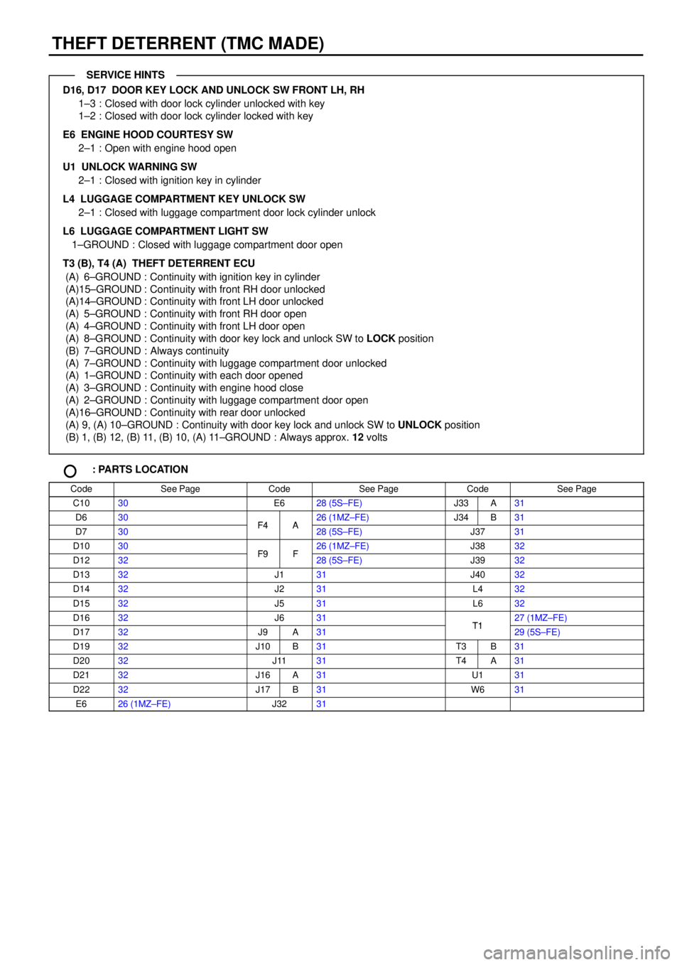
THEFT DETERRENT (TMC MADE)
D16, D17 DOOR KEY LOCK AND UNLOCK SW FRONT LH, RH
1±3 : Closed with door lock cylinder unlocked with key
1±2 : Closed with door lock cylinder locked with key
E6 ENGINE HOOD COURTESY SW
2±1 : Open with engine hood open
U1 UNLOCK WARNING SW
2±1 : Closed with ignition key in cylinder
L4 LUGGAGE COMPARTMENT KEY UNLOCK SW
2±1 : Closed with luggage compartment door lock cylinder unlock
L6 LUGGAGE COMPARTMENT LIGHT SW
1±GROUND : Closed with luggage compartment door open
T3 (B), T4 (A) THEFT DETERRENT ECU
(A) 6±GROUND : Continuity with ignition key in cylinder
(A)15±GROUND : Continuity with front RH door unlocked
(A)14±GROUND : Continuity with front LH door unlocked
(A) 5±GROUND : Continuity with front RH door open
(A) 4±GROUND : Continuity with front LH door open
(A) 8±GROUND : Continuity with door key lock and unlock SW to LOCK position
(B) 7±GROUND : Always continuity
(A) 7±GROUND : Continuity with luggage compartment door unlocked
(A) 1±GROUND : Continuity with each door opened
(A) 3±GROUND : Continuity with engine hood close
(A) 2±GROUND : Continuity with luggage compartment door open
(A)16±GROUND : Continuity with rear door unlocked
(A) 9, (A) 10±GROUND : Continuity with door key lock and unlock SW to UNLOCK position
(B) 1, (B) 12, (B) 11, (B) 10, (A) 11±GROUND : Always approx. 12 volts
: PARTS LOCATION
CodeSee PageCodeSee PageCodeSee Page
C1030E628 (5S±FE)J33A31
D630F4A26 (1MZ±FE)J34B31
D730F4A28 (5S±FE)J3731
D1030F9F26 (1MZ±FE)J3832
D1232F9F28 (5S±FE)J3932
D1332J131J4032
D1432J231L432
D1532J531L632
D1632J631T127 (1MZ±FE)
D1732J9A31T129 (5S±FE)
D1932J10B31T3B31
D2032J1131T4A31
D2132J16A31U131
D2232J17B31W631
E626 (1MZ±FE)J3231
SERVICE HINTS
Page 4415 of 4592
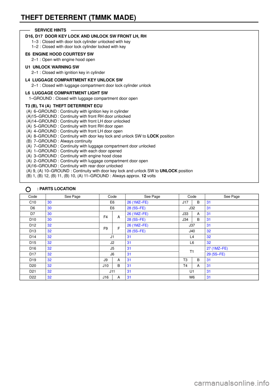
THEFT DETERRENT (TMMK MADE)
D16, D17 DOOR KEY LOCK AND UNLOCK SW FRONT LH, RH
1±3 : Closed with door lock cylinder unlocked with key
1±2 : Closed with door lock cylinder locked with key
E6 ENGINE HOOD COURTESY SW
2±1 : Open with engine hood open
U1 UNLOCK WARNING SW
2±1 : Closed with ignition key in cylinder
L4 LUGGAGE COMPARTMENT KEY UNLOCK SW
2±1 : Closed with luggage compartment door lock cylinder unlock
L6 LUGGAGE COMPARTMENT LIGHT SW
1±GROUND : Closed with luggage compartment door open
T3 (B), T4 (A) THEFT DETERRENT ECU
(A) 6±GROUND : Continuity with ignition key in cylinder
(A)15±GROUND : Continuity with front RH door unlocked
(A)14±GROUND : Continuity with front LH door unlocked
(A) 5±GROUND : Continuity with front RH door open
(A) 4±GROUND : Continuity with front LH door open
(A) 8±GROUND : Continuity with door key lock and unlock SW to LOCK position
(B) 7±GROUND : Always continuity
(A) 7±GROUND : Continuity with luggage compartment door unlocked
(A) 1±GROUND : Continuity with each door opened
(A) 3±GROUND : Continuity with engine hood close
(A) 2±GROUND : Continuity with luggage compartment door open
(A)16±GROUND : Continuity with rear door unlocked
(A) 9, (A) 10±GROUND : Continuity with door key lock and unlock SW to UNLOCK position
(B) 1, (B) 12, (B) 11, (B) 10, (A) 11±GROUND : Always approx. 12 volts
: PARTS LOCATION
CodeSee PageCodeSee PageCodeSee Page
C1030E626 (1MZ±FE)J17B31
D630E628 (5S±FE)J3231
D730F4A26 (1MZ±FE)J33A31
D1030F4A28 (5S±FE)J34B31
D1232F9F26 (1MZ±FE)J3731
D1332F9F28 (5S±FE)J4032
D1432J131L432
D1532J231L632
D1632J531T127 (1MZ±FE)
D1732J631T129 (5S±FE)
D1932J9A31T3B31
D2032J10B31T4A31
D2132J1131U131
D2232J16A31W631
SERVICE HINTS
Page 4420 of 4592
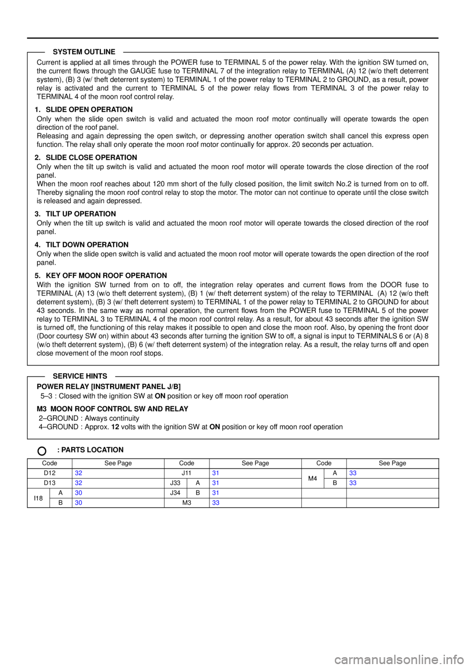
Current is applied at all times through the POWER fuse to TERMINAL 5 of the power relay. With the ignition SW turned on,
the current flows through the GAUGE fuse to TERMINAL 7 of the integration relay to TERMINAL (A) 12 (w/o theft deterrent
system), (B) 3 (w/ theft deterrent system) to TERMINAL 1 of the power relay to TERMINAL 2 to GROUND, as a result, power
relay is activated and the current to TERMINAL 5 of the power relay flows from TERMINAL 3 of the power relay to
TERMINAL 4 of the moon roof control relay.
1. SLIDE OPEN OPERATION
Only when the slide open switch is valid and actuated the moon roof motor continually will operate towards the open
direction of the roof panel.
Releasing and again depressing the open switch, or depressing another operation switch shall cancel this express open
function. The relay shall only operate the moon roof motor continually for approx. 20 seconds per actuation.
2. SLIDE CLOSE OPERATION
Only when the tilt up switch is valid and actuated the moon roof motor will operate towards the close direction of the roof
panel.
When the moon roof reaches about 120 mm short of the fully closed position, the limit switch No.2 is turned from on to off.
Thereby signaling the moon roof control relay to stop the motor. The motor can not continue to operate until the close switch
is released and again depressed.
3. TILT UP OPERATION
Only when the tilt up switch is valid and actuated the moon roof motor will operate towards the closed direction of the roof
panel.
4. TILT DOWN OPERATION
Only when the slide open switch is valid and actuated the moon roof motor will operate towards the open direction of the roof
panel.
5. KEY OFF MOON ROOF OPERATION
With the ignition SW turned from on to off, the integration relay operates and current flows from the DOOR fuse to
TERMINAL (A) 13 (w/o theft deterrent system), (B) 1 (w/ theft deterrent system) of the relay to TERMINAL (A) 12 (w/o theft
deterrent system), (B) 3 (w/ theft deterrent system) to TERMINAL 1 of the power relay to TERMINAL 2 to GROUND for about
43 seconds. In the same way as normal operation, the current flows from the POWER fuse to TERMINAL 5 of the power
relay to TERMINAL 3 to TERMINAL 4 of the moon roof control relay. As a result, for about 43 seconds after the ignition SW
is turned off, the functioning of this relay makes it possible to open and close the moon roof. Also, by opening the front door
(Door courtesy SW on) within about 43 seconds after turning the ignition SW to off, a signal is input to TERMINALS 6 or (A) 8
(w/o theft deterrent system), (B) 6 (w/ theft deterrent system) of the integration relay. As a result, the relay turns off and open
close movement of the moon roof stops.
POWER RELAY [INSTRUMENT PANEL J/B]
5±3 : Closed with the ignition SW at ON position or key off moon roof operation
M3 MOON ROOF CONTROL SW AND RELAY
2±GROUND : Always continuity
4±GROUND : Approx. 12 volts with the ignition SW at ON position or key off moon roof operation
: PARTS LOCATION
CodeSee PageCodeSee PageCodeSee Page
D1232J1131M4A33
D1332J33A31M4B33
I18A30J34B31I18B30M333
SYSTEM OUTLINE
SERVICE HINTS