1999 SUBARU LEGACY wheel torque
[x] Cancel search: wheel torquePage 816 of 1456
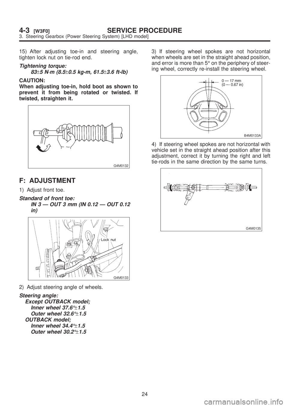
15) After adjusting toe-in and steering angle,
tighten lock nut on tie-rod end.
Tightening torque:
83
±5 N´m (8.5±0.5 kg-m, 61.5±3.6 ft-lb)
CAUTION:
When adjusting toe-in, hold boot as shown to
prevent it from being rotated or twisted. If
twisted, straighten it.
G4M0132
F: ADJUSTMENT
1) Adjust front toe.
Standard of front toe:
IN 3 Ð OUT 3 mm (IN 0.12 Ð OUT 0.12
in)
G4M0133
2) Adjust steering angle of wheels.
Steering angle:
Except OUTBACK model;
Inner wheel 37.6É
±1.5
Outer wheel 32.6É
±1.5
OUTBACK model;
Inner wheel 34.4É
±1.5
Outer wheel 30.2É
±1.5
3) If steering wheel spokes are not horizontal
when wheels are set in the straight ahead position,
and error is more than 5É on the periphery of steer-
ing wheel, correctly re-install the steering wheel.
B4M0133A
4) If steering wheel spokes are not horizontal with
vehicle set in the straight ahead position after this
adjustment, correct it by turning the right and left
tie-rods in the same direction by the same turns.
G4M0135
24
4-3[W3F0]SERVICE PROCEDURE
3. Steering Gearbox (Power Steering System) [LHD model]
Page 844 of 1456
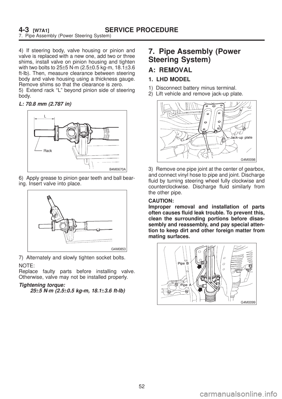
4) If steering body, valve housing or pinion and
valve is replaced with a new one, add two or three
shims, install valve on pinion housing and tighten
with two bolts to 25±5 N´m (2.5±0.5 kg-m, 18.1±3.6
ft-lb). Then, measure clearance between steering
body and valve housing using a thickness gauge.
Remove shims so that the clearance is zero.
5) Extend rack ªLº beyond pinion side of steering
body.
L: 70.8 mm (2.787 in)
B4M0670A
6) Apply grease to pinion gear teeth and ball bear-
ing. Insert valve into place.
G4M0853
7) Alternately and slowly tighten socket bolts.
NOTE:
Replace faulty parts before installing valve.
Otherwise, valve may not be installed properly.
Tightening torque:
25
±5 N´m (2.5±0.5 kg-m, 18.1±3.6 ft-lb)
7. Pipe Assembly (Power
Steering System)
A: REMOVAL
1. LHD MODEL
1) Disconnect battery minus terminal.
2) Lift vehicle and remove jack-up plate.
G4M0098
3) Remove one pipe joint at the center of gearbox,
and connect vinyl hose to pipe and joint. Discharge
fluid by turning steering wheel fully clockwise and
counterclockwise. Discharge fluid similarly from
the other pipe.
CAUTION:
Improper removal and installation of parts
often causes fluid leak trouble. To prevent this,
clean the surrounding portions before disas-
sembly and reassembly, and pay special atten-
tion to keep dirt and other foreign matter from
mating surfaces.
G4M0099
52
4-3[W7A1]SERVICE PROCEDURE
7. Pipe Assembly (Power Steering System)
Page 845 of 1456
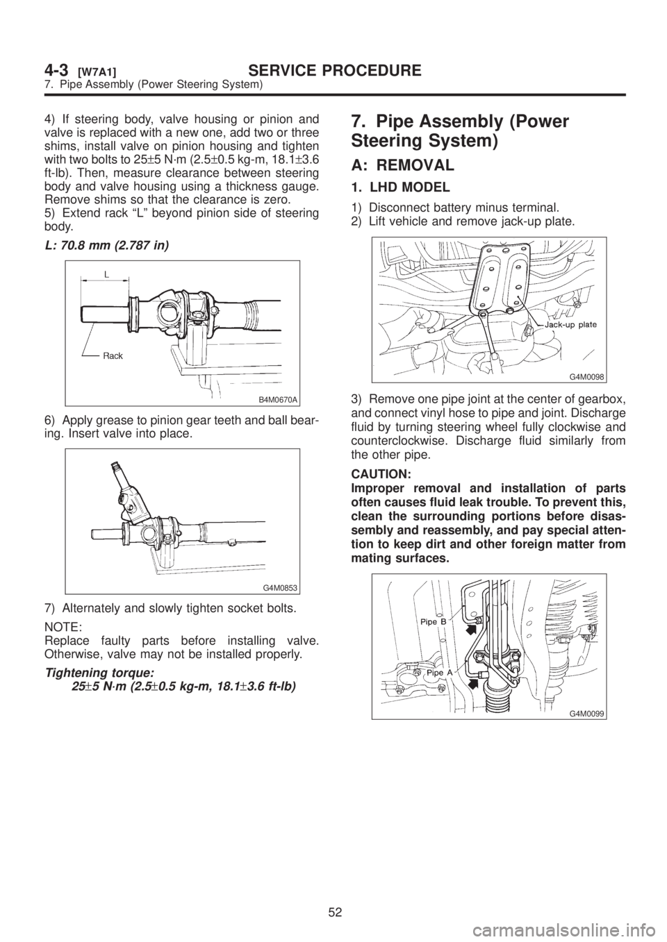
4) If steering body, valve housing or pinion and
valve is replaced with a new one, add two or three
shims, install valve on pinion housing and tighten
with two bolts to 25±5 N´m (2.5±0.5 kg-m, 18.1±3.6
ft-lb). Then, measure clearance between steering
body and valve housing using a thickness gauge.
Remove shims so that the clearance is zero.
5) Extend rack ªLº beyond pinion side of steering
body.
L: 70.8 mm (2.787 in)
B4M0670A
6) Apply grease to pinion gear teeth and ball bear-
ing. Insert valve into place.
G4M0853
7) Alternately and slowly tighten socket bolts.
NOTE:
Replace faulty parts before installing valve.
Otherwise, valve may not be installed properly.
Tightening torque:
25
±5 N´m (2.5±0.5 kg-m, 18.1±3.6 ft-lb)
7. Pipe Assembly (Power
Steering System)
A: REMOVAL
1. LHD MODEL
1) Disconnect battery minus terminal.
2) Lift vehicle and remove jack-up plate.
G4M0098
3) Remove one pipe joint at the center of gearbox,
and connect vinyl hose to pipe and joint. Discharge
fluid by turning steering wheel fully clockwise and
counterclockwise. Discharge fluid similarly from
the other pipe.
CAUTION:
Improper removal and installation of parts
often causes fluid leak trouble. To prevent this,
clean the surrounding portions before disas-
sembly and reassembly, and pay special atten-
tion to keep dirt and other foreign matter from
mating surfaces.
G4M0099
52
4-3[W7A1]SERVICE PROCEDURE
7. Pipe Assembly (Power Steering System)
Page 860 of 1456
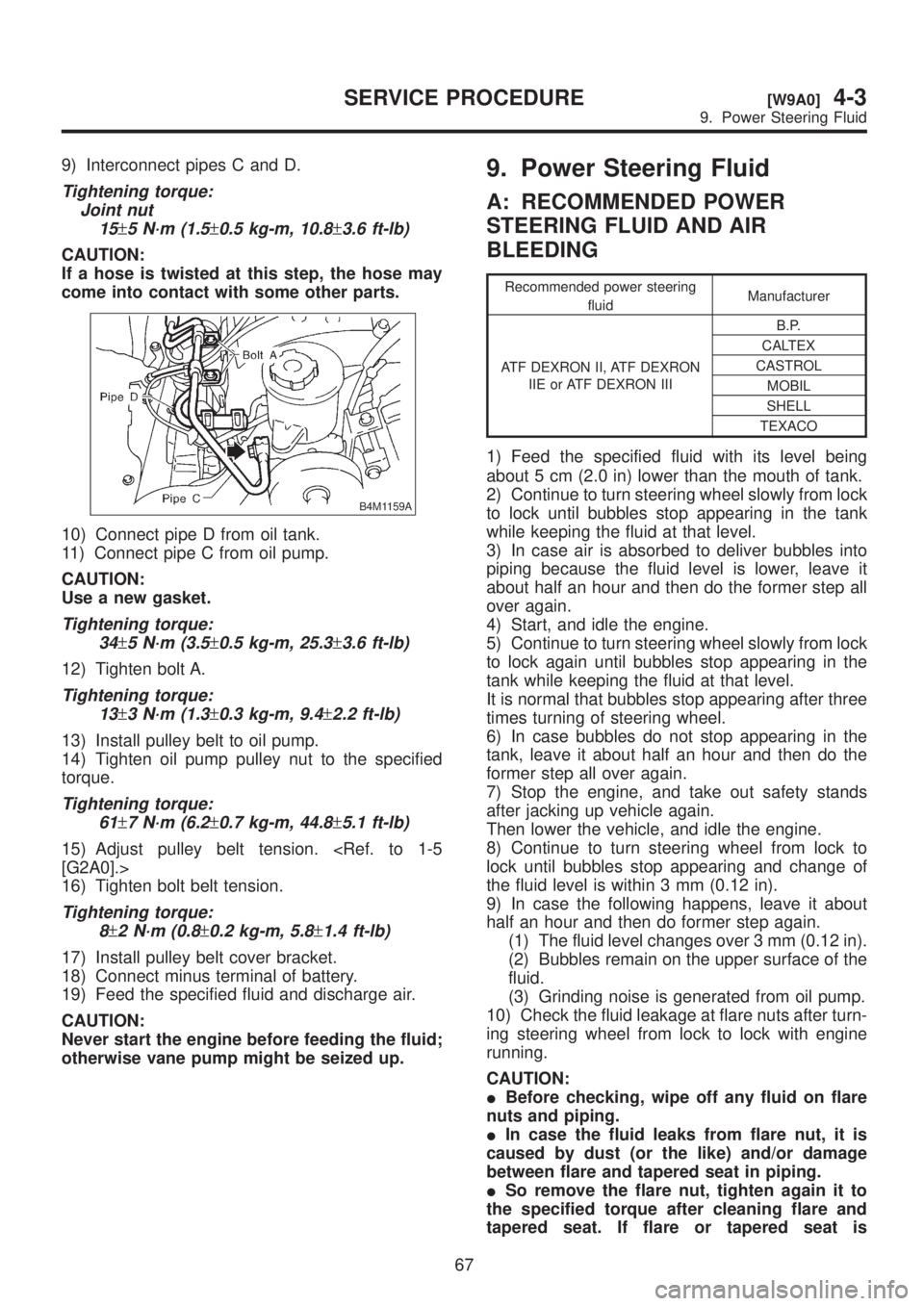
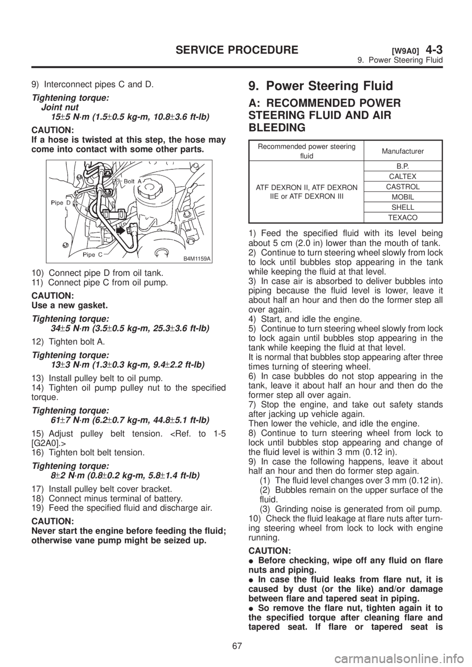
9) Interconnect pipes C and D.
Tightening torque:
Joint nut
15
±5 N´m (1.5±0.5 kg-m, 10.8±3.6 ft-lb)
CAUTION:
If a hose is twisted at this step, the hose may
come into contact with some other parts.
B4M1159A
10) Connect pipe D from oil tank.
11) Connect pipe C from oil pump.
CAUTION:
Use a new gasket.
Tightening torque:
34
±5 N´m (3.5±0.5 kg-m, 25.3±3.6 ft-lb)
12) Tighten bolt A.
Tightening torque:
13
±3 N´m (1.3±0.3 kg-m, 9.4±2.2 ft-lb)
13) Install pulley belt to oil pump.
14) Tighten oil pump pulley nut to the specified
torque.
Tightening torque:
61
±7 N´m (6.2±0.7 kg-m, 44.8±5.1 ft-lb)
15) Adjust pulley belt tension.
16) Tighten bolt belt tension.
Tightening torque:
8
±2 N´m (0.8±0.2 kg-m, 5.8±1.4 ft-lb)
17) Install pulley belt cover bracket.
18) Connect minus terminal of battery.
19) Feed the specified fluid and discharge air.
CAUTION:
Never start the engine before feeding the fluid;
otherwise vane pump might be seized up.
9. Power Steering Fluid
A: RECOMMENDED POWER
STEERING FLUID AND AIR
BLEEDING
Recommended power steering
fluidManufacturer
ATF DEXRON II, ATF DEXRON
IIE or ATF DEXRON IIIB.P.
CALTEX
CASTROL
MOBIL
SHELL
TEXACO
1) Feed the specified fluid with its level being
about 5 cm (2.0 in) lower than the mouth of tank.
2) Continue to turn steering wheel slowly from lock
to lock until bubbles stop appearing in the tank
while keeping the fluid at that level.
3) In case air is absorbed to deliver bubbles into
piping because the fluid level is lower, leave it
about half an hour and then do the former step all
over again.
4) Start, and idle the engine.
5) Continue to turn steering wheel slowly from lock
to lock again until bubbles stop appearing in the
tank while keeping the fluid at that level.
It is normal that bubbles stop appearing after three
times turning of steering wheel.
6) In case bubbles do not stop appearing in the
tank, leave it about half an hour and then do the
former step all over again.
7) Stop the engine, and take out safety stands
after jacking up vehicle again.
Then lower the vehicle, and idle the engine.
8) Continue to turn steering wheel from lock to
lock until bubbles stop appearing and change of
the fluid level is within 3 mm (0.12 in).
9) In case the following happens, leave it about
half an hour and then do former step again.
(1) The fluid level changes over 3 mm (0.12 in).
(2) Bubbles remain on the upper surface of the
fluid.
(3) Grinding noise is generated from oil pump.
10) Check the fluid leakage at flare nuts after turn-
ing steering wheel from lock to lock with engine
running.
CAUTION:
IBefore checking, wipe off any fluid on flare
nuts and piping.
IIn case the fluid leaks from flare nut, it is
caused by dust (or the like) and/or damage
between flare and tapered seat in piping.
ISo remove the flare nut, tighten again it to
the specified torque after cleaning flare and
tapered seat. If flare or tapered seat is
67
[W9A0]4-3SERVICE PROCEDURE
9. Power Steering Fluid
Page 861 of 1456
9) Interconnect pipes C and D.
Tightening torque:
Joint nut
15
±5 N´m (1.5±0.5 kg-m, 10.8±3.6 ft-lb)
CAUTION:
If a hose is twisted at this step, the hose may
come into contact with some other parts.
B4M1159A
10) Connect pipe D from oil tank.
11) Connect pipe C from oil pump.
CAUTION:
Use a new gasket.
Tightening torque:
34
±5 N´m (3.5±0.5 kg-m, 25.3±3.6 ft-lb)
12) Tighten bolt A.
Tightening torque:
13
±3 N´m (1.3±0.3 kg-m, 9.4±2.2 ft-lb)
13) Install pulley belt to oil pump.
14) Tighten oil pump pulley nut to the specified
torque.
Tightening torque:
61
±7 N´m (6.2±0.7 kg-m, 44.8±5.1 ft-lb)
15) Adjust pulley belt tension.
16) Tighten bolt belt tension.
Tightening torque:
8
±2 N´m (0.8±0.2 kg-m, 5.8±1.4 ft-lb)
17) Install pulley belt cover bracket.
18) Connect minus terminal of battery.
19) Feed the specified fluid and discharge air.
CAUTION:
Never start the engine before feeding the fluid;
otherwise vane pump might be seized up.
9. Power Steering Fluid
A: RECOMMENDED POWER
STEERING FLUID AND AIR
BLEEDING
Recommended power steering
fluidManufacturer
ATF DEXRON II, ATF DEXRON
IIE or ATF DEXRON IIIB.P.
CALTEX
CASTROL
MOBIL
SHELL
TEXACO
1) Feed the specified fluid with its level being
about 5 cm (2.0 in) lower than the mouth of tank.
2) Continue to turn steering wheel slowly from lock
to lock until bubbles stop appearing in the tank
while keeping the fluid at that level.
3) In case air is absorbed to deliver bubbles into
piping because the fluid level is lower, leave it
about half an hour and then do the former step all
over again.
4) Start, and idle the engine.
5) Continue to turn steering wheel slowly from lock
to lock again until bubbles stop appearing in the
tank while keeping the fluid at that level.
It is normal that bubbles stop appearing after three
times turning of steering wheel.
6) In case bubbles do not stop appearing in the
tank, leave it about half an hour and then do the
former step all over again.
7) Stop the engine, and take out safety stands
after jacking up vehicle again.
Then lower the vehicle, and idle the engine.
8) Continue to turn steering wheel from lock to
lock until bubbles stop appearing and change of
the fluid level is within 3 mm (0.12 in).
9) In case the following happens, leave it about
half an hour and then do former step again.
(1) The fluid level changes over 3 mm (0.12 in).
(2) Bubbles remain on the upper surface of the
fluid.
(3) Grinding noise is generated from oil pump.
10) Check the fluid leakage at flare nuts after turn-
ing steering wheel from lock to lock with engine
running.
CAUTION:
IBefore checking, wipe off any fluid on flare
nuts and piping.
IIn case the fluid leaks from flare nut, it is
caused by dust (or the like) and/or damage
between flare and tapered seat in piping.
ISo remove the flare nut, tighten again it to
the specified torque after cleaning flare and
tapered seat. If flare or tapered seat is
67
[W9A0]4-3SERVICE PROCEDURE
9. Power Steering Fluid
Page 869 of 1456
![SUBARU LEGACY 1999 Service Repair Manual Trouble Possible cause Corrective action
Rattling noise (intermittent)
While engine is running.Interference with adjacent parts Check clearance.
Correct if necessary.
<Ref. to 4-3 [K1F0].>
Loosened in SUBARU LEGACY 1999 Service Repair Manual Trouble Possible cause Corrective action
Rattling noise (intermittent)
While engine is running.Interference with adjacent parts Check clearance.
Correct if necessary.
<Ref. to 4-3 [K1F0].>
Loosened in](/manual-img/17/57435/w960_57435-868.png)
Trouble Possible cause Corrective action
Rattling noise (intermittent)
While engine is running.Interference with adjacent parts Check clearance.
Correct if necessary.
Loosened installation of oil pump, oil tank, pump bracket, gear-
box or crossmemberRetighten.
Loosened installation of oil pump pulley or other pulley(s) Retighten.
Loosened linkage or play of steering or suspension
Loosened tightening of joint or steering columnRetighten or replace.
Sound generates from the inside of gearbox or oil pump. Replace the gearbox or oil
pump.
Knocking
When turning steering wheel
in both direction with small
angle repeatedly at engine
ON or OFF.Excessive backlash
Loosened lock nut for adjusting backlashAdjust and retighten.
Loosened tightening or play of tie-rod, tie-rod end Retighten or replace.
Grinding noise (continuous)
While engine is running.Vane pump aeration Inspect and retighten fluid line
connection.
Refill fluid and vent air.
Vane pump seizing Replace oil pump.
Pulley bearing seizing of oil pump Replace oil pump.
Folded hose, flat pipe Replace.
Squeal, squeak (intermittent
or continuous)
While engine is running.Maladjustment of pulley belt
Damaged or charged pulley belt
Unequal length of pulley beltsAdjust or replace.
(Replace two belts as a set.)
Run out or soilage of V-groove surface of oil pump pulley Clean or replace.
Sizzling noise (continuous)
While engine is running.Fluid aeration Fix wrong part causing aera-
tion.
Replace fluid and vent air.
Damaged pipe of gearbox Replace pipe.
Abnormal inside of hose or pipe
Flat hose or pipeRectify or replace.
Abnormal inside of oil tank Replace.
Removed oil tank cap Install cap.
Whistle (continuous)
While engine is running.Abnormal pipe of gearbox or abnormal inside of hose Replace bad parts of gearbox
or hose.
Whine or growl (continuous or
intermittent)
While engine is running with/
without steering turned.Loosened installation of oil pump, oil pump bracket Retighten.
Abnormal inside of oil pump, hose Replace oil pump, hose, if the
noise can be heard when run-
ning as well as stand still.
Torque converter growl air conditioner compression growl Remove power steering pul-
ley belt and confirm.
Creaking noise (intermittent)
While engine is running with
steering turned.Abnormal inside of gearbox Replace bad parts of gear-
box.
Abnormal bearing for steering shaft Apply grease or replace.
Generates when turning steering wheel with brake (service or
parking) applied.If the noise goes off when
brake is released, it is normal.
Vibration
While engine is running with/
without steering turned.Too low engine speed at start Adjust and instruct custom-
ers.
Vane pump aeration Fix wrong part.
Vent air.
Damaged valve in oil pump, gearbox Replace oil pump, bad parts
of gearbox.
Looseness of play of steering, suspension parts Retighten.
75
[K1E0]4-3DIAGNOSTICS
1. Power Steering
Page 880 of 1456
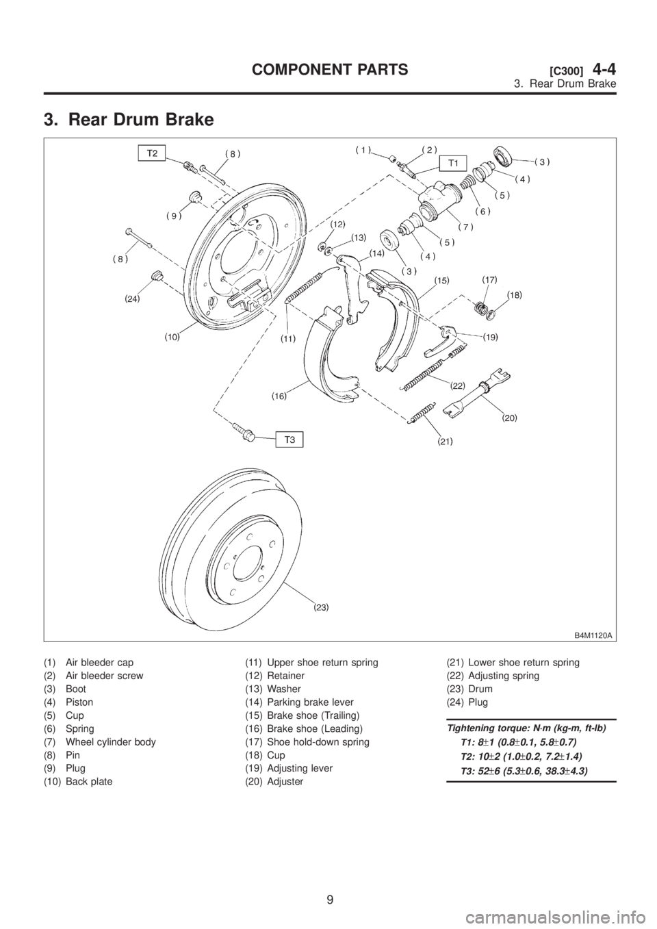
3. Rear Drum Brake
B4M1120A
(1) Air bleeder cap
(2) Air bleeder screw
(3) Boot
(4) Piston
(5) Cup
(6) Spring
(7) Wheel cylinder body
(8) Pin
(9) Plug
(10) Back plate(11) Upper shoe return spring
(12) Retainer
(13) Washer
(14) Parking brake lever
(15) Brake shoe (Trailing)
(16) Brake shoe (Leading)
(17) Shoe hold-down spring
(18) Cup
(19) Adjusting lever
(20) Adjuster(21) Lower shoe return spring
(22) Adjusting spring
(23) Drum
(24) Plug
Tightening torque: N´m (kg-m, ft-lb)
T1:
8±1 (0.8±0.1, 5.8±0.7)
T2:10±2 (1.0±0.2, 7.2±1.4)
T3:52±6 (5.3±0.6, 38.3±4.3)
9
[C300]4-4COMPONENT PARTS
3. Rear Drum Brake
Page 895 of 1456
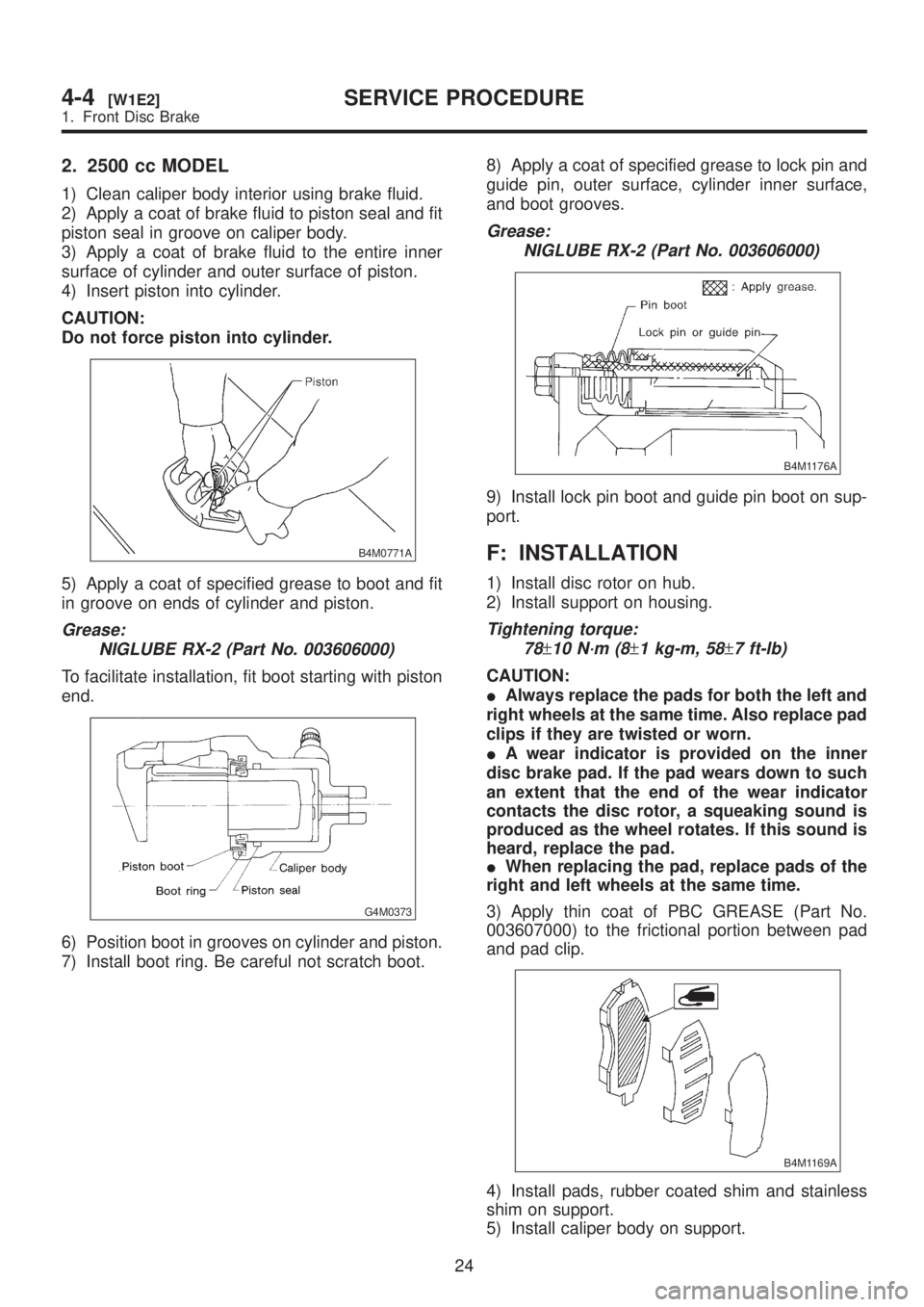
2. 2500 cc MODEL
1) Clean caliper body interior using brake fluid.
2) Apply a coat of brake fluid to piston seal and fit
piston seal in groove on caliper body.
3) Apply a coat of brake fluid to the entire inner
surface of cylinder and outer surface of piston.
4) Insert piston into cylinder.
CAUTION:
Do not force piston into cylinder.
B4M0771A
5) Apply a coat of specified grease to boot and fit
in groove on ends of cylinder and piston.
Grease:
NIGLUBE RX-2 (Part No. 003606000)
To facilitate installation, fit boot starting with piston
end.
G4M0373
6) Position boot in grooves on cylinder and piston.
7) Install boot ring. Be careful not scratch boot.8) Apply a coat of specified grease to lock pin and
guide pin, outer surface, cylinder inner surface,
and boot grooves.
Grease:
NIGLUBE RX-2 (Part No. 003606000)
B4M1176A
9) Install lock pin boot and guide pin boot on sup-
port.
F: INSTALLATION
1) Install disc rotor on hub.
2) Install support on housing.
Tightening torque:
78
±10 N´m (8±1 kg-m, 58±7 ft-lb)
CAUTION:
IAlways replace the pads for both the left and
right wheels at the same time. Also replace pad
clips if they are twisted or worn.
IA wear indicator is provided on the inner
disc brake pad. If the pad wears down to such
an extent that the end of the wear indicator
contacts the disc rotor, a squeaking sound is
produced as the wheel rotates. If this sound is
heard, replace the pad.
IWhen replacing the pad, replace pads of the
right and left wheels at the same time.
3) Apply thin coat of PBC GREASE (Part No.
003607000) to the frictional portion between pad
and pad clip.
B4M1169A
4) Install pads, rubber coated shim and stainless
shim on support.
5) Install caliper body on support.
24
4-4[W1E2]SERVICE PROCEDURE
1. Front Disc Brake