Page 63 of 1456
5. Crankshaft and Piston
B2M1958A
(1) Flywheel (MT)
(2) Bell bearing (MT)
(3) Reinforcement (AT)
(4) Drive plate (AT)
(5) Top ring
(6) Second ring
(7) Oil ring
(8) Piston(9) Piston pin
(10) Circlip
(11) Connecting rod bolt
(12) Connecting rod
(13) Connecting rod bearing
(14) Connecting rod cap
(15) Crankshaft
(16) Woodruff key(17) Crankshaft bearing #1, #3
(18) Crankshaft bearing #2, #4
(19) Crankshaft bearing #5
Tightening torque: N´m (kg-m, ft-lb)
T1:
44±2 (4.5±0.2, 32.5±1.4)
T2:72±3 (7.3±0.3, 52.8±2.2)
10
2-3a[C500]COMPONENT PARTS
5. Crankshaft and Piston
Page 124 of 1456
E: INSTALLATION
1. OIL PUMP AND WATER PUMP
B2M1767B
(1) Baffle plate
(2) Oil strainer
(3) Oil pan
(4) Oil separater cover
(5) Drive plate (AT vehicles only)
(6) Flywheel (MT vehicles only)
(7) Clutch housing cover (MT
vehicles only)(8) Oil pump
(9) Water pump
(10) Water by-pass pipe
(11) Oil filterTightening torque: N´m (kg-m, ft-lb)
T1:
5 (0.5, 3.6)
T2:6.4 (0.65, 4.7)
T3:10 (1.0, 7)
T4:72±3 (7.3±0.3, 52.8±2.2)
T5:First 12±2 (1.2±0.2, 8.7±1.4)
Second 12
±2 (1.2±0.2,
8.7
±1.4)
70
2-3a[W6E1]SERVICE PROCEDURE
6. Cylinder Block
Page 143 of 1456
5. Crankshaft and Piston
B2M1958A
(1) Flywheel (MT vehicles only)
(2) Bell bearing (MT vehicles only)
(3) Reinforcement (AT vehicles only)
(4) Drive plate (AT vehicles only)
(5) Top ring
(6) Second ring
(7) Oil ring
(8) Piston(9) Piston pin
(10) Circlip
(11) Connecting rod bolt
(12) Connecting rod
(13) Connecting rod bearing
(14) Connecting rod cap
(15) Crankshaft
(16) Woodruff key(17) Crankshaft bearing #1, #3
(18) Crankshaft bearing #2, #4
(19) Crankshaft bearing #5
Tightening torque: N´m (kg-m, ft-lb)
T1:
44±2 (4.5±0.2, 32.5±1.4)
T2:72±3 (7.3±0.3, 52.8±2.2)
12
2-3b[C500]COMPONENT PARTS
5. Crankshaft and Piston
Page 199 of 1456
E: INSTALLATION
1. OIL PUMP AND WATER PUMP
B2M1767C
(1) Baffle plate
(2) Oil strainer
(3) Oil pan
(4) Oil separator cover
(5) Drive plate (AT vehicles only)
(6) Flywheel (MT vehicles only)
(7) Clutch housing cover (MT
vehicles only)(8) Oil pump
(9) Water pump
(10) Water by-pass pipe
(11) Oil filterTightening torque: N´m (kg-m, ft-lb)
T1:
5 (0.5, 3.6)
T2:6.4 (0.65, 4.7)
T3:10 (1.0, 7)
T4:72±3 (7.3±0.3, 52.8±2.2)
T5:First 12±2 (1.2±0.2, 8.7±1.4)
Second 12
±2 (1.2±0.2,
8.7
±1.4)
68
2-3b[W5E1]SERVICE PROCEDURE
5. Cylinder Block
Page 216 of 1456
E: INSTALLATION
Installation is in the reverse order of removal.
Observe the following:
1) Apply fluid packing to matching surfaces of oil
pump.
Fluid packing:
THREE BOND 1215 or equivalent
H2M2424A
2) Replace O-ring with a new one.
3) Apply a coat of engine oil to the inside of the oil
seal.
S2M0118A
4) Be careful not to scratch oil seal when installing
oil pump on cylinder block.
5) Position the oil pump, aligning the notched area
with the crankshaft, and push the oil pump straight.
CAUTION:
Make sure the oil seal lip is not folded.
6) Install oil pump.
Tightening torque:
6.4 N´m (0.65 kg-m, 4.7 ft-lb)
S2M0120A
2. Oil Pan and Oil Strainer
A: REMOVAL
1) Disconnect battery ground cable.
G6M0095
2) Remove front wheels.
3) Remove air intake duct and air cleaner assem-
bly. (2200 cc California spec. vehicles)
B2M2771
4) Remove air intake duct and air intake chamber.
(Except 2200 cc California spec. vehicles)
B2M2772
10
2-4[W1E0]SERVICE PROCEDURE
2. Oil Pan and Oil Strainer
Page 217 of 1456
E: INSTALLATION
Installation is in the reverse order of removal.
Observe the following:
1) Apply fluid packing to matching surfaces of oil
pump.
Fluid packing:
THREE BOND 1215 or equivalent
H2M2424A
2) Replace O-ring with a new one.
3) Apply a coat of engine oil to the inside of the oil
seal.
S2M0118A
4) Be careful not to scratch oil seal when installing
oil pump on cylinder block.
5) Position the oil pump, aligning the notched area
with the crankshaft, and push the oil pump straight.
CAUTION:
Make sure the oil seal lip is not folded.
6) Install oil pump.
Tightening torque:
6.4 N´m (0.65 kg-m, 4.7 ft-lb)
S2M0120A
2. Oil Pan and Oil Strainer
A: REMOVAL
1) Disconnect battery ground cable.
G6M0095
2) Remove front wheels.
3) Remove air intake duct and air cleaner assem-
bly. (2200 cc California spec. vehicles)
B2M2771
4) Remove air intake duct and air intake chamber.
(Except 2200 cc California spec. vehicles)
B2M2772
10
2-4[W1E0]SERVICE PROCEDURE
2. Oil Pan and Oil Strainer
Page 413 of 1456
B: HYDRAULIC APPLICATION TYPE
B2M1890A
(1) Operating cylinder
(2) Washer
(3) Clutch hose
(4) Bracket
(5) Clamp
(6) Pipe
(7) Master cylinder ASSY
(8) Clevis pin
(9) Snap pin(10) Lever
(11) Clutch release lever sealing
(12) Retainer spring
(13) Pivot
(14) Release lever
(15) Clip
(16) Release bearing
(17) Clutch cover
(18) Clutch disc(19) Flywheel
Tightening torque: N´m (kg-m, ft-lb)
T1:
15.7±1.5 (1.6±0.15, 11.6±1.1)
T2:18±3 (1.8±0.3, 13.0±2.2)
T3:37±3 (3.8±0.3, 27.5±2.2)
4
2-10[C1B0]COMPONENT PARTS
1. Clutch System
Page 421 of 1456

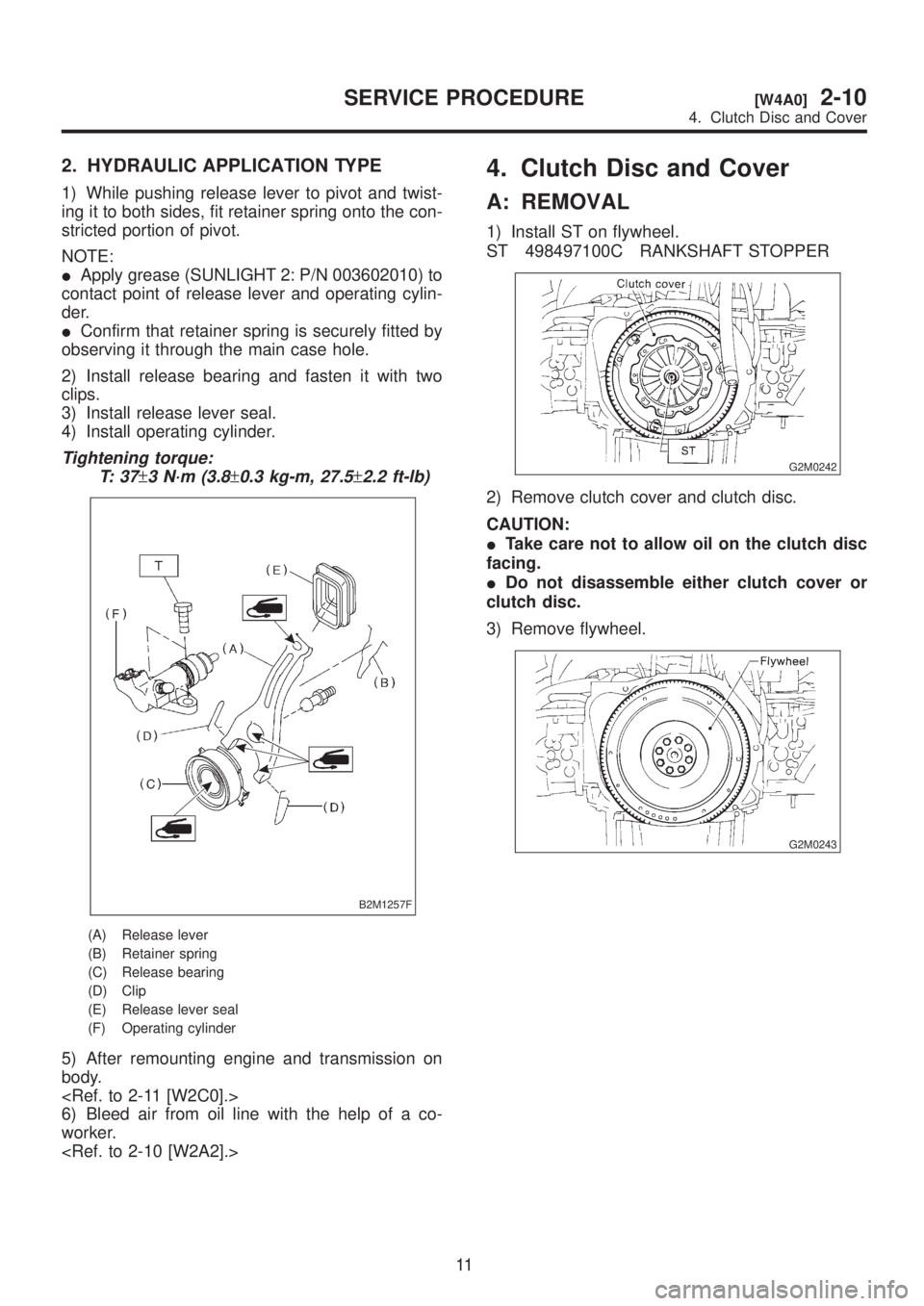
2. HYDRAULIC APPLICATION TYPE
1) While pushing release lever to pivot and twist-
ing it to both sides, fit retainer spring onto the con-
stricted portion of pivot.
NOTE:
IApply grease (SUNLIGHT 2: P/N 003602010) to
contact point of release lever and operating cylin-
der.
IConfirm that retainer spring is securely fitted by
observing it through the main case hole.
2) Install release bearing and fasten it with two
clips.
3) Install release lever seal.
4) Install operating cylinder.
Tightening torque:
T: 3 7
±3 N´m (3.8±0.3 kg-m, 27.5±2.2 ft-lb)
B2M1257F
(A) Release lever
(B) Retainer spring
(C) Release bearing
(D) Clip
(E) Release lever seal
(F) Operating cylinder
5) After remounting engine and transmission on
body.
6) Bleed air from oil line with the help of a co-
worker.
4. Clutch Disc and Cover
A: REMOVAL
1) Install ST on flywheel.
ST 498497100C RANKSHAFT STOPPER
G2M0242
2) Remove clutch cover and clutch disc.
CAUTION:
ITake care not to allow oil on the clutch disc
facing.
IDo not disassemble either clutch cover or
clutch disc.
3) Remove flywheel.
G2M0243
11
[W4A0]2-10SERVICE PROCEDURE
4. Clutch Disc and Cover