Page 422 of 1456

2. HYDRAULIC APPLICATION TYPE
1) While pushing release lever to pivot and twist-
ing it to both sides, fit retainer spring onto the con-
stricted portion of pivot.
NOTE:
IApply grease (SUNLIGHT 2: P/N 003602010) to
contact point of release lever and operating cylin-
der.
IConfirm that retainer spring is securely fitted by
observing it through the main case hole.
2) Install release bearing and fasten it with two
clips.
3) Install release lever seal.
4) Install operating cylinder.
Tightening torque:
T: 3 7
±3 N´m (3.8±0.3 kg-m, 27.5±2.2 ft-lb)
B2M1257F
(A) Release lever
(B) Retainer spring
(C) Release bearing
(D) Clip
(E) Release lever seal
(F) Operating cylinder
5) After remounting engine and transmission on
body.
6) Bleed air from oil line with the help of a co-
worker.
4. Clutch Disc and Cover
A: REMOVAL
1) Install ST on flywheel.
ST 498497100C RANKSHAFT STOPPER
G2M0242
2) Remove clutch cover and clutch disc.
CAUTION:
ITake care not to allow oil on the clutch disc
facing.
IDo not disassemble either clutch cover or
clutch disc.
3) Remove flywheel.
G2M0243
11
[W4A0]2-10SERVICE PROCEDURE
4. Clutch Disc and Cover
Page 424 of 1456

3) Damaged or worn disc contact surface of pres-
sure plate.
4) Loose strap plate setting bolt.
5) Worn diaphragm sliding surface.
G2M0249
3. FLYWHEEL
CAUTION:
Since this bearing is grease sealed and is of a
nonlubrication type, do not wash with gasoline
or any solvent.
1) Damage of facing and ring gear
If defective, replace flywheel.
G2M0250
2) Smoothness of rotation
Rotate ball bearing applying pressure in thrust
direction.3) If noise or excessive play is noted, replace ball
bearing as follows:
(1) Drive out ball bearing from flywheel.
(2) Press bearing into flywheel until bearing
end surface is flush with clutch disc contact sur-
face of flywheel. Do not press inner race.
ST 899754112 SNAP RING PRESS
H2M1563A
C: INSTALLATION
1) Install flywheel and ST.
ST 498497100 CRANKSHAFT STOPPER
B2M0332A
2) Tighten the flywheel attaching bolts to the
specified torque.
NOTE:
Tighten flywheel installing bolts gradually. Each
bolt should be tightened to the specified torque in
a crisscross fashion.
Tightening torque:
72
±3 N´m (7.3±0.3 kg-m, 52.8±2.2 ft-lb)
B2M0331B
13
[W4C0]2-10SERVICE PROCEDURE
4. Clutch Disc and Cover
Page 425 of 1456
3) Insert ST into the clutch disc and install them on
the flywheel by inserting the ST end into the pilot
bearing.
ST 499747100 CLUTCH DISC GUIDE
G2M0253
4) Install clutch cover on flywheel and tighten bolts
to the specified torque.
NOTE:
IWhen installing the clutch cover on the flywheel,
position the clutch cover so that there is a gap of
120É or more between ª0º marks on the flywheel
and clutch cover. (ª0º marks indicate the directions
of residual unbalance.)
INote the front and rear of the clutch disc when
installing.
ITighten clutch cover installing bolts gradually.
Each bolt should be tightened to the specified
torque in a crisscross fashion.
Tightening torque:
15.7
±1.5 N´m (1.6±0.15 kg-m, 11.6±1.1
ft-lb)
5) Remove ST.
ST 499747100 CLUTCH DISC GUIDE
B2M1011A
14
2-10[W4C0]SERVICE PROCEDURE
4. Clutch Disc and Cover
Page 568 of 1456

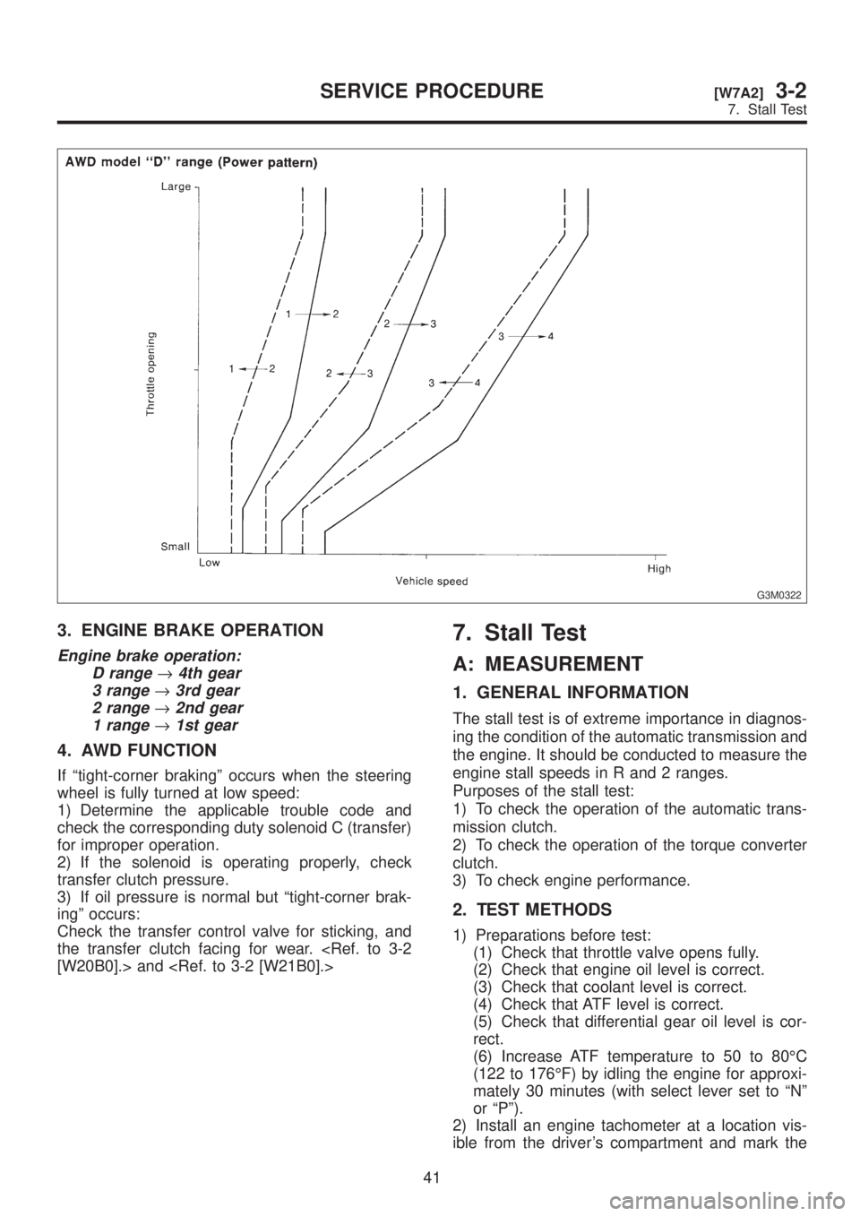
G3M0322
3. ENGINE BRAKE OPERATION
Engine brake operation:
D range
®4th gear
3 range
®3rd gear
2 range
®2nd gear
1 range
®1st gear
4. AWD FUNCTION
If ªtight-corner brakingº occurs when the steering
wheel is fully turned at low speed:
1) Determine the applicable trouble code and
check the corresponding duty solenoid C (transfer)
for improper operation.
2) If the solenoid is operating properly, check
transfer clutch pressure.
3) If oil pressure is normal but ªtight-corner brak-
ingº occurs:
Check the transfer control valve for sticking, and
the transfer clutch facing for wear.
[W20B0].> and
7. Stall Test
A: MEASUREMENT
1. GENERAL INFORMATION
The stall test is of extreme importance in diagnos-
ing the condition of the automatic transmission and
the engine. It should be conducted to measure the
engine stall speeds in R and 2 ranges.
Purposes of the stall test:
1) To check the operation of the automatic trans-
mission clutch.
2) To check the operation of the torque converter
clutch.
3) To check engine performance.
2. TEST METHODS
1) Preparations before test:
(1) Check that throttle valve opens fully.
(2) Check that engine oil level is correct.
(3) Check that coolant level is correct.
(4) Check that ATF level is correct.
(5) Check that differential gear oil level is cor-
rect.
(6) Increase ATF temperature to 50 to 80ÉC
(122 to 176ÉF) by idling the engine for approxi-
mately 30 minutes (with select lever set to ªNº
or ªPº).
2) Install an engine tachometer at a location vis-
ible from the driver's compartment and mark the
41
[W7A2]3-2SERVICE PROCEDURE
7. Stall Test
Page 569 of 1456

G3M0322
3. ENGINE BRAKE OPERATION
Engine brake operation:
D range
®4th gear
3 range
®3rd gear
2 range
®2nd gear
1 range
®1st gear
4. AWD FUNCTION
If ªtight-corner brakingº occurs when the steering
wheel is fully turned at low speed:
1) Determine the applicable trouble code and
check the corresponding duty solenoid C (transfer)
for improper operation.
2) If the solenoid is operating properly, check
transfer clutch pressure.
3) If oil pressure is normal but ªtight-corner brak-
ingº occurs:
Check the transfer control valve for sticking, and
the transfer clutch facing for wear.
[W20B0].> and
7. Stall Test
A: MEASUREMENT
1. GENERAL INFORMATION
The stall test is of extreme importance in diagnos-
ing the condition of the automatic transmission and
the engine. It should be conducted to measure the
engine stall speeds in R and 2 ranges.
Purposes of the stall test:
1) To check the operation of the automatic trans-
mission clutch.
2) To check the operation of the torque converter
clutch.
3) To check engine performance.
2. TEST METHODS
1) Preparations before test:
(1) Check that throttle valve opens fully.
(2) Check that engine oil level is correct.
(3) Check that coolant level is correct.
(4) Check that ATF level is correct.
(5) Check that differential gear oil level is cor-
rect.
(6) Increase ATF temperature to 50 to 80ÉC
(122 to 176ÉF) by idling the engine for approxi-
mately 30 minutes (with select lever set to ªNº
or ªPº).
2) Install an engine tachometer at a location vis-
ible from the driver's compartment and mark the
41
[W7A2]3-2SERVICE PROCEDURE
7. Stall Test
Page 570 of 1456

stall speed range on the tachometer scale.
3) Place the wheel chocks at the front and rear of
all wheels and engage the parking brake.
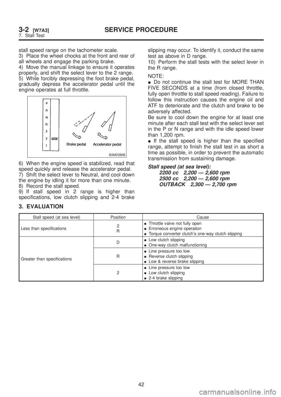
4) Move the manual linkage to ensure it operates
properly, and shift the select lever to the 2 range.
5) While forcibly depressing the foot brake pedal,
gradually depress the accelerator pedal until the
engine operates at full throttle.
B3M0286B
6) When the engine speed is stabilized, read that
speed quickly and release the accelerator pedal.
7) Shift the select lever to Neutral, and cool down
the engine by idling it for more than one minute.
8) Record the stall speed.
9) If stall speed in 2 range is higher than
specifications, low clutch slipping and 2-4 brakeslipping may occur. To identify it, conduct the same
test as above in D range.
10) Perform the stall tests with the select lever in
the R range.
NOTE:
IDo not continue the stall test for MORE THAN
FIVE SECONDS at a time (from closed throttle,
fully open throttle to stall speed reading). Failure to
follow this instruction causes the engine oil and
ATF to deteriorate and the clutch and brake to be
adversely affected.
Be sure to cool down the engine for at least one
minute after each stall test with the select lever set
in the P or N range and with the idle speed lower
than 1,200 rpm.
IIf the stall speed is higher than the specified
range, attempt to finish the stall test in as short a
time as possible, in order to prevent the automatic
transmission from sustaining damage.Stall speed (at sea level):
2200 cc 2,200 Ð 2,600 rpm
2500 cc 2,200 Ð 2,600 rpm
OUTBACK 2,300 Ð 2,700 rpm
3. EVALUATION
Stall speed (at sea level) Position Cause
Less than specifications2
RIThrottle valve not fully open
IErroneous engine operation
ITorque converter clutch's one-way clutch slipping
Greater than specificationsDILow clutch slipping
IOne-way clutch malfunctioning
RILine pressure too low
IReverse clutch slipping
ILow & reverse brake slipping
2ILine pressure too low
ILow clutch slipping
I2-4 brake slipping
42
3-2[W7A3]SERVICE PROCEDURE
7. Stall Test
Page 663 of 1456
2) Align matching marks and connect flange yoke
and rear differential.
Tightening torque:
31
±8 N´m (3.2±0.8 kg-m, 23.1±5.8 ft-lb)
G3M0782
3) Install differential mount front cover.
Tightening torque:
88
±10 N´m (9.0±1.0 kg-m, 65±7 ft-lb)
G3M0022
4) Install front exhaust cover.
5) Install rear exhaust pipe and muffler.
G3M0021
2. Rear Differential
A: ON-CAR SERVICE
1. FRONT OIL SEAL
1) Disconnect ground cable from battery.
2) Move selector lever or gear shift lever to ªNº.
3) Release the parking brake.
4) Remove oil drain plug, and drain gear oil.
B3M0316A
5) Jack-up rear wheels and support the vehicle
body with sturdy racks.
6) Remove propeller shaft from body.
[W1B0].>
CAUTION:
Wrap metal parts with a cloth or rubber mate-
rial to prevent damage from adjacent metal
parts.
S3M0028
7) Remove self-locking nut while holding compan-
ion flange with ST.
ST 498427200 FLANGE WRENCH
G3M0034
14
3-4[W2A1]SERVICE PROCEDURE
2. Rear Differential
Page 664 of 1456
2) Align matching marks and connect flange yoke
and rear differential.
Tightening torque:
31
±8 N´m (3.2±0.8 kg-m, 23.1±5.8 ft-lb)
G3M0782
3) Install differential mount front cover.
Tightening torque:
88
±10 N´m (9.0±1.0 kg-m, 65±7 ft-lb)
G3M0022
4) Install front exhaust cover.
5) Install rear exhaust pipe and muffler.
G3M0021
2. Rear Differential
A: ON-CAR SERVICE
1. FRONT OIL SEAL
1) Disconnect ground cable from battery.
2) Move selector lever or gear shift lever to ªNº.
3) Release the parking brake.
4) Remove oil drain plug, and drain gear oil.
B3M0316A
5) Jack-up rear wheels and support the vehicle
body with sturdy racks.
6) Remove propeller shaft from body.
[W1B0].>
CAUTION:
Wrap metal parts with a cloth or rubber mate-
rial to prevent damage from adjacent metal
parts.
S3M0028
7) Remove self-locking nut while holding compan-
ion flange with ST.
ST 498427200 FLANGE WRENCH
G3M0034
14
3-4[W2A1]SERVICE PROCEDURE
2. Rear Differential