Page 1176 of 1456
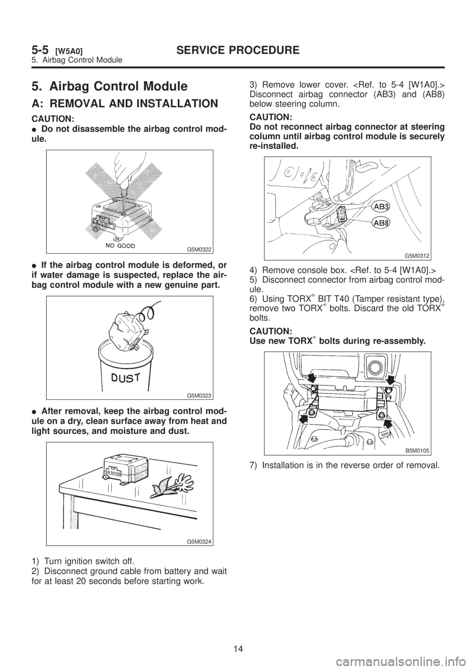
5. Airbag Control Module
A: REMOVAL AND INSTALLATION
CAUTION:
IDo not disassemble the airbag control mod-
ule.
G5M0322
IIf the airbag control module is deformed, or
if water damage is suspected, replace the air-
bag control module with a new genuine part.
G5M0323
IAfter removal, keep the airbag control mod-
ule on a dry, clean surface away from heat and
light sources, and moisture and dust.
G5M0324
1) Turn ignition switch off.
2) Disconnect ground cable from battery and wait
for at least 20 seconds before starting work.3) Remove lower cover.
Disconnect airbag connector (AB3) and (AB8)
below steering column.
CAUTION:
Do not reconnect airbag connector at steering
column until airbag control module is securely
re-installed.
G5M0312
4) Remove console box.
5) Disconnect connector from airbag control mod-
ule.
6) Using TORX
TBIT T40 (Tamper resistant type),
remove two TORXTbolts. Discard the old TORXT
bolts.
CAUTION:
Use new TORX
Tbolts during re-assembly.
B5M0105
7) Installation is in the reverse order of removal.
14
5-5[W5A0]SERVICE PROCEDURE
5. Airbag Control Module
Page 1178 of 1456
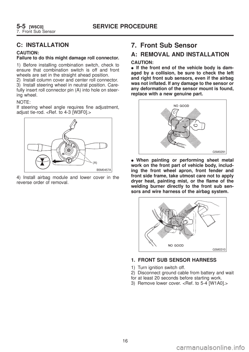
C: INSTALLATION
CAUTION:
Failure to do this might damage roll connector.
1) Before installing combination switch, check to
ensure that combination switch is off and front
wheels are set in the straight ahead position.
2) Install column cover and center roll connector.
3) Install steering wheel in neutral position. Care-
fully insert roll connector pin (A) into hole on steer-
ing wheel.
NOTE:
If steering wheel angle requires fine adjustment,
adjust tie-rod.
B5M0457A
4) Install airbag module and lower cover in the
reverse order of removal.
7. Front Sub Sensor
A: REMOVAL AND INSTALLATION
CAUTION:
IIf the front end of the vehicle body is dam-
aged by a collision, be sure to check the left
and right front sub sensors, even if the airbag
was not inflated. If any damage to the sensor or
any deformation of the sensor mount is found,
replace with a new genuine part.
G5M0291
IWhen painting or performing sheet metal
work on the front part of vehicle body, includ-
ing the front wheel apron, front fender and
front side frame, take utmost care not to apply
dryer heat, painting mist, or the flame of the
welding burner directly to the front sub sen-
sors and wire harness of the airbag system.
G5M0310
1. FRONT SUB SENSOR HARNESS
1) Turn ignition switch off.
2) Disconnect ground cable from battery and wait
for at least 20 seconds before starting work.
3) Remove lower cover.
16
5-5[W6C0]SERVICE PROCEDURE
7. Front Sub Sensor
Page 1179 of 1456
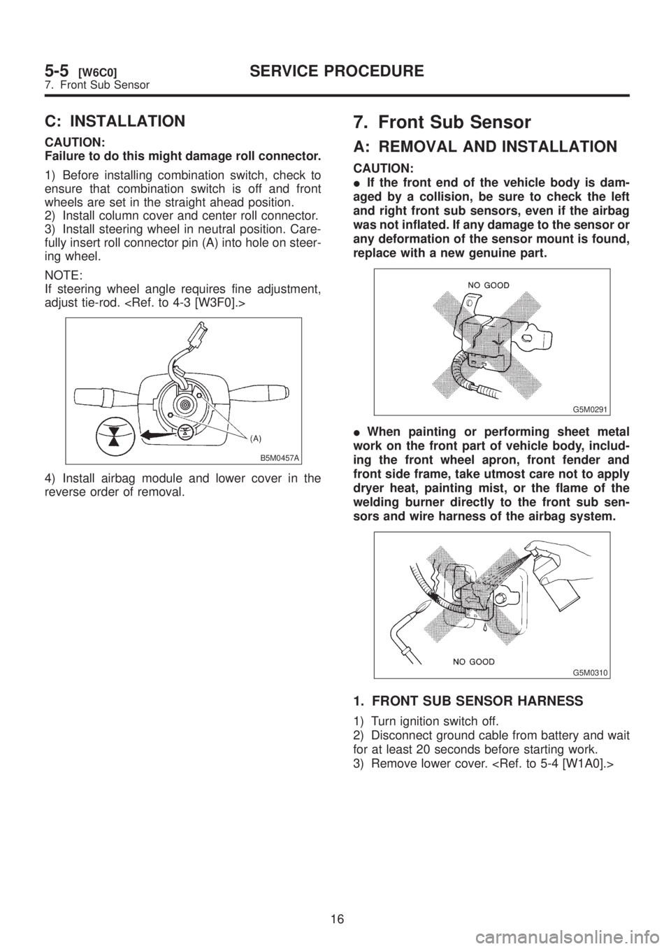
C: INSTALLATION
CAUTION:
Failure to do this might damage roll connector.
1) Before installing combination switch, check to
ensure that combination switch is off and front
wheels are set in the straight ahead position.
2) Install column cover and center roll connector.
3) Install steering wheel in neutral position. Care-
fully insert roll connector pin (A) into hole on steer-
ing wheel.
NOTE:
If steering wheel angle requires fine adjustment,
adjust tie-rod.
B5M0457A
4) Install airbag module and lower cover in the
reverse order of removal.
7. Front Sub Sensor
A: REMOVAL AND INSTALLATION
CAUTION:
IIf the front end of the vehicle body is dam-
aged by a collision, be sure to check the left
and right front sub sensors, even if the airbag
was not inflated. If any damage to the sensor or
any deformation of the sensor mount is found,
replace with a new genuine part.
G5M0291
IWhen painting or performing sheet metal
work on the front part of vehicle body, includ-
ing the front wheel apron, front fender and
front side frame, take utmost care not to apply
dryer heat, painting mist, or the flame of the
welding burner directly to the front sub sen-
sors and wire harness of the airbag system.
G5M0310
1. FRONT SUB SENSOR HARNESS
1) Turn ignition switch off.
2) Disconnect ground cable from battery and wait
for at least 20 seconds before starting work.
3) Remove lower cover.
16
5-5[W6C0]SERVICE PROCEDURE
7. Front Sub Sensor
Page 1181 of 1456
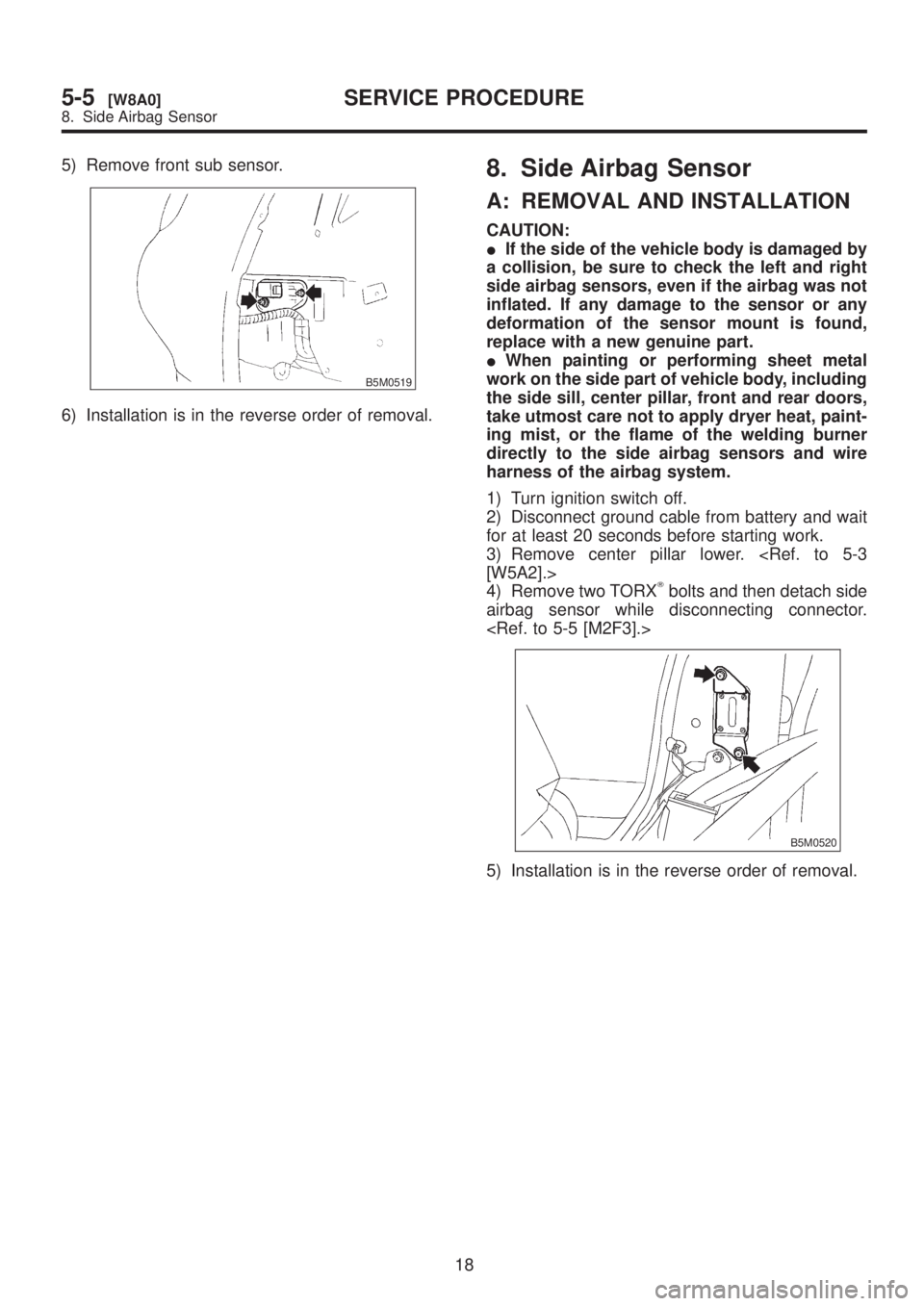
5) Remove front sub sensor.
B5M0519
6) Installation is in the reverse order of removal.
8. Side Airbag Sensor
A: REMOVAL AND INSTALLATION
CAUTION:
IIf the side of the vehicle body is damaged by
a collision, be sure to check the left and right
side airbag sensors, even if the airbag was not
inflated. If any damage to the sensor or any
deformation of the sensor mount is found,
replace with a new genuine part.
IWhen painting or performing sheet metal
work on the side part of vehicle body, including
the side sill, center pillar, front and rear doors,
take utmost care not to apply dryer heat, paint-
ing mist, or the flame of the welding burner
directly to the side airbag sensors and wire
harness of the airbag system.
1) Turn ignition switch off.
2) Disconnect ground cable from battery and wait
for at least 20 seconds before starting work.
3) Remove center pillar lower.
[W5A2].>
4) Remove two TORX
Tbolts and then detach side
airbag sensor while disconnecting connector.
B5M0520
5) Installation is in the reverse order of removal.
18
5-5[W8A0]SERVICE PROCEDURE
8. Side Airbag Sensor
Page 1182 of 1456
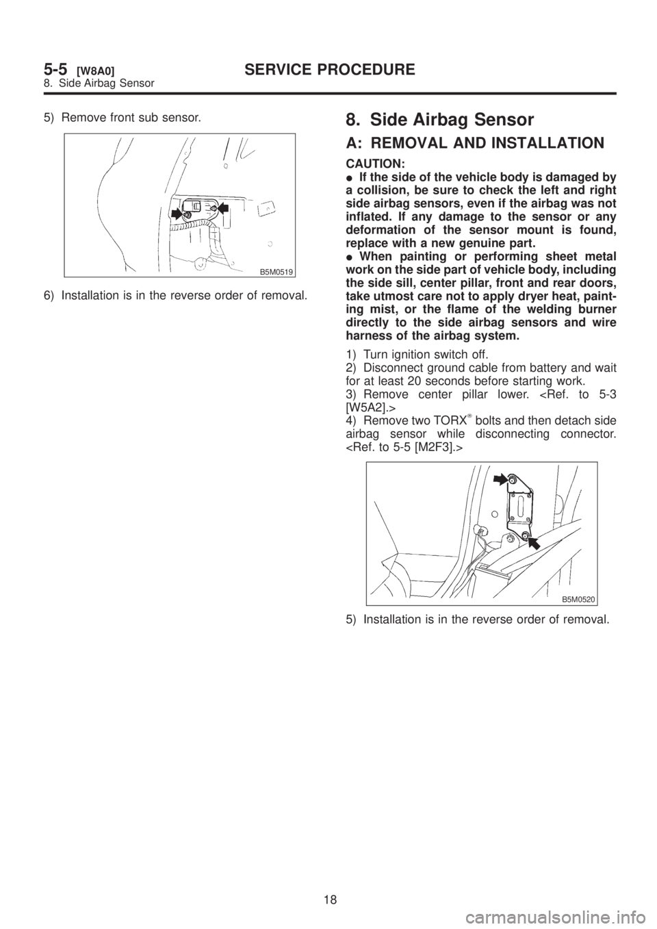
5) Remove front sub sensor.
B5M0519
6) Installation is in the reverse order of removal.
8. Side Airbag Sensor
A: REMOVAL AND INSTALLATION
CAUTION:
IIf the side of the vehicle body is damaged by
a collision, be sure to check the left and right
side airbag sensors, even if the airbag was not
inflated. If any damage to the sensor or any
deformation of the sensor mount is found,
replace with a new genuine part.
IWhen painting or performing sheet metal
work on the side part of vehicle body, including
the side sill, center pillar, front and rear doors,
take utmost care not to apply dryer heat, paint-
ing mist, or the flame of the welding burner
directly to the side airbag sensors and wire
harness of the airbag system.
1) Turn ignition switch off.
2) Disconnect ground cable from battery and wait
for at least 20 seconds before starting work.
3) Remove center pillar lower.
[W5A2].>
4) Remove two TORX
Tbolts and then detach side
airbag sensor while disconnecting connector.
B5M0520
5) Installation is in the reverse order of removal.
18
5-5[W8A0]SERVICE PROCEDURE
8. Side Airbag Sensor
Page 1196 of 1456
2. Generator
A: REMOVAL AND INSTALLATION
1) Disconnect battery ground cable.
B2M1723
2) Disconnect connector and terminal from gen-
erator.
B6M0864
3) Remove V-belt covers.
B6M0865
4) Remove front side V-belt.
G2M0286
5) Remove bolts which install generator onto
bracket.
B6M0866
6) Installation is in the reverse order of removal.
CAUTION:
Check and adjust V-belt tension.
[G2A0].>
B6M0866
B: DISASSEMBLY
1) Heat the portion (A) of rear cover to 50ÉC
(122ÉF) with heater drier.
B6M0476B
15
[W2B0]6-1SERVICE PROCEDURE
2. Generator
Page 1201 of 1456
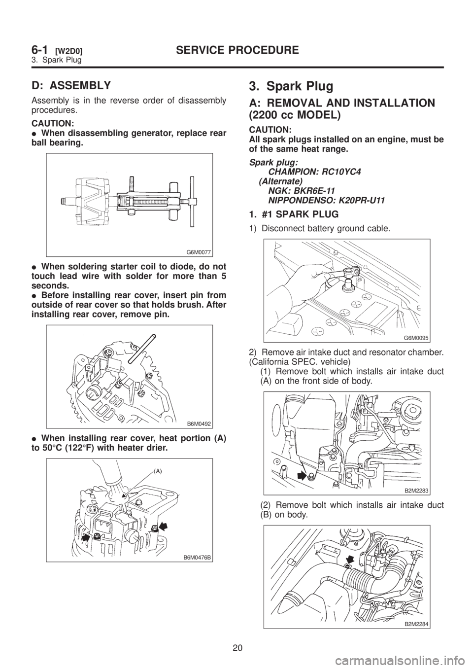
D: ASSEMBLY
Assembly is in the reverse order of disassembly
procedures.
CAUTION:
IWhen disassembling generator, replace rear
ball bearing.
G6M0077
IWhen soldering starter coil to diode, do not
touch lead wire with solder for more than 5
seconds.
IBefore installing rear cover, insert pin from
outside of rear cover so that holds brush. After
installing rear cover, remove pin.
B6M0492
IWhen installing rear cover, heat portion (A)
to 50ÉC (122ÉF) with heater drier.
B6M0476B
3. Spark Plug
A: REMOVAL AND INSTALLATION
(2200 cc MODEL)
CAUTION:
All spark plugs installed on an engine, must be
of the same heat range.
Spark plug:
CHAMPION: RC10YC4
(Alternate)
NGK: BKR6E-11
NIPPONDENSO: K20PR-U11
1. #1 SPARK PLUG
1) Disconnect battery ground cable.
G6M0095
2) Remove air intake duct and resonator chamber.
(California SPEC. vehicle)
(1) Remove bolt which installs air intake duct
(A) on the front side of body.
B2M2283
(2) Remove bolt which installs air intake duct
(B) on body.
B2M2284
20
6-1[W2D0]SERVICE PROCEDURE
3. Spark Plug
Page 1202 of 1456
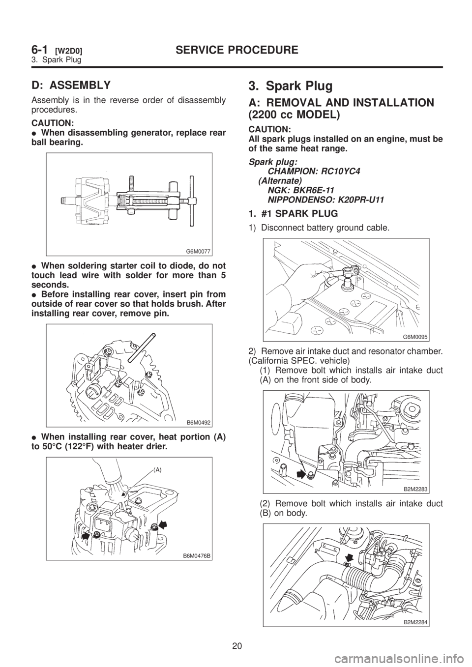
D: ASSEMBLY
Assembly is in the reverse order of disassembly
procedures.
CAUTION:
IWhen disassembling generator, replace rear
ball bearing.
G6M0077
IWhen soldering starter coil to diode, do not
touch lead wire with solder for more than 5
seconds.
IBefore installing rear cover, insert pin from
outside of rear cover so that holds brush. After
installing rear cover, remove pin.
B6M0492
IWhen installing rear cover, heat portion (A)
to 50ÉC (122ÉF) with heater drier.
B6M0476B
3. Spark Plug
A: REMOVAL AND INSTALLATION
(2200 cc MODEL)
CAUTION:
All spark plugs installed on an engine, must be
of the same heat range.
Spark plug:
CHAMPION: RC10YC4
(Alternate)
NGK: BKR6E-11
NIPPONDENSO: K20PR-U11
1. #1 SPARK PLUG
1) Disconnect battery ground cable.
G6M0095
2) Remove air intake duct and resonator chamber.
(California SPEC. vehicle)
(1) Remove bolt which installs air intake duct
(A) on the front side of body.
B2M2283
(2) Remove bolt which installs air intake duct
(B) on body.
B2M2284
20
6-1[W2D0]SERVICE PROCEDURE
3. Spark Plug