Page 1207 of 1456
B: REMOVAL AND INSTALLATION
(2500 cc EXCEPT OUTBACK
MODEL)
CAUTION:
All spark plugs installed on an engine, must be
of the same heat range.
Spark plug:
NGK: PFR5B-11
1. #1 SPARK PLUG
1) Disconnect battery ground cable.
G6M0095
2) Remove #1 spark plug cord by pulling boot, not
cord itself.
B6M0552A
3) Remove spark plug with the spark plug socket.
B6M0553
4) Installation is in the reverse order of removal.
Tightening torque (Spark plug):
20.6
±2.9 N´m (2.10±0.30 kg-m, 15.19±2.14
ft-lb)
2. #2 SPARK PLUG
1) Disconnect battery ground cable.
G6M0095
2) Remove battery.
B6M0554
3) Remove #2 spark plug cord by pulling boot, not
cord itself.
B6M0555A
4) Remove spark plug with the spark plug socket.
B6M0556
5) Installation is in the reverse order of removal.
25
[W3B2]6-1SERVICE PROCEDURE
3. Spark Plug
Page 1210 of 1456
C: REMOVAL (2500 cc OUTBACK
MODEL)
CAUTION:
All spark plugs installed on an engine, must be
of the same heat range.
Spark plug:
NGK: PFR5B-11
1. #1 SPARK PLUG
1) Disconnect battery ground cable.
G6M0095
2) Disconnect mass air flow sensor connector.
B6M0557A
3) Remove four clips securing air cleaner upper
cover.
4) Loosen the clamp screw and separate air
cleaner upper cover from air intake duct.
B6M0558
5) Remove air cleaner element and air cleaner
case.
B6M0565A
6) Remove #1 spark plug cord by pulling boot, not
cord itself.
B6M0566A
7) After connecting (A) spark plug socket, (B)
extension and (C) Universal Joint to each other,
securely set them over the spark plug in cylinder
head.
B6M0567B
(A) Spark plug socket 16 mm (5/8 in)
(B) Extension
(C) Universal Joint
(D) Extension
(E) Ratchet
8) Cover ABS pipes with a rag to prevent damage.
28
6-1[W3C0]SERVICE PROCEDURE
3. Spark Plug
Page 1215 of 1456
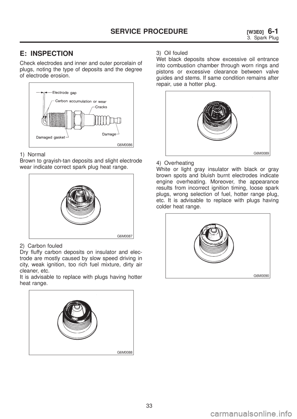
E: INSPECTION
Check electrodes and inner and outer porcelain of
plugs, noting the type of deposits and the degree
of electrode erosion.
G6M0086
1) Normal
Brown to grayish-tan deposits and slight electrode
wear indicate correct spark plug heat range.
G6M0087
2) Carbon fouled
Dry fluffy carbon deposits on insulator and elec-
trode are mostly caused by slow speed driving in
city, weak ignition, too rich fuel mixture, dirty air
cleaner, etc.
It is advisable to replace with plugs having hotter
heat range.
G6M0088
3) Oil fouled
Wet black deposits show excessive oil entrance
into combustion chamber through worn rings and
pistons or excessive clearance between valve
guides and stems. If same condition remains after
repair, use a hotter plug.
G6M0089
4) Overheating
White or light gray insulator with black or gray
brown spots and bluish burnt electrodes indicate
engine overheating. Moreover, the appearance
results from incorrect ignition timing, loose spark
plugs, wrong selection of fuel, hotter range plug,
etc. It is advisable to replace with plugs having
colder heat range.
G6M0090
33
[W3E0]6-1SERVICE PROCEDURE
3. Spark Plug
Page 1253 of 1456
13. Rear Window Defogger
A: REMOVAL AND INSTALLATION
1. DEFOGGER SWITCH
1) Remove screws which secure meter visor.
2) Remove meter visor from instrument panel
while disconnecting connectors.
3) Remove rear window defogger switch from
meter visor.
4) Installation is in the reverse order of removal.
B: INSPECTION
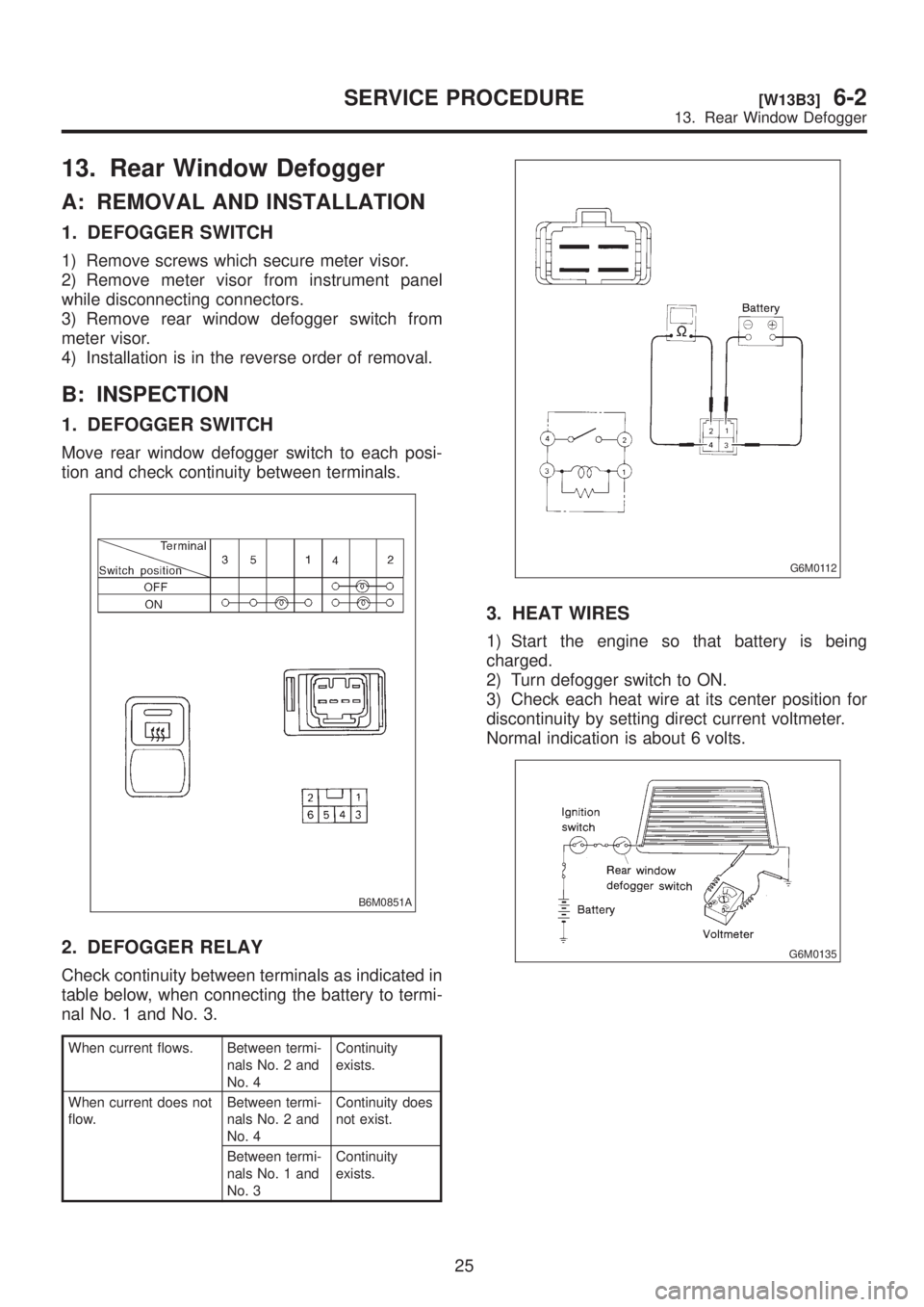
1. DEFOGGER SWITCH
Move rear window defogger switch to each posi-
tion and check continuity between terminals.
B6M0851A
2. DEFOGGER RELAY
Check continuity between terminals as indicated in
table below, when connecting the battery to termi-
nal No. 1 and No. 3.
When current flows. Between termi-
nals No. 2 and
No. 4Continuity
exists.
When current does not
flow.Between termi-
nals No. 2 and
No. 4Continuity does
not exist.
Between termi-
nals No. 1 and
No. 3Continuity
exists.
G6M0112
3. HEAT WIRES
1) Start the engine so that battery is being
charged.
2) Turn defogger switch to ON.
3) Check each heat wire at its center position for
discontinuity by setting direct current voltmeter.
Normal indication is about 6 volts.
G6M0135
25
[W13B3]6-2SERVICE PROCEDURE
13. Rear Window Defogger
Page 1254 of 1456
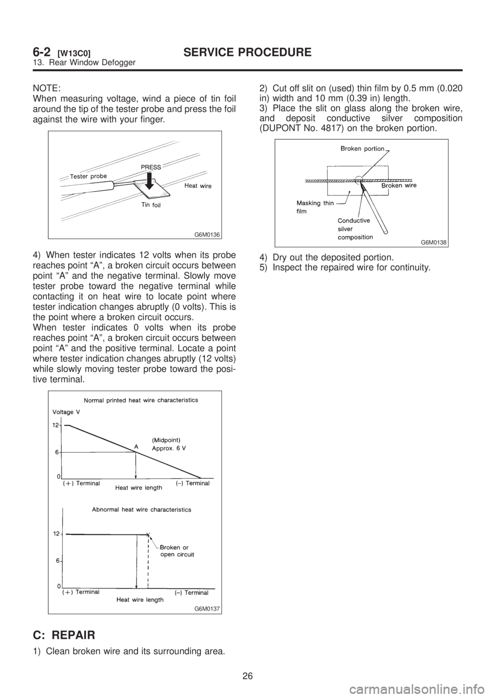
NOTE:
When measuring voltage, wind a piece of tin foil
around the tip of the tester probe and press the foil
against the wire with your finger.
G6M0136
4) When tester indicates 12 volts when its probe
reaches point ªAº, a broken circuit occurs between
point ªAº and the negative terminal. Slowly move
tester probe toward the negative terminal while
contacting it on heat wire to locate point where
tester indication changes abruptly (0 volts). This is
the point where a broken circuit occurs.
When tester indicates 0 volts when its probe
reaches point ªAº, a broken circuit occurs between
point ªAº and the positive terminal. Locate a point
where tester indication changes abruptly (12 volts)
while slowly moving tester probe toward the posi-
tive terminal.
G6M0137
C: REPAIR
1) Clean broken wire and its surrounding area.2) Cut off slit on (used) thin film by 0.5 mm (0.020
in) width and 10 mm (0.39 in) length.
3) Place the slit on glass along the broken wire,
and deposit conductive silver composition
(DUPONT No. 4817) on the broken portion.
G6M0138
4) Dry out the deposited portion.
5) Inspect the repaired wire for continuity.
26
6-2[W13C0]SERVICE PROCEDURE
13. Rear Window Defogger
Page 1265 of 1456
19. Remote Controlled
Rearview Mirror
A: REMOVAL AND INSTALLATION
1. REMOTE CONTROLLED REARVIEW
MIRROR SWITCH
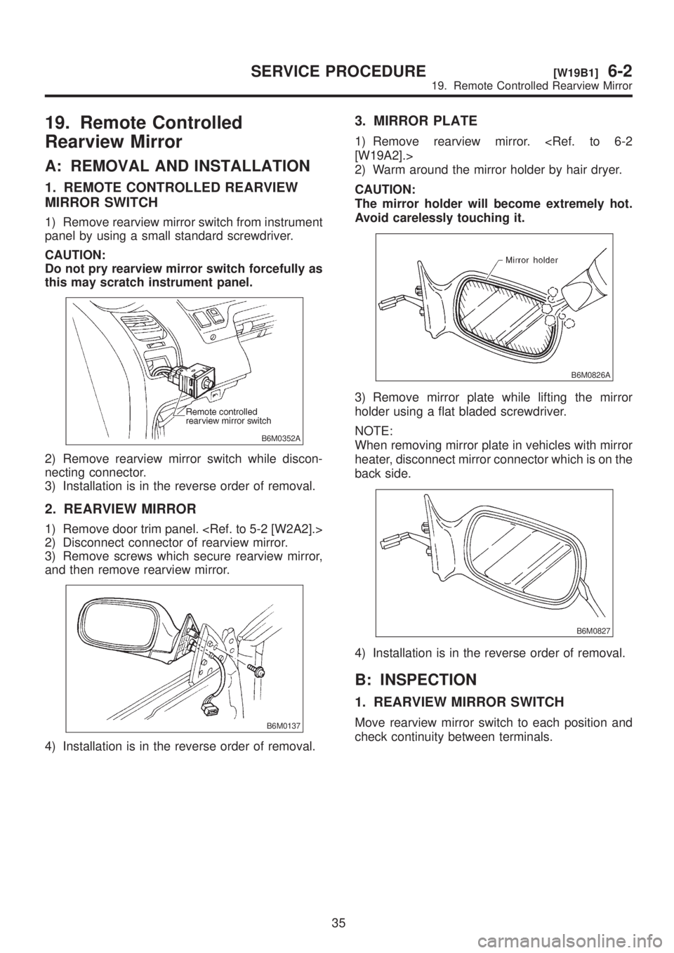
1) Remove rearview mirror switch from instrument
panel by using a small standard screwdriver.
CAUTION:
Do not pry rearview mirror switch forcefully as
this may scratch instrument panel.
B6M0352A
2) Remove rearview mirror switch while discon-
necting connector.
3) Installation is in the reverse order of removal.
2. REARVIEW MIRROR
1) Remove door trim panel.
2) Disconnect connector of rearview mirror.
3) Remove screws which secure rearview mirror,
and then remove rearview mirror.
B6M0137
4) Installation is in the reverse order of removal.
3. MIRROR PLATE
1) Remove rearview mirror.
[W19A2].>
2) Warm around the mirror holder by hair dryer.
CAUTION:
The mirror holder will become extremely hot.
Avoid carelessly touching it.
B6M0826A
3) Remove mirror plate while lifting the mirror
holder using a flat bladed screwdriver.
NOTE:
When removing mirror plate in vehicles with mirror
heater, disconnect mirror connector which is on the
back side.
B6M0827
4) Installation is in the reverse order of removal.
B: INSPECTION
1. REARVIEW MIRROR SWITCH
Move rearview mirror switch to each position and
check continuity between terminals.
35
[W19B1]6-2SERVICE PROCEDURE
19. Remote Controlled Rearview Mirror
Page 1276 of 1456
24. Seat Heater
A: REMOVAL AND INSTALLATION
1. SEAT HEATER
Remove and install front seat (including heater
system).
2. SEAT HEATER SWITCH
1) Remove screws which secure rear console
cover, and then remove rear console cover.
2) Remove seat heater switch from console cover.
B6M0150A
3) Installation is in the reverse order of removal.
B: INSPECTION
1. SEAT HEATER
Check continuity between terminals of seat heater
connector:
IBetween terminals No. 1 and No. 3
IBetween terminals No. 1 and No. 4
IBetween terminals No. 3 and No. 4
B6M0151A
2. SEAT HEATER SWITCH
Set switch to each position and check continuity
between terminals.
B6M0845A
45
[W24B2]6-2SERVICE PROCEDURE
24. Seat Heater
Page 1296 of 1456
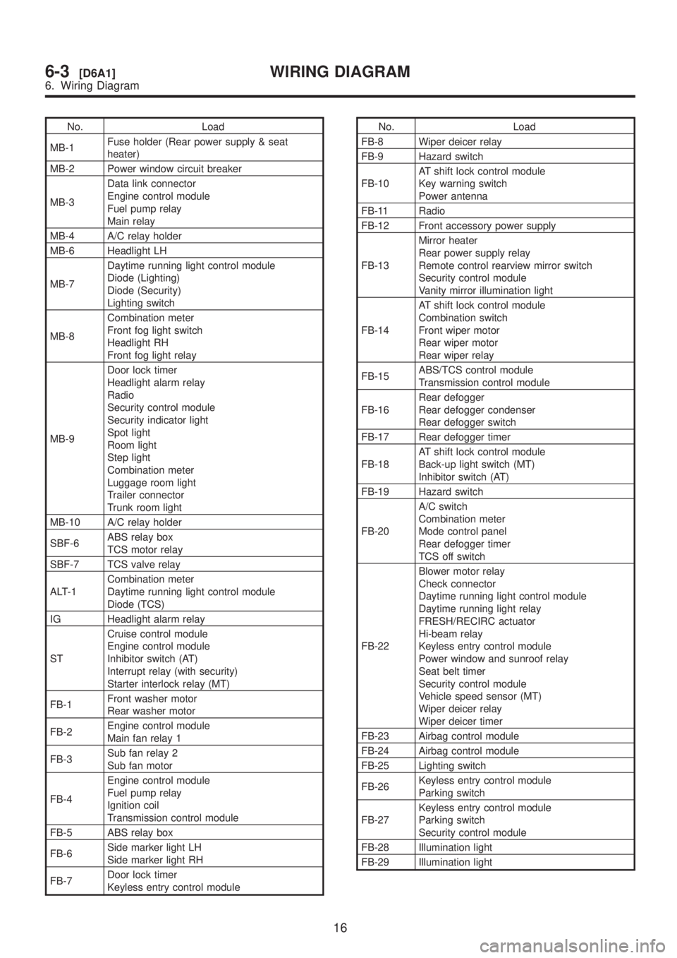
No. Load
MB-1Fuse holder (Rear power supply & seat
heater)
MB-2 Power window circuit breaker
MB-3Data link connector
Engine control module
Fuel pump relay
Main relay
MB-4 A/C relay holder
MB-6 Headlight LH
MB-7Daytime running light control module
Diode (Lighting)
Diode (Security)
Lighting switch
MB-8Combination meter
Front fog light switch
Headlight RH
Front fog light relay
MB-9Door lock timer
Headlight alarm relay
Radio
Security control module
Security indicator light
Spot light
Room light
Step light
Combination meter
Luggage room light
Trailer connector
Trunk room light
MB-10 A/C relay holder
SBF-6ABS relay box
TCS motor relay
SBF-7 TCS valve relay
ALT-1Combination meter
Daytime running light control module
Diode (TCS)
IG Headlight alarm relay
STCruise control module
Engine control module
Inhibitor switch (AT)
Interrupt relay (with security)
Starter interlock relay (MT)
FB-1Front washer motor
Rear washer motor
FB-2Engine control module
Main fan relay 1
FB-3Sub fan relay 2
Sub fan motor
FB-4Engine control module
Fuel pump relay
Ignition coil
Transmission control module
FB-5 ABS relay box
FB-6Side marker light LH
Side marker light RH
FB-7Door lock timer
Keyless entry control moduleNo. Load
FB-8 Wiper deicer relay
FB-9 Hazard switch
FB-10AT shift lock control module
Key warning switch
Power antenna
FB-11 Radio
FB-12 Front accessory power supply
FB-13Mirror heater
Rear power supply relay
Remote control rearview mirror switch
Security control module
Vanity mirror illumination light
FB-14AT shift lock control module
Combination switch
Front wiper motor
Rear wiper motor
Rear wiper relay
FB-15ABS/TCS control module
Transmission control module
FB-16Rear defogger
Rear defogger condenser
Rear defogger switch
FB-17 Rear defogger timer
FB-18AT shift lock control module
Back-up light switch (MT)
Inhibitor switch (AT)
FB-19 Hazard switch
FB-20A/C switch
Combination meter
Mode control panel
Rear defogger timer
TCS off switch
FB-22Blower motor relay
Check connector
Daytime running light control module
Daytime running light relay
FRESH/RECIRC actuator
Hi-beam relay
Keyless entry control module
Power window and sunroof relay
Seat belt timer
Security control module
Vehicle speed sensor (MT)
Wiper deicer relay
Wiper deicer timer
FB-23 Airbag control module
FB-24 Airbag control module
FB-25 Lighting switch
FB-26Keyless entry control module
Parking switch
FB-27Keyless entry control module
Parking switch
Security control module
FB-28 Illumination light
FB-29 Illumination light
16
6-3[D6A1]WIRING DIAGRAM
6. Wiring Diagram