1999 SUBARU LEGACY heat
[x] Cancel search: heatPage 982 of 1456
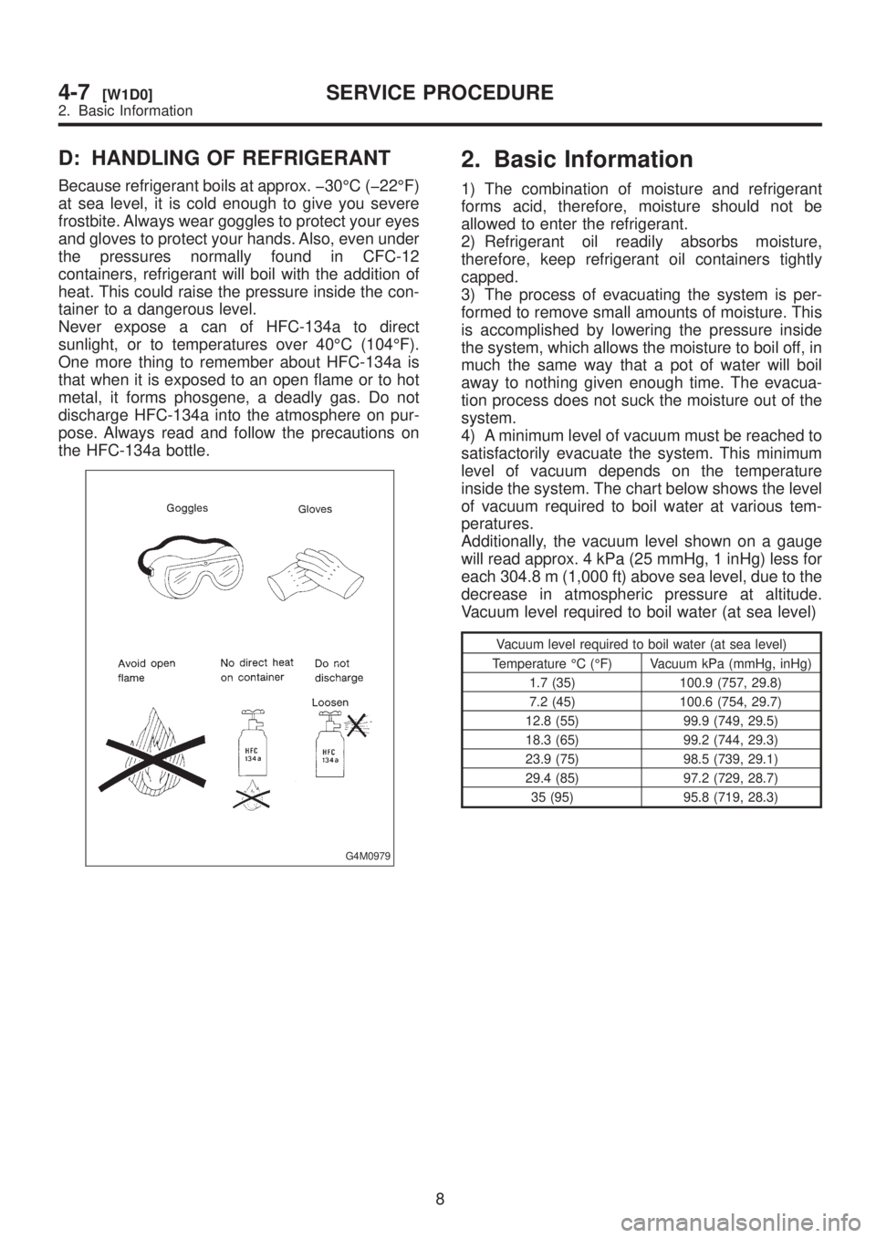
D: HANDLING OF REFRIGERANT
Because refrigerant boils at approx. þ30ÉC (þ22ÉF)
at sea level, it is cold enough to give you severe
frostbite. Always wear goggles to protect your eyes
and gloves to protect your hands. Also, even under
the pressures normally found in CFC-12
containers, refrigerant will boil with the addition of
heat. This could raise the pressure inside the con-
tainer to a dangerous level.
Never expose a can of HFC-134a to direct
sunlight, or to temperatures over 40ÉC (104ÉF).
One more thing to remember about HFC-134a is
that when it is exposed to an open flame or to hot
metal, it forms phosgene, a deadly gas. Do not
discharge HFC-134a into the atmosphere on pur-
pose. Always read and follow the precautions on
the HFC-134a bottle.
G4M0979
2. Basic Information
1) The combination of moisture and refrigerant
forms acid, therefore, moisture should not be
allowed to enter the refrigerant.
2) Refrigerant oil readily absorbs moisture,
therefore, keep refrigerant oil containers tightly
capped.
3) The process of evacuating the system is per-
formed to remove small amounts of moisture. This
is accomplished by lowering the pressure inside
the system, which allows the moisture to boil off, in
much the same way that a pot of water will boil
away to nothing given enough time. The evacua-
tion process does not suck the moisture out of the
system.
4) A minimum level of vacuum must be reached to
satisfactorily evacuate the system. This minimum
level of vacuum depends on the temperature
inside the system. The chart below shows the level
of vacuum required to boil water at various tem-
peratures.
Additionally, the vacuum level shown on a gauge
will read approx. 4 kPa (25 mmHg, 1 inHg) less for
each 304.8 m (1,000 ft) above sea level, due to the
decrease in atmospheric pressure at altitude.
Vacuum level required to boil water (at sea level)
Vacuum level required to boil water (at sea level)
Temperature ÉC (ÉF) Vacuum kPa (mmHg, inHg)
1.7 (35) 100.9 (757, 29.8)
7.2 (45) 100.6 (754, 29.7)
12.8 (55) 99.9 (749, 29.5)
18.3 (65) 99.2 (744, 29.3)
23.9 (75) 98.5 (739, 29.1)
29.4 (85) 97.2 (729, 28.7)
35 (95) 95.8 (719, 28.3)
8
4-7[W1D0]SERVICE PROCEDURE
2. Basic Information
Page 983 of 1456
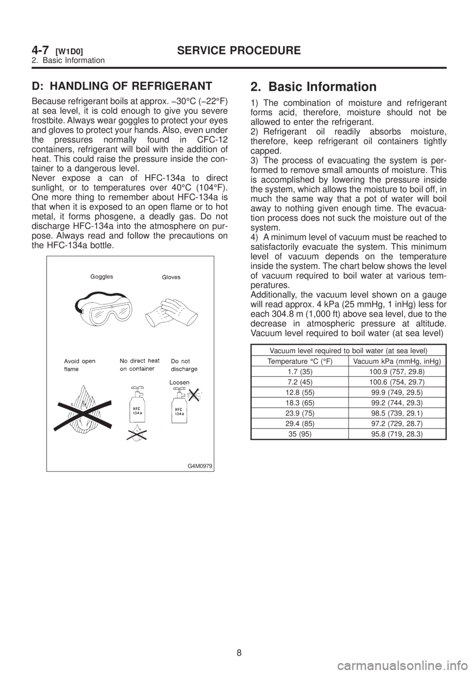
D: HANDLING OF REFRIGERANT
Because refrigerant boils at approx. þ30ÉC (þ22ÉF)
at sea level, it is cold enough to give you severe
frostbite. Always wear goggles to protect your eyes
and gloves to protect your hands. Also, even under
the pressures normally found in CFC-12
containers, refrigerant will boil with the addition of
heat. This could raise the pressure inside the con-
tainer to a dangerous level.
Never expose a can of HFC-134a to direct
sunlight, or to temperatures over 40ÉC (104ÉF).
One more thing to remember about HFC-134a is
that when it is exposed to an open flame or to hot
metal, it forms phosgene, a deadly gas. Do not
discharge HFC-134a into the atmosphere on pur-
pose. Always read and follow the precautions on
the HFC-134a bottle.
G4M0979
2. Basic Information
1) The combination of moisture and refrigerant
forms acid, therefore, moisture should not be
allowed to enter the refrigerant.
2) Refrigerant oil readily absorbs moisture,
therefore, keep refrigerant oil containers tightly
capped.
3) The process of evacuating the system is per-
formed to remove small amounts of moisture. This
is accomplished by lowering the pressure inside
the system, which allows the moisture to boil off, in
much the same way that a pot of water will boil
away to nothing given enough time. The evacua-
tion process does not suck the moisture out of the
system.
4) A minimum level of vacuum must be reached to
satisfactorily evacuate the system. This minimum
level of vacuum depends on the temperature
inside the system. The chart below shows the level
of vacuum required to boil water at various tem-
peratures.
Additionally, the vacuum level shown on a gauge
will read approx. 4 kPa (25 mmHg, 1 inHg) less for
each 304.8 m (1,000 ft) above sea level, due to the
decrease in atmospheric pressure at altitude.
Vacuum level required to boil water (at sea level)
Vacuum level required to boil water (at sea level)
Temperature ÉC (ÉF) Vacuum kPa (mmHg, inHg)
1.7 (35) 100.9 (757, 29.8)
7.2 (45) 100.6 (754, 29.7)
12.8 (55) 99.9 (749, 29.5)
18.3 (65) 99.2 (744, 29.3)
23.9 (75) 98.5 (739, 29.1)
29.4 (85) 97.2 (729, 28.7)
35 (95) 95.8 (719, 28.3)
8
4-7[W1D0]SERVICE PROCEDURE
2. Basic Information
Page 1017 of 1456
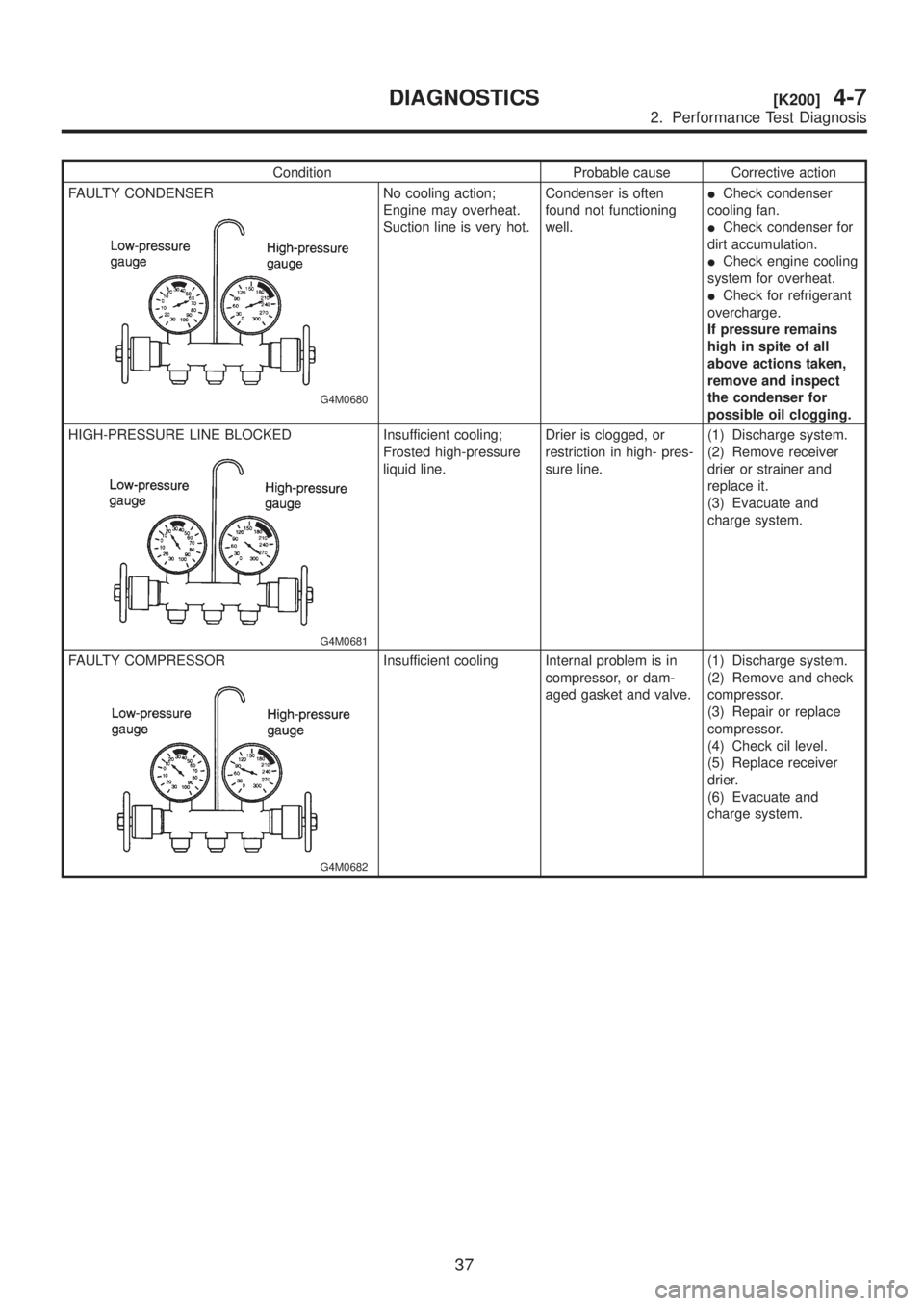
Condition Probable cause Corrective action
FAULTY CONDENSER
G4M0680
No cooling action;
Engine may overheat.
Suction line is very hot.Condenser is often
found not functioning
well.ICheck condenser
cooling fan.
ICheck condenser for
dirt accumulation.
ICheck engine cooling
system for overheat.
ICheck for refrigerant
overcharge.
If pressure remains
high in spite of all
above actions taken,
remove and inspect
the condenser for
possible oil clogging.
HIGH-PRESSURE LINE BLOCKED
G4M0681
Insufficient cooling;
Frosted high-pressure
liquid line.Drier is clogged, or
restriction in high- pres-
sure line.(1) Discharge system.
(2) Remove receiver
drier or strainer and
replace it.
(3) Evacuate and
charge system.
FAULTY COMPRESSOR
G4M0682
Insufficient cooling Internal problem is in
compressor, or dam-
aged gasket and valve.(1) Discharge system.
(2) Remove and check
compressor.
(3) Repair or replace
compressor.
(4) Check oil level.
(5) Replace receiver
drier.
(6) Evacuate and
charge system.
37
[K200]4-7DIAGNOSTICS
2. Performance Test Diagnosis
Page 1073 of 1456
Process
No.Process name Job contents
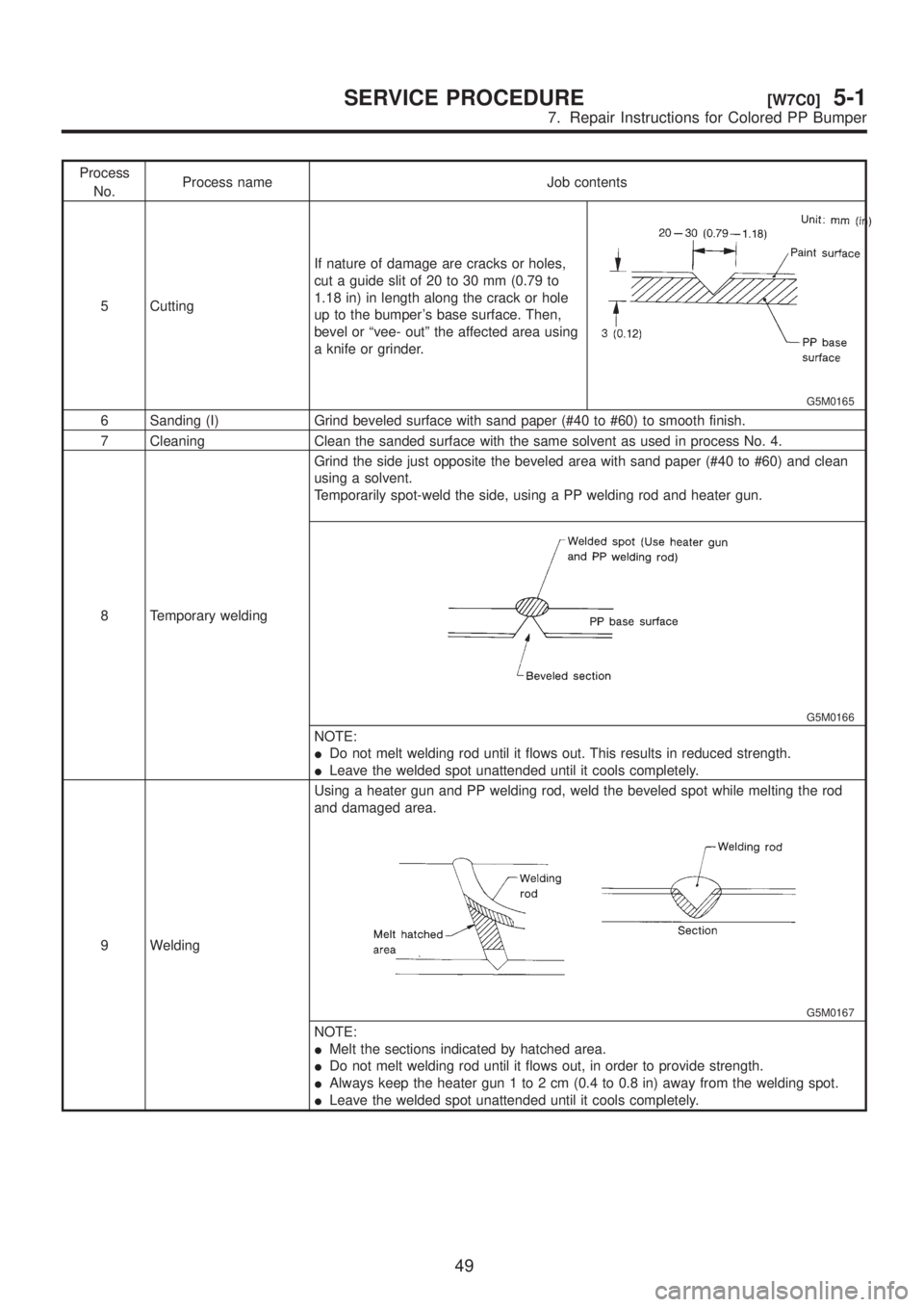
5 CuttingIf nature of damage are cracks or holes,
cut a guide slit of 20 to 30 mm (0.79 to
1.18 in) in length along the crack or hole
up to the bumper's base surface. Then,
bevel or ªvee- outº the affected area using
a knife or grinder.
G5M0165
6 Sanding (I) Grind beveled surface with sand paper (#40 to #60) to smooth finish.
7 Cleaning Clean the sanded surface with the same solvent as used in process No. 4.
8 Temporary weldingGrind the side just opposite the beveled area with sand paper (#40 to #60) and clean
using a solvent.
Temporarily spot-weld the side, using a PP welding rod and heater gun.
G5M0166
NOTE:
IDo not melt welding rod until it flows out. This results in reduced strength.
ILeave the welded spot unattended until it cools completely.
9 WeldingUsing a heater gun and PP welding rod, weld the beveled spot while melting the rod
and damaged area.
G5M0167
NOTE:
IMelt the sections indicated by hatched area.
IDo not melt welding rod until it flows out, in order to provide strength.
IAlways keep the heater gun 1 to 2 cm (0.4 to 0.8 in) away from the welding spot.
ILeave the welded spot unattended until it cools completely.
49
[W7C0]5-1SERVICE PROCEDURE
7. Repair Instructions for Colored PP Bumper
Page 1074 of 1456
Process
No.Process name Job contents
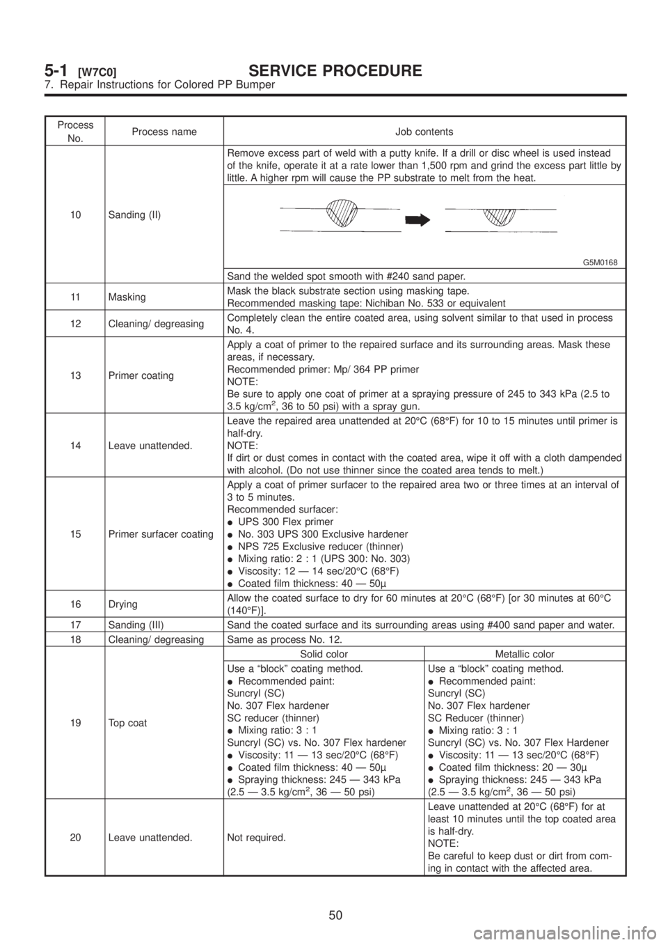
10 Sanding (II)Remove excess part of weld with a putty knife. If a drill or disc wheel is used instead
of the knife, operate it at a rate lower than 1,500 rpm and grind the excess part little by
little. A higher rpm will cause the PP substrate to melt from the heat.
G5M0168
Sand the welded spot smooth with #240 sand paper.
11 MaskingMask the black substrate section using masking tape.
Recommended masking tape: Nichiban No. 533 or equivalent
12 Cleaning/ degreasingCompletely clean the entire coated area, using solvent similar to that used in process
No. 4.
13 Primer coatingApply a coat of primer to the repaired surface and its surrounding areas. Mask these
areas, if necessary.
Recommended primer: Mp/ 364 PP primer
NOTE:
Be sure to apply one coat of primer at a spraying pressure of 245 to 343 kPa (2.5 to
3.5 kg/cm
2, 36 to 50 psi) with a spray gun.
14 Leave unattended.Leave the repaired area unattended at 20ÉC (68ÉF) for 10 to 15 minutes until primer is
half-dry.
NOTE:
If dirt or dust comes in contact with the coated area, wipe it off with a cloth dampended
with alcohol. (Do not use thinner since the coated area tends to melt.)
15 Primer surfacer coatingApply a coat of primer surfacer to the repaired area two or three times at an interval of
3 to 5 minutes.
Recommended surfacer:
IUPS 300 Flex primer
INo. 303 UPS 300 Exclusive hardener
INPS 725 Exclusive reducer (thinner)
IMixing ratio:2:1(UPS 300: No. 303)
IViscosity: 12 Ð 14 sec/20ÉC (68ÉF)
ICoated film thickness: 40 Ð 50
16 DryingAllow the coated surface to dry for 60 minutes at 20ÉC (68ÉF) [or 30 minutes at 60ÉC
(140ÉF)].
17 Sanding (III) Sand the coated surface and its surrounding areas using #400 sand paper and water.
18 Cleaning/ degreasing Same as process No. 12.
19 Top coatSolid color Metallic color
Use a ªblockº coating method.
IRecommended paint:
Suncryl (SC)
No. 307 Flex hardener
SC reducer (thinner)
IMixing ratio:3:1
Suncryl (SC) vs. No. 307 Flex hardener
IViscosity: 11 Ð 13 sec/20ÉC (68ÉF)
ICoated film thickness: 40 Ð 50
ISpraying thickness: 245 Ð 343 kPa
(2.5 Ð 3.5 kg/cm
2, 36 Ð 50 psi)Use a ªblockº coating method.
IRecommended paint:
Suncryl (SC)
No. 307 Flex hardener
SC Reducer (thinner)
IMixing ratio:3:1
Suncryl (SC) vs. No. 307 Flex Hardener
IViscosity: 11 Ð 13 sec/20ÉC (68ÉF)
ICoated film thickness: 20 Ð 30
ISpraying thickness: 245 Ð 343 kPa
(2.5 Ð 3.5 kg/cm2, 36 Ð 50 psi)
20 Leave unattended. Not required.Leave unattended at 20ÉC (68ÉF) for at
least 10 minutes until the top coated area
is half-dry.
NOTE:
Be careful to keep dust or dirt from com-
ing in contact with the affected area.
50
5-1[W7C0]SERVICE PROCEDURE
7. Repair Instructions for Colored PP Bumper
Page 1157 of 1456
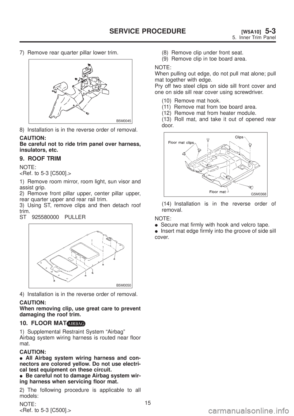
7) Remove rear quarter pillar lower trim.
B5M0045
8) Installation is in the reverse order of removal.
CAUTION:
Be careful not to ride trim panel over harness,
insulators, etc.
9. ROOF TRIM
NOTE:
1) Remove room mirror, room light, sun visor and
assist grip.
2) Remove front pillar upper, center pillar upper,
rear quarter upper and rear rail trim.
3) Using ST, remove clips and then detach roof
trim.
ST 925580000 PULLER
B5M0050
4) Installation is in the reverse order of removal.
CAUTION:
When removing clip, use great care to prevent
damaging the roof trim.
10. FLOOR MAT
1) Supplemental Restraint System ªAirbagº
Airbag system wiring harness is routed near floor
mat.
CAUTION:
IAll Airbag system wiring harness and con-
nectors are colored yellow. Do not use electri-
cal test equipment on these circuit.
IBe careful not to damage Airbag system wir-
ing harness when servicing floor mat.
2) The following procedure is applicable to all
models:
NOTE:
(9) Remove clip in toe board area.
NOTE:
When pulling out edge, do not pull mat alone; pull
mat together with edge.
Pry off two steel clips on side sill front cover and
one on side sill rear cover using screwdriver.
(10) Remove mat hook.
(11) Remove mat from toe board area.
(12) Remove mat from heater module.
(13) Roll mat, and take it out of opened rear
door.
G5M0368
(14) Installation is in the reverse order of
removal.
NOTE:
ISecure mat firmly with hook and velcro tape.
IInsert mat edge firmly into the groove of side sill
cover.
15
[W5A10]5-3SERVICE PROCEDURE
5. Inner Trim Panel
Page 1161 of 1456
1. Instrument Panel
A: REMOVAL
Airbag system wiring harness is routed near com-
bination meter.
CAUTION:
IAll Airbag system wiring harness and con-
nectors are colored yellow. Do not use electri-
cal test equipment on these circuits.
IBe careful not to damage Airbag system wir-
ing harness when servicing the combination
meter.
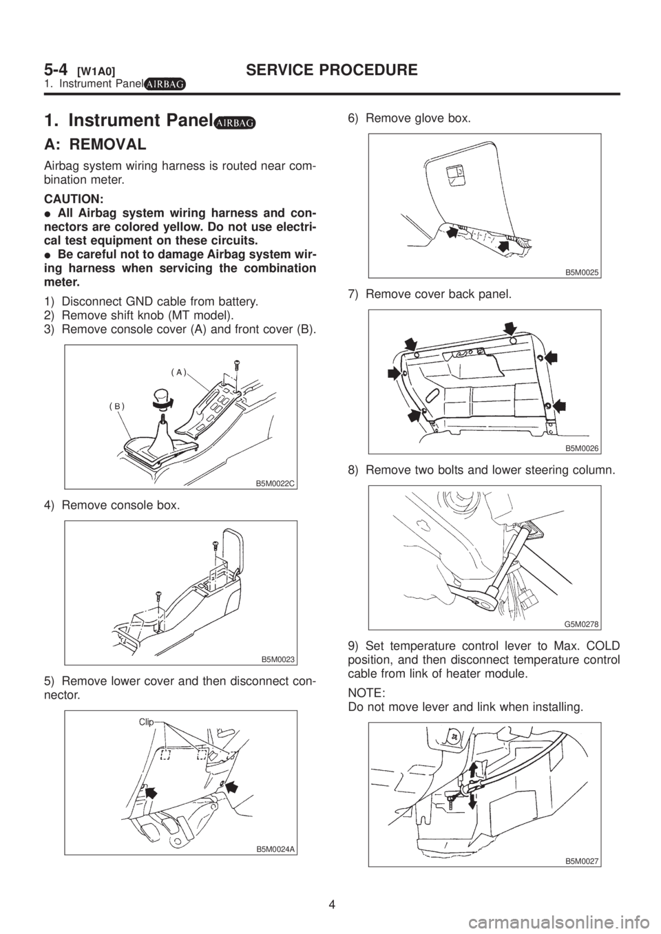
1) Disconnect GND cable from battery.
2) Remove shift knob (MT model).
3) Remove console cover (A) and front cover (B).
B5M0022C
4) Remove console box.
B5M0023
5) Remove lower cover and then disconnect con-
nector.
B5M0024A
6) Remove glove box.
B5M0025
7) Remove cover back panel.
B5M0026
8) Remove two bolts and lower steering column.
G5M0278
9) Set temperature control lever to Max. COLD
position, and then disconnect temperature control
cable from link of heater module.
NOTE:
Do not move lever and link when installing.
B5M0027
4
5-4[W1A0]SERVICE PROCEDURE
1. Instrument Panel
Page 1171 of 1456
3. Airbag Module
A: REMOVAL AND INSTALLATION
CAUTION:
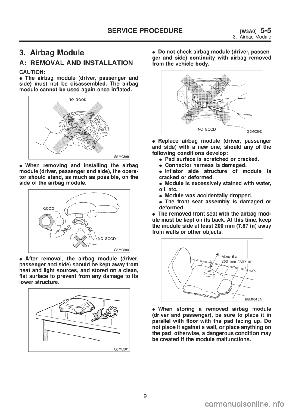
IThe airbag module (driver, passenger and
side) must not be disassembled. The airbag
module cannot be used again once inflated.
G5M0299
IWhen removing and installing the airbag
module (driver, passenger and side), the opera-
tor should stand, as much as possible, on the
side of the airbag module.
G5M0300
IAfter removal, the airbag module (driver,
passenger and side) should be kept away from
heat and light sources, and stored on a clean,
flat surface to prevent from any damage to its
lower structure.
G5M0301
IDo not check airbag module (driver, passen-
ger and side) continuity with airbag removed
from the vehicle body.
G5M0302
IReplace airbag module (driver, passenger
and side) with a new one, should any of the
following conditions develop:
IPad surface is scratched or cracked.
IConnector harness is damaged.
IInflator side structure of module is
cracked or deformed.
IModule is excessively stained with water,
oil, etc.
IModule was accidentally dropped.
IThe front seat assembly is damaged or
deformed.
IThe removed front seat with the airbag mod-
ule must be kept on its back. At this time, keep
the module side at least 200 mm (7.87 in) away
from walls or other objects.
B5M0515A
IWhen storing a removed airbag module
(driver and passenger), be sure to place it in
parallel with floor with the pad facing up. Do
not place it against a wall, or place anything on
the pad; otherwise, a dangerous condition may
be created if the module malfunctions.
9
[W3A0]5-5SERVICE PROCEDURE
3. Airbag Module