1999 SUBARU LEGACY rear
[x] Cancel search: rearPage 908 of 1456
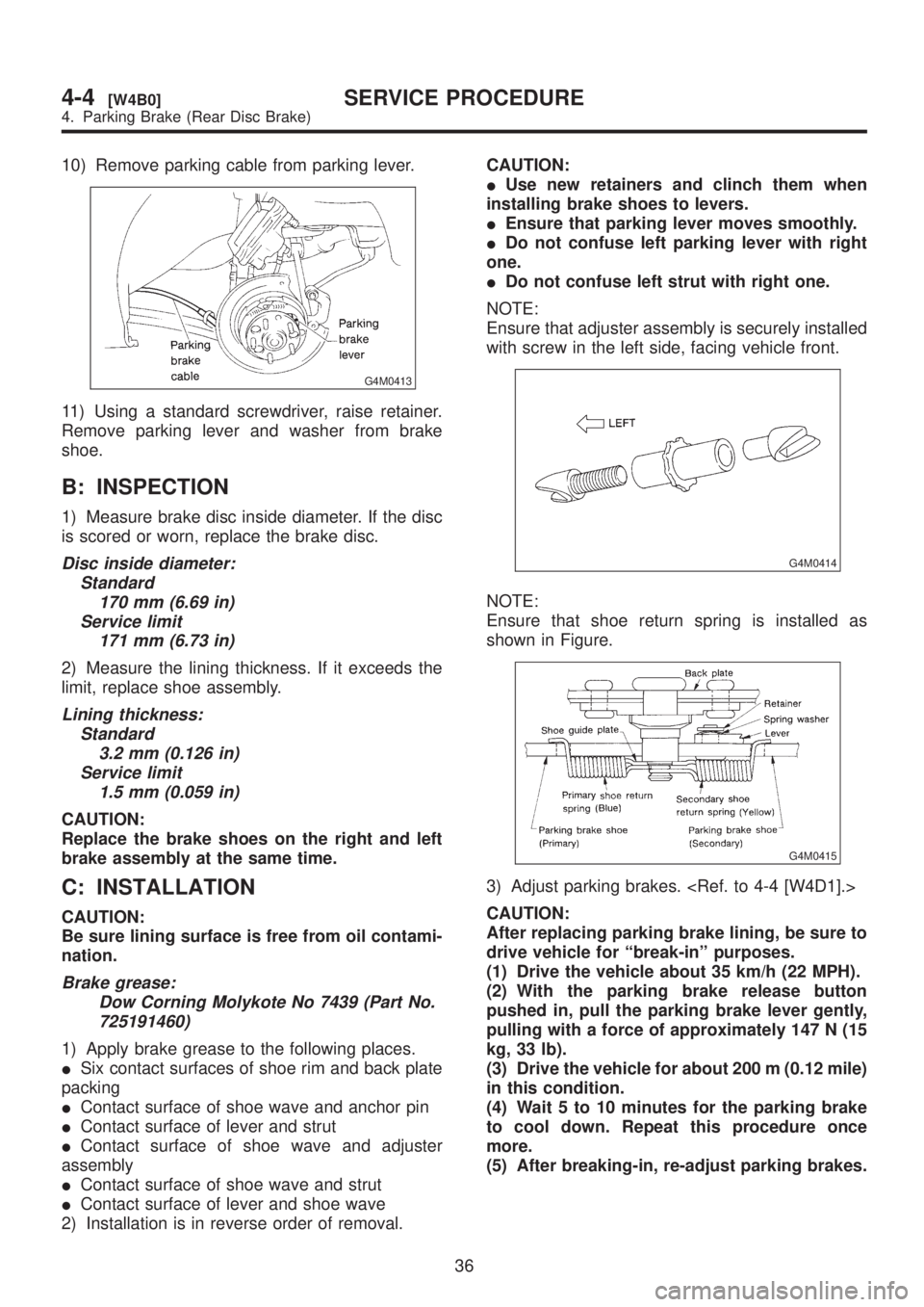
10) Remove parking cable from parking lever.
G4M0413
11) Using a standard screwdriver, raise retainer.
Remove parking lever and washer from brake
shoe.
B: INSPECTION
1) Measure brake disc inside diameter. If the disc
is scored or worn, replace the brake disc.
Disc inside diameter:
Standard
170 mm (6.69 in)
Service limit
171 mm (6.73 in)
2) Measure the lining thickness. If it exceeds the
limit, replace shoe assembly.
Lining thickness:
Standard
3.2 mm (0.126 in)
Service limit
1.5 mm (0.059 in)
CAUTION:
Replace the brake shoes on the right and left
brake assembly at the same time.
C: INSTALLATION
CAUTION:
Be sure lining surface is free from oil contami-
nation.
Brake grease:
Dow Corning Molykote No 7439 (Part No.
725191460)
1) Apply brake grease to the following places.
ISix contact surfaces of shoe rim and back plate
packing
IContact surface of shoe wave and anchor pin
IContact surface of lever and strut
IContact surface of shoe wave and adjuster
assembly
IContact surface of shoe wave and strut
IContact surface of lever and shoe wave
2) Installation is in reverse order of removal.CAUTION:
IUse new retainers and clinch them when
installing brake shoes to levers.
IEnsure that parking lever moves smoothly.
IDo not confuse left parking lever with right
one.
IDo not confuse left strut with right one.
NOTE:
Ensure that adjuster assembly is securely installed
with screw in the left side, facing vehicle front.
G4M0414
NOTE:
Ensure that shoe return spring is installed as
shown in Figure.
G4M0415
3) Adjust parking brakes.
CAUTION:
After replacing parking brake lining, be sure to
drive vehicle for ªbreak-inº purposes.
(1) Drive the vehicle about 35 km/h (22 MPH).
(2) With the parking brake release button
pushed in, pull the parking brake lever gently,
pulling with a force of approximately 147 N (15
kg, 33 lb).
(3) Drive the vehicle for about 200 m (0.12 mile)
in this condition.
(4) Wait 5 to 10 minutes for the parking brake
to cool down. Repeat this procedure once
more.
(5) After breaking-in, re-adjust parking brakes.
36
4-4[W4B0]SERVICE PROCEDURE
4. Parking Brake (Rear Disc Brake)
Page 918 of 1456
7) While holding hexagonal part of brake hose fit-
ting with a wrench, tighten flare nut to the specified
torque.
Tightening torque (Brake pipe flare nut):
15+3/þ2N´m (1.5+0.3/þ0.2kg-m, 10.8+2.2/þ1.4ft-lb)
8) Bleed air from the brake system.
2. REAR BRAKE HOSE
1) Pass brake hose through the hole of bracket,
and lightly tighten flare nut to connect brake pipe.
2) Insert clamp upward to fix brake hose.
3) While holding hexagonal part of brake hose fit-
ting with a wrench, tighten flare nut to the specified
torque.
Tightening torque (Brake pipe flare nut):
15+3/þ2N´m (1.5+0.3/þ0.2kg-m, 10.8+2.2/þ1.4ft-lb)
4) Bleed air from the brake system.
8. Hill Holder
A: REMOVAL
1) Drain brake fluid from reservoir of master cylin-
der.
2) Remove adjusting nut and cable clamp, and
disconnect PHV cable from cable bracket on
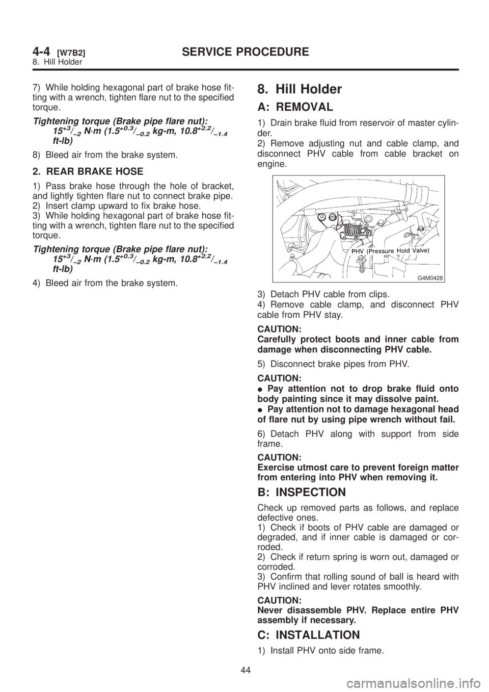
engine.
G4M0428
3) Detach PHV cable from clips.
4) Remove cable clamp, and disconnect PHV
cable from PHV stay.
CAUTION:
Carefully protect boots and inner cable from
damage when disconnecting PHV cable.
5) Disconnect brake pipes from PHV.
CAUTION:
IPay attention not to drop brake fluid onto
body painting since it may dissolve paint.
IPay attention not to damage hexagonal head
of flare nut by using pipe wrench without fail.
6) Detach PHV along with support from side
frame.
CAUTION:
Exercise utmost care to prevent foreign matter
from entering into PHV when removing it.
B: INSPECTION
Check up removed parts as follows, and replace
defective ones.
1) Check if boots of PHV cable are damaged or
degraded, and if inner cable is damaged or cor-
roded.
2) Check if return spring is worn out, damaged or
corroded.
3) Confirm that rolling sound of ball is heard with
PHV inclined and lever rotates smoothly.
CAUTION:
Never disassemble PHV. Replace entire PHV
assembly if necessary.
C: INSTALLATION
1) Install PHV onto side frame.
44
4-4[W7B2]SERVICE PROCEDURE
8. Hill Holder
Page 919 of 1456
7) While holding hexagonal part of brake hose fit-
ting with a wrench, tighten flare nut to the specified
torque.
Tightening torque (Brake pipe flare nut):
15+3/þ2N´m (1.5+0.3/þ0.2kg-m, 10.8+2.2/þ1.4ft-lb)
8) Bleed air from the brake system.
2. REAR BRAKE HOSE
1) Pass brake hose through the hole of bracket,
and lightly tighten flare nut to connect brake pipe.
2) Insert clamp upward to fix brake hose.
3) While holding hexagonal part of brake hose fit-
ting with a wrench, tighten flare nut to the specified
torque.
Tightening torque (Brake pipe flare nut):
15+3/þ2N´m (1.5+0.3/þ0.2kg-m, 10.8+2.2/þ1.4ft-lb)
4) Bleed air from the brake system.
8. Hill Holder
A: REMOVAL
1) Drain brake fluid from reservoir of master cylin-
der.
2) Remove adjusting nut and cable clamp, and
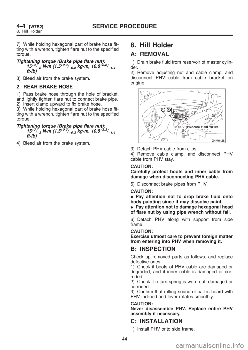
disconnect PHV cable from cable bracket on
engine.
G4M0428
3) Detach PHV cable from clips.
4) Remove cable clamp, and disconnect PHV
cable from PHV stay.
CAUTION:
Carefully protect boots and inner cable from
damage when disconnecting PHV cable.
5) Disconnect brake pipes from PHV.
CAUTION:
IPay attention not to drop brake fluid onto
body painting since it may dissolve paint.
IPay attention not to damage hexagonal head
of flare nut by using pipe wrench without fail.
6) Detach PHV along with support from side
frame.
CAUTION:
Exercise utmost care to prevent foreign matter
from entering into PHV when removing it.
B: INSPECTION
Check up removed parts as follows, and replace
defective ones.
1) Check if boots of PHV cable are damaged or
degraded, and if inner cable is damaged or cor-
roded.
2) Check if return spring is worn out, damaged or
corroded.
3) Confirm that rolling sound of ball is heard with
PHV inclined and lever rotates smoothly.
CAUTION:
Never disassemble PHV. Replace entire PHV
assembly if necessary.
C: INSTALLATION
1) Install PHV onto side frame.
44
4-4[W7B2]SERVICE PROCEDURE
8. Hill Holder
Page 921 of 1456
9. Parking Brake Lever
A: REPLACEMENT
1) Remove console box from front floor.
2) Disconnect electric connector for parking brake
switch.
3) Loosen parking brake adjuster, and remove
inner cable end from equalizer.
4) Remove parking brake lever.
5) Install parking brake lever in the reverse order
of removal.
Tightening torque (Lever installing bolt and
nut):
18
±5 N´m (1.8±0.5 kg-m, 13.0±3.6 ft-lb)
6) Adjust parking brake lever by turning adjusting
nut until parking brake lever stroke is set at 7 to 8
notches with operating force of 196 N (20 kg, 44
lb).
7) Tighten lock nut.
Tightening torque (Lock nut):
5.9
±1.5 N´m (0.60±0.15 kg-m, 4.3±1.1 ft-lb)
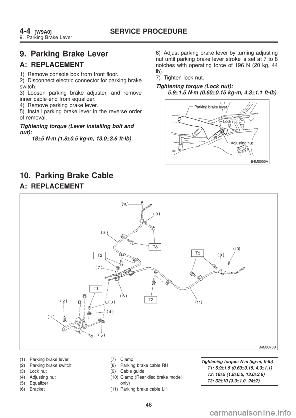
B4M0050A
10. Parking Brake Cable
A: REPLACEMENT
B4M0070B
(1) Parking brake lever
(2) Parking brake switch
(3) Lock nut
(4) Adjusting nut
(5) Equalizer
(6) Bracket(7) Clamp
(8) Parking brake cable RH
(9) Cable guide
(10) Clamp (Rear disc brake model
only)
(11) Parking brake cable LHTightening torque: N´m (kg-m, ft-lb)
T1:
5.9±1.5 (0.60±0.15, 4.3±1.1)
T2:18±5 (1.8±0.5, 13.0±3.6)
T3:32±10 (3.3±1.0, 24±7)
46
4-4[W9A0]SERVICE PROCEDURE
9. Parking Brake Lever
Page 922 of 1456
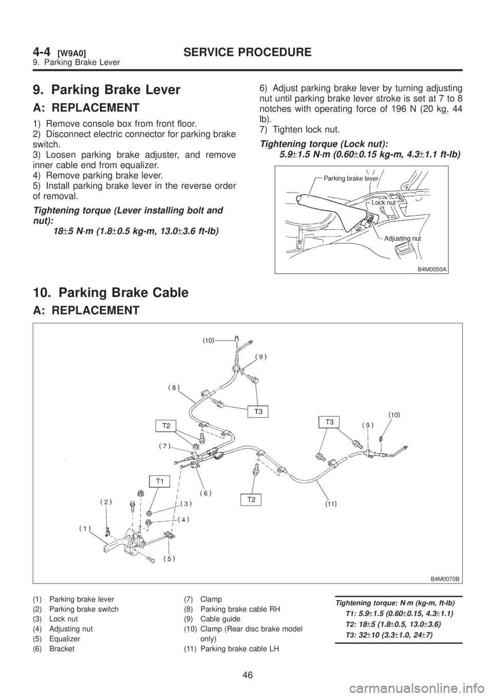
9. Parking Brake Lever
A: REPLACEMENT
1) Remove console box from front floor.
2) Disconnect electric connector for parking brake
switch.
3) Loosen parking brake adjuster, and remove
inner cable end from equalizer.
4) Remove parking brake lever.
5) Install parking brake lever in the reverse order
of removal.
Tightening torque (Lever installing bolt and
nut):
18
±5 N´m (1.8±0.5 kg-m, 13.0±3.6 ft-lb)
6) Adjust parking brake lever by turning adjusting
nut until parking brake lever stroke is set at 7 to 8
notches with operating force of 196 N (20 kg, 44
lb).
7) Tighten lock nut.
Tightening torque (Lock nut):
5.9
±1.5 N´m (0.60±0.15 kg-m, 4.3±1.1 ft-lb)
B4M0050A
10. Parking Brake Cable
A: REPLACEMENT
B4M0070B
(1) Parking brake lever
(2) Parking brake switch
(3) Lock nut
(4) Adjusting nut
(5) Equalizer
(6) Bracket(7) Clamp
(8) Parking brake cable RH
(9) Cable guide
(10) Clamp (Rear disc brake model
only)
(11) Parking brake cable LHTightening torque: N´m (kg-m, ft-lb)
T1:
5.9±1.5 (0.60±0.15, 4.3±1.1)
T2:18±5 (1.8±0.5, 13.0±3.6)
T3:32±10 (3.3±1.0, 24±7)
46
4-4[W9A0]SERVICE PROCEDURE
9. Parking Brake Lever
Page 923 of 1456
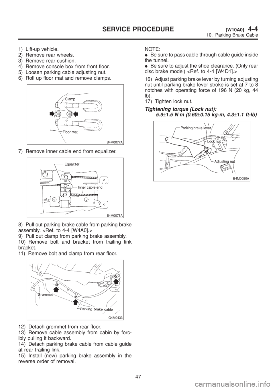
1) Lift-up vehicle.
2) Remove rear wheels.
3) Remove rear cushion.
4) Remove console box from front floor.
5) Loosen parking cable adjusting nut.
6) Roll up floor mat and remove clamps.
B4M0077A
7) Remove inner cable end from equalizer.
B4M0078A
8) Pull out parking brake cable from parking brake
assembly.
9) Pull out clamp from parking brake assembly.
10) Remove bolt and bracket from trailing link
bracket.
11) Remove bolt and clamp from rear floor.
G4M0433
12) Detach grommet from rear floor.
13) Remove cable assembly from cabin by forc-
ibly pulling it backward.
14) Detach parking brake cable from cable guide
at rear trailing link.
15) Install (new) parking brake assembly in the
reverse order of removal.NOTE:
IBe sure to pass cable through cable guide inside
the tunnel.
IBe sure to adjust the shoe clearance. (Only rear
disc brake model)
16) Adjust parking brake lever by turning adjusting
nut until parking brake lever stroke is set at 7 to 8
notches with operating force of 196 N (20 kg, 44
lb).
17) Tighten lock nut.
Tightening torque (Lock nut):
5.9
±1.5 N´m (0.60±0.15 kg-m, 4.3±1.1 ft-lb)
B4M0050A
47
[W10A0]4-4SERVICE PROCEDURE
10. Parking Brake Cable
Page 925 of 1456
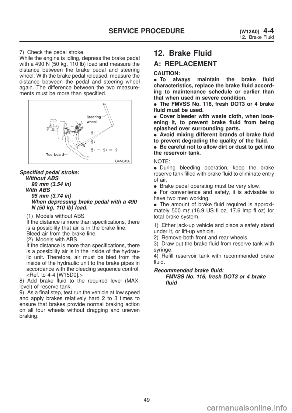
7) Check the pedal stroke.
While the engine is idling, depress the brake pedal
with a 490 N (50 kg, 110 lb) load and measure the
distance between the brake pedal and steering
wheel. With the brake pedal released, measure the
distance between the pedal and steering wheel
again. The difference between the two measure-
ments must be more than specified.
G4M0436
Specified pedal stroke:
Without ABS
90 mm (3.54 in)
With ABS
95 mm (3.74 in)
When depressing brake pedal with a 490
N (50 kg, 110 lb) load.
(1) Models without ABS
If the distance is more than specifications, there
is a possibility that air is in the brake line.
Bleed air from the brake line.
(2) Models with ABS
If the distance is more than specifications, there
is a possibility air is in the inside of the hydrau-
lic unit. Therefore, air must be bled from the
inside of the hydraulic unit to the brake pipes in
accordance with the bleeding sequence control.
8) Add brake fluid to the required level (MAX.
level) of reserve tank.
9) As a final step, test run the vehicle at low speed
and apply brakes relatively hard 2 to 3 times to
ensure that brakes provide normal braking action
on all four wheels without dragging and uneven
braking.
12. Brake Fluid
A: REPLACEMENT
CAUTION:
ITo always maintain the brake fluid
characteristics, replace the brake fluid accord-
ing to maintenance schedule or earlier than
that when used in severe condition.
IThe FMVSS No. 116, fresh DOT3 or 4 brake
fluid must be used.
ICover bleeder with waste cloth, when loos-
ening it, to prevent brake fluid from being
splashed over surrounding parts.
IAvoid mixing different brands of brake fluid
to prevent degrading the quality of the fluid.
IBe careful not to allow dirt or dust to get into
the reservoir tank.
NOTE:
IDuring bleeding operation, keep the brake
reserve tank filled with brake fluid to eliminate entry
of air.
IBrake pedal operating must be very slow.
IFor convenience and safety, it is advisable to
have two men working.
IThe amount of brake fluid required is approxi-
mately 500 m(16.9 US fl oz, 17.6 Imp fl oz) for
total brake system.
1) Either jack-up vehicle and place a safety stand
under it, or lift-up vehicle.
2) Remove both front and rear wheels.
3) Draw out the brake fluid from reserve tank with
syringe.
4) Refill reservoir tank with recommended brake
fluid.
Recommended brake fluid:
FMVSS No. 116, fresh DOT3 or 4 brake
fluid
49
[W12A0]4-4SERVICE PROCEDURE
12. Brake Fluid
Page 926 of 1456
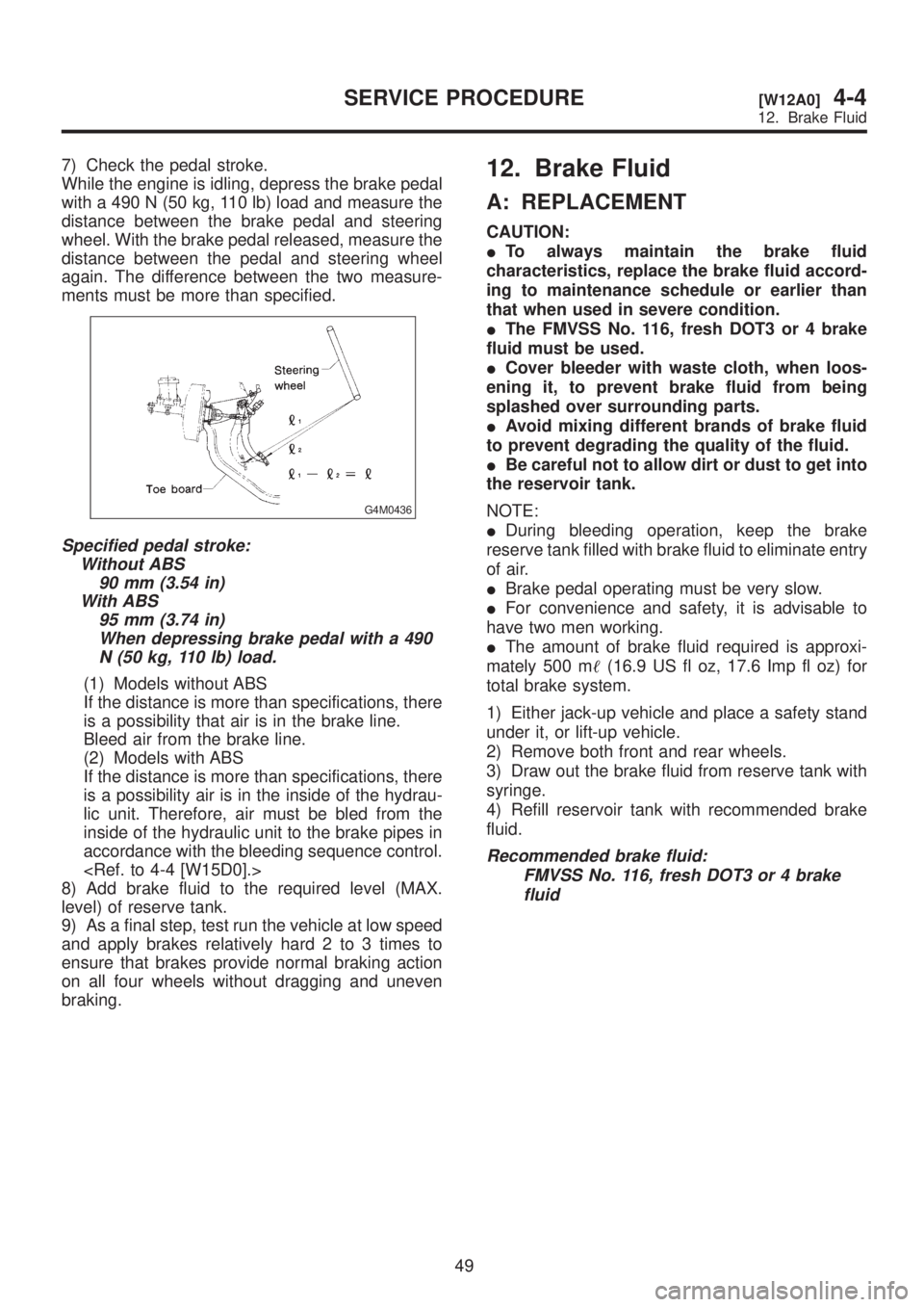
7) Check the pedal stroke.
While the engine is idling, depress the brake pedal
with a 490 N (50 kg, 110 lb) load and measure the
distance between the brake pedal and steering
wheel. With the brake pedal released, measure the
distance between the pedal and steering wheel
again. The difference between the two measure-
ments must be more than specified.
G4M0436
Specified pedal stroke:
Without ABS
90 mm (3.54 in)
With ABS
95 mm (3.74 in)
When depressing brake pedal with a 490
N (50 kg, 110 lb) load.
(1) Models without ABS
If the distance is more than specifications, there
is a possibility that air is in the brake line.
Bleed air from the brake line.
(2) Models with ABS
If the distance is more than specifications, there
is a possibility air is in the inside of the hydrau-
lic unit. Therefore, air must be bled from the
inside of the hydraulic unit to the brake pipes in
accordance with the bleeding sequence control.
8) Add brake fluid to the required level (MAX.
level) of reserve tank.
9) As a final step, test run the vehicle at low speed
and apply brakes relatively hard 2 to 3 times to
ensure that brakes provide normal braking action
on all four wheels without dragging and uneven
braking.
12. Brake Fluid
A: REPLACEMENT
CAUTION:
ITo always maintain the brake fluid
characteristics, replace the brake fluid accord-
ing to maintenance schedule or earlier than
that when used in severe condition.
IThe FMVSS No. 116, fresh DOT3 or 4 brake
fluid must be used.
ICover bleeder with waste cloth, when loos-
ening it, to prevent brake fluid from being
splashed over surrounding parts.
IAvoid mixing different brands of brake fluid
to prevent degrading the quality of the fluid.
IBe careful not to allow dirt or dust to get into
the reservoir tank.
NOTE:
IDuring bleeding operation, keep the brake
reserve tank filled with brake fluid to eliminate entry
of air.
IBrake pedal operating must be very slow.
IFor convenience and safety, it is advisable to
have two men working.
IThe amount of brake fluid required is approxi-
mately 500 m(16.9 US fl oz, 17.6 Imp fl oz) for
total brake system.
1) Either jack-up vehicle and place a safety stand
under it, or lift-up vehicle.
2) Remove both front and rear wheels.
3) Draw out the brake fluid from reserve tank with
syringe.
4) Refill reservoir tank with recommended brake
fluid.
Recommended brake fluid:
FMVSS No. 116, fresh DOT3 or 4 brake
fluid
49
[W12A0]4-4SERVICE PROCEDURE
12. Brake Fluid