1999 SUBARU LEGACY rear
[x] Cancel search: rearPage 855 of 1456
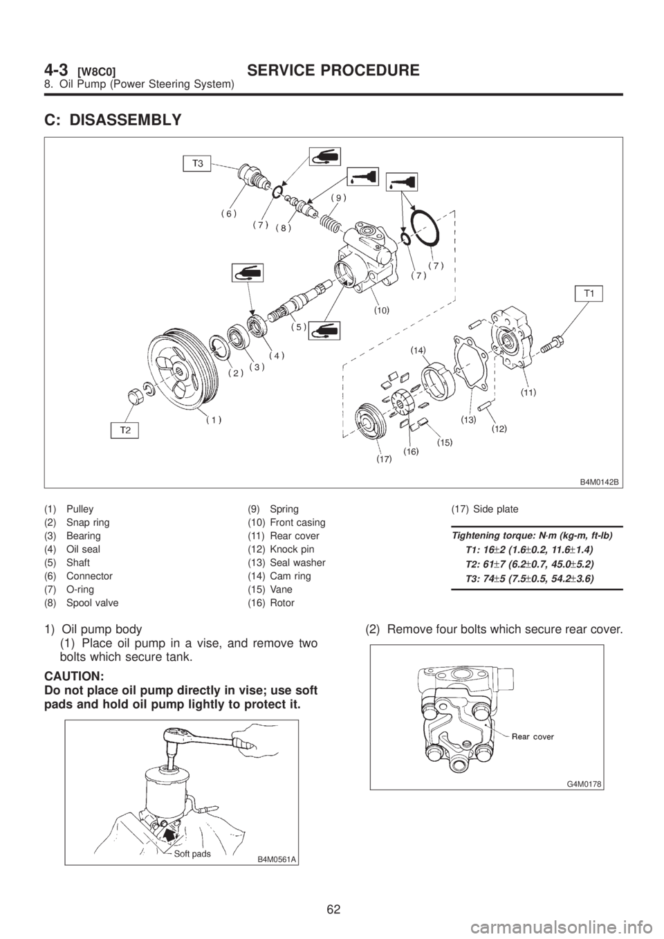
C: DISASSEMBLY
B4M0142B
(1) Pulley
(2) Snap ring
(3) Bearing
(4) Oil seal
(5) Shaft
(6) Connector
(7) O-ring
(8) Spool valve(9) Spring
(10) Front casing
(11) Rear cover
(12) Knock pin
(13) Seal washer
(14) Cam ring
(15) Vane
(16) Rotor(17) Side plate
Tightening torque: N´m (kg-m, ft-lb)
T1:
16±2 (1.6±0.2, 11.6±1.4)
T2:61±7 (6.2±0.7, 45.0±5.2)
T3:74±5 (7.5±0.5, 54.2±3.6)
1) Oil pump body
(1) Place oil pump in a vise, and remove two
bolts which secure tank.
CAUTION:
Do not place oil pump directly in vise; use soft
pads and hold oil pump lightly to protect it.
B4M0561A
(2) Remove four bolts which secure rear cover.
G4M0178
62
4-3[W8C0]SERVICE PROCEDURE
8. Oil Pump (Power Steering System)
Page 857 of 1456
Part name Description Remedy
1. Front casing(1) Damage on body surfaces
(2) Excessive wear on hole, into which spool
valve is inserted.
(3) Wear and damage on cartridge assembly
mounting surface
(4) Wear and damage on surfaces in contact
with shaft and oil sealReplace with a new one together with spool valve
as selective fit is made.
2. Rear cover(1) Damage on body surfaces
(2) Wear and damage on sliding surfacesReplace with a new one.
3. Shaft(1) Shaft bend
(2) Wear and damage on surfaces in contact
with bushing and oil seal
(3) Wear and damage on rotor mounting sur-
faces
(4) Bearing damageReplace with a new one.
4. Side plate Wear and damage on sliding surfaces Replace with a new one.
5. Cam ring Ridge wear on sliding surfaces
If damage is serious, replace with a new car-
tridge assembly. 6. Vane Excessive wear on nose radius and side surfaces
7. Rotor(1) Wear and damage on sliding surfaces
(2) Ridge wear on vane sliding grooves (If light
leaks with vane in slit against light source)
(3) Damage resulting from snap ring removalCorrect with oil stone. If damage is serious,
replace with a new cartridge assembly.
8. Spool valve Damage or burrs on sliding surface peripheryReplace with a new one together with front cas-
ing as selective fit is made.
9. Connector Damage on threads Replace with a new one.
10. Spring Damage Replace with a new one.
11. Bolts and nuts Damage on threads Replace with a new one.
E: ASSEMBLY
1) Reassembly precautions
(1) Whenever O-rings, oil seals, and snap rings
are removed, they must be replaced with new
ones.
(2) Thoroughly wash parts and allow to dry.
They must be kept free from cleaning oil and
dust.
(3) Reassembly procedure must be performed
in clean place. Ensure that parts are kept away
from waste threads or other dust particles.
(4) Cleaning oil tends to stay inside the front
casing. Remove it completely by blowing com-
pressed air.
(5) Ensure that parts are free from rust. (Use
specified power steering fluid for rust prevention
after cleaning and drying.)
(6) Reverse the sequence of disassembly pro-
cedures.
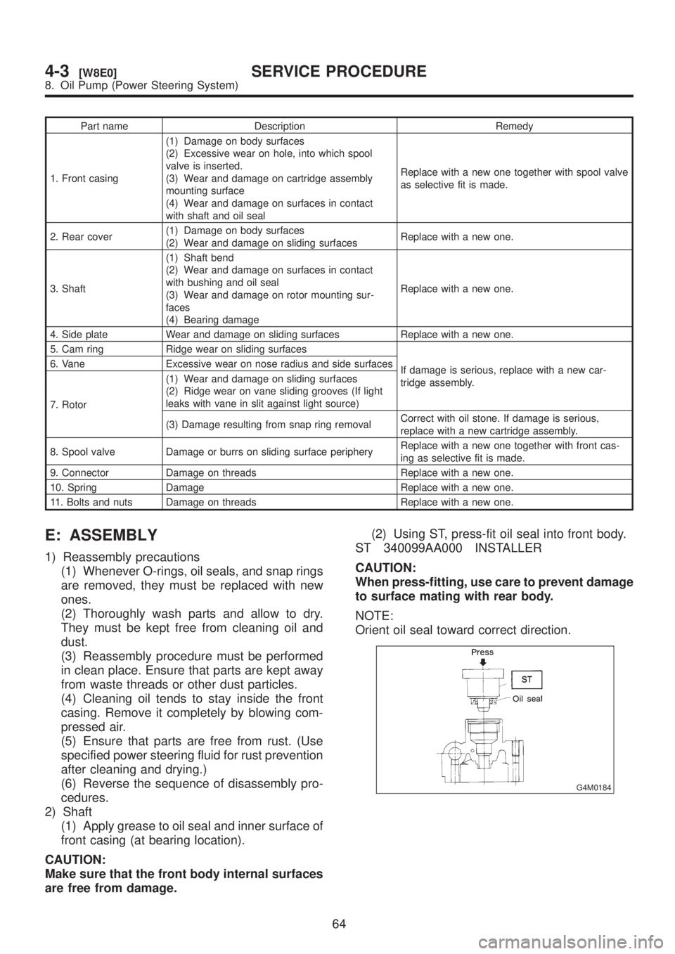
2) Shaft
(1) Apply grease to oil seal and inner surface of
front casing (at bearing location).
CAUTION:
Make sure that the front body internal surfaces
are free from damage.(2) Using ST, press-fit oil seal into front body.
ST 340099AA000 INSTALLER
CAUTION:
When press-fitting, use care to prevent damage
to surface mating with rear body.
NOTE:
Orient oil seal toward correct direction.
G4M0184
64
4-3[W8E0]SERVICE PROCEDURE
8. Oil Pump (Power Steering System)
Page 858 of 1456
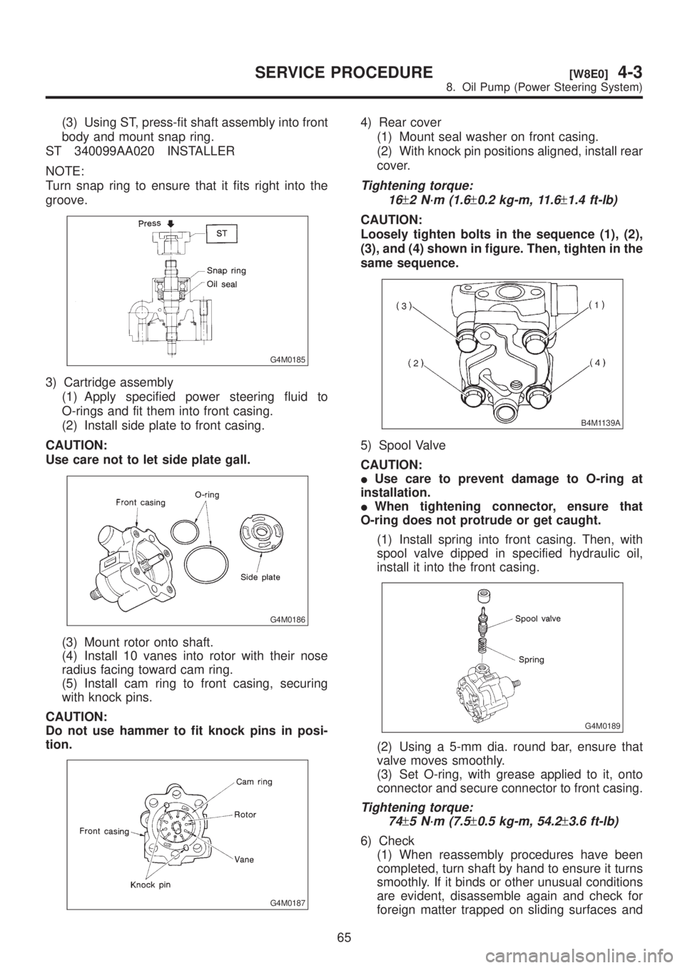
(3) Using ST, press-fit shaft assembly into front
body and mount snap ring.
ST 340099AA020 INSTALLER
NOTE:
Turn snap ring to ensure that it fits right into the
groove.
G4M0185
3) Cartridge assembly
(1) Apply specified power steering fluid to
O-rings and fit them into front casing.
(2) Install side plate to front casing.
CAUTION:
Use care not to let side plate gall.
G4M0186
(3) Mount rotor onto shaft.
(4) Install 10 vanes into rotor with their nose
radius facing toward cam ring.
(5) Install cam ring to front casing, securing
with knock pins.
CAUTION:
Do not use hammer to fit knock pins in posi-
tion.
G4M0187
4) Rear cover
(1) Mount seal washer on front casing.
(2) With knock pin positions aligned, install rear
cover.
Tightening torque:
16
±2 N´m (1.6±0.2 kg-m, 11.6±1.4 ft-lb)
CAUTION:
Loosely tighten bolts in the sequence (1), (2),
(3), and (4) shown in figure. Then, tighten in the
same sequence.
B4M1139A
5) Spool Valve
CAUTION:
IUse care to prevent damage to O-ring at
installation.
IWhen tightening connector, ensure that
O-ring does not protrude or get caught.
(1) Install spring into front casing. Then, with
spool valve dipped in specified hydraulic oil,
install it into the front casing.
G4M0189
(2) Using a 5-mm dia. round bar, ensure that
valve moves smoothly.
(3) Set O-ring, with grease applied to it, onto
connector and secure connector to front casing.
Tightening torque:
74
±5 N´m (7.5±0.5 kg-m, 54.2±3.6 ft-lb)
6) Check
(1) When reassembly procedures have been
completed, turn shaft by hand to ensure it turns
smoothly. If it binds or other unusual conditions
are evident, disassemble again and check for
foreign matter trapped on sliding surfaces and
65
[W8E0]4-3SERVICE PROCEDURE
8. Oil Pump (Power Steering System)
Page 873 of 1456
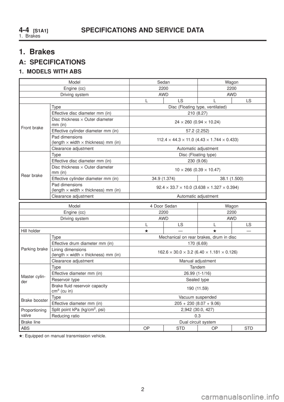
1. Brakes
A: SPECIFICATIONS
1. MODELS WITH ABS
Model Sedan Wagon
Engine (cc) 2200 2200
Driving system AWD AWD
LLSLLS
Front brakeType Disc (Floating type, ventilated)
Effective disc diameter mm (in) 210 (8.27)
Disc thickness´Outer diameter
mm (in)24´260 (0.94´10.24)
Effective cylinder diameter mm (in) 57.2 (2.252)
Pad dimensions
(length´width´thickness) mm (in)112.4´44.3´11.0 (4.43´1.744´0.433)
Clearance adjustment Automatic adjustment
Rear brakeType Disc (Floating type)
Effective disc diameter mm (in) 230 (9.06)
Disc thickness´Outer diameter
mm (in)10´266 (0.39´10.47)
Effective cylinder diameter mm (in) 34.9 (1.374) 38.1 (1.500)
Pad dimensions
(length´width´thickness) mm (in)92.4´33.7´10.0 (3.638´1.327´0.394)
Clearance adjustment Automatic adjustment
Model 4 Door Sedan Wagon
Engine (cc) 2200 2200
Driving system AWD AWD
LLSLLS
Hill holderHÐHÐ
Parking brakeType Mechanical on rear brakes, drum in disc
Effective drum diameter mm (in) 170 (6.69)
Lining dimensions
(length´width´thickness) mm (in)162.6´30.0´3.2 (6.40´1.181´0.126)
Clearance adjustment Manual adjustment
Master cylin-
derType Tandem
Effective diameter mm (in) 26.99 (1-1/16)
Reservoir type Sealed type
Brake fluid reservoir capacity
cm
3(cu in)190 (11.59)
Brake boosterType Vacuum suspended
Effective diameter mm (in) 205 + 230 (8.07 + 9.06)
Proportioning
valveSplit point kPa (kg/cm
2, psi) 2,942 (30.0, 427)
Reducing ratio 0.3
Brake lineDual circuit system
ABS OP STD OP STD
H: Equipped on manual transmission vehicle.
2
4-4[S1A1]SPECIFICATIONS AND SERVICE DATA
1. Brakes
Page 874 of 1456
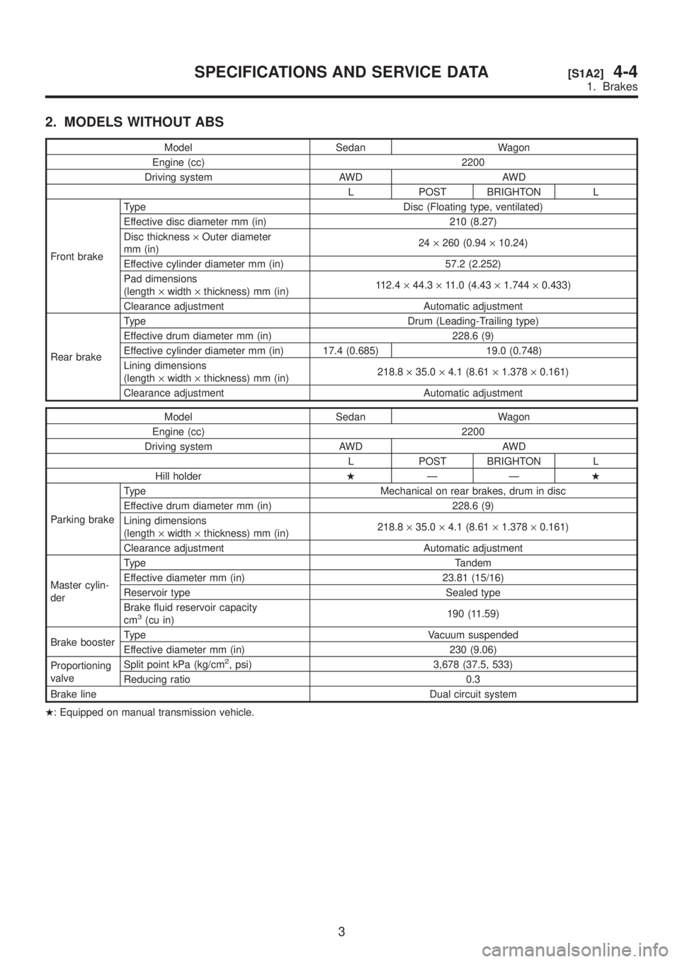
2. MODELS WITHOUT ABS
Model Sedan Wagon
Engine (cc) 2200
Driving system AWD AWD
L POST BRIGHTON L
Front brakeType Disc (Floating type, ventilated)
Effective disc diameter mm (in) 210 (8.27)
Disc thickness´Outer diameter
mm (in)24´260 (0.94´10.24)
Effective cylinder diameter mm (in) 57.2 (2.252)
Pad dimensions
(length´width´thickness) mm (in)112.4´44.3´11.0 (4.43´1.744´0.433)
Clearance adjustment Automatic adjustment
Rear brakeType Drum (Leading-Trailing type)
Effective drum diameter mm (in) 228.6 (9)
Effective cylinder diameter mm (in) 17.4 (0.685) 19.0 (0.748)
Lining dimensions
(length´width´thickness) mm (in)218.8´35.0´4.1 (8.61´1.378´0.161)
Clearance adjustment Automatic adjustment
Model Sedan Wagon
Engine (cc) 2200
Driving system AWD AWD
L POST BRIGHTON L
Hill holderHÐÐH
Parking brakeType Mechanical on rear brakes, drum in disc
Effective drum diameter mm (in) 228.6 (9)
Lining dimensions
(length´width´thickness) mm (in)218.8´35.0´4.1 (8.61´1.378´0.161)
Clearance adjustment Automatic adjustment
Master cylin-
derType Tandem
Effective diameter mm (in) 23.81 (15/16)
Reservoir type Sealed type
Brake fluid reservoir capacity
cm
3(cu in)190 (11.59)
Brake boosterType Vacuum suspended
Effective diameter mm (in) 230 (9.06)
Proportioning
valveSplit point kPa (kg/cm
2, psi) 3,678 (37.5, 533)
Reducing ratio 0.3
Brake lineDual circuit system
H: Equipped on manual transmission vehicle.
3
[S1A2]4-4SPECIFICATIONS AND SERVICE DATA
1. Brakes
Page 875 of 1456
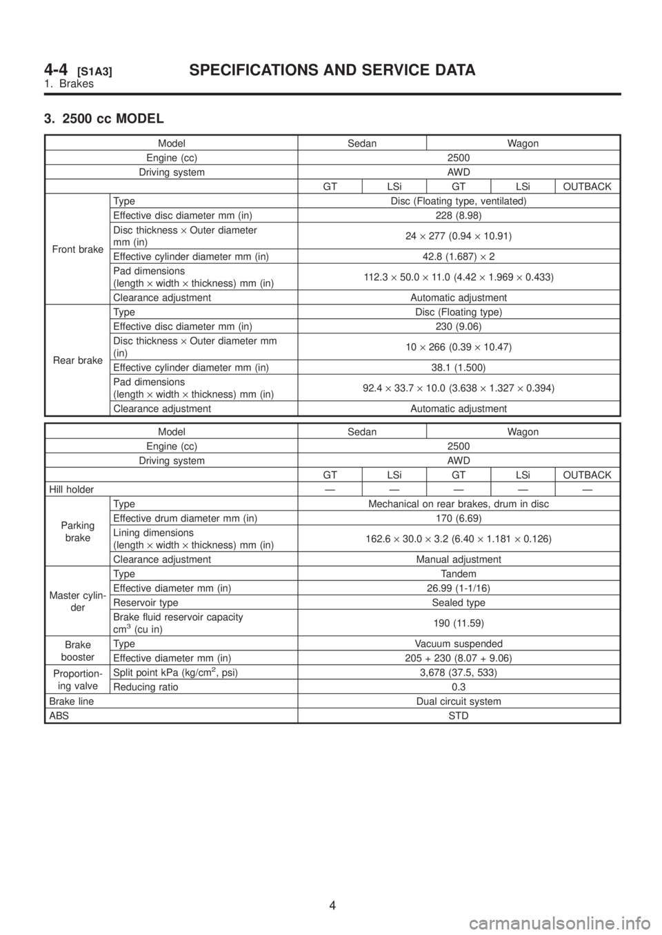
3. 2500 cc MODEL
Model Sedan Wagon
Engine (cc) 2500
Driving system AWD
GT LSi GT LSi OUTBACK
Front brakeType Disc (Floating type, ventilated)
Effective disc diameter mm (in) 228 (8.98)
Disc thickness´Outer diameter
mm (in)24´277 (0.94´10.91)
Effective cylinder diameter mm (in) 42.8 (1.687)´2
Pad dimensions
(length´width´thickness) mm (in)112.3´50.0´11.0 (4.42´1.969´0.433)
Clearance adjustment Automatic adjustment
Rear brakeType Disc (Floating type)
Effective disc diameter mm (in) 230 (9.06)
Disc thickness´Outer diameter mm
(in)10´266 (0.39´10.47)
Effective cylinder diameter mm (in) 38.1 (1.500)
Pad dimensions
(length´width´thickness) mm (in)92.4´33.7´10.0 (3.638´1.327´0.394)
Clearance adjustment Automatic adjustment
Model Sedan Wagon
Engine (cc) 2500
Driving system AWD
GT LSi GT LSi OUTBACK
Hill holderÐÐÐÐÐ
Parking
brakeType Mechanical on rear brakes, drum in disc
Effective drum diameter mm (in) 170 (6.69)
Lining dimensions
(length´width´thickness) mm (in)162.6´30.0´3.2 (6.40´1.181´0.126)
Clearance adjustment Manual adjustment
Master cylin-
derType Tandem
Effective diameter mm (in) 26.99 (1-1/16)
Reservoir type Sealed type
Brake fluid reservoir capacity
cm
3(cu in)190 (11.59)
Brake
boosterType Vacuum suspended
Effective diameter mm (in) 205 + 230 (8.07 + 9.06)
Proportion-
ing valveSplit point kPa (kg/cm
2, psi) 3,678 (37.5, 533)
Reducing ratio 0.3
Brake lineDual circuit system
ABSSTD
4
4-4[S1A3]SPECIFICATIONS AND SERVICE DATA
1. Brakes
Page 876 of 1456
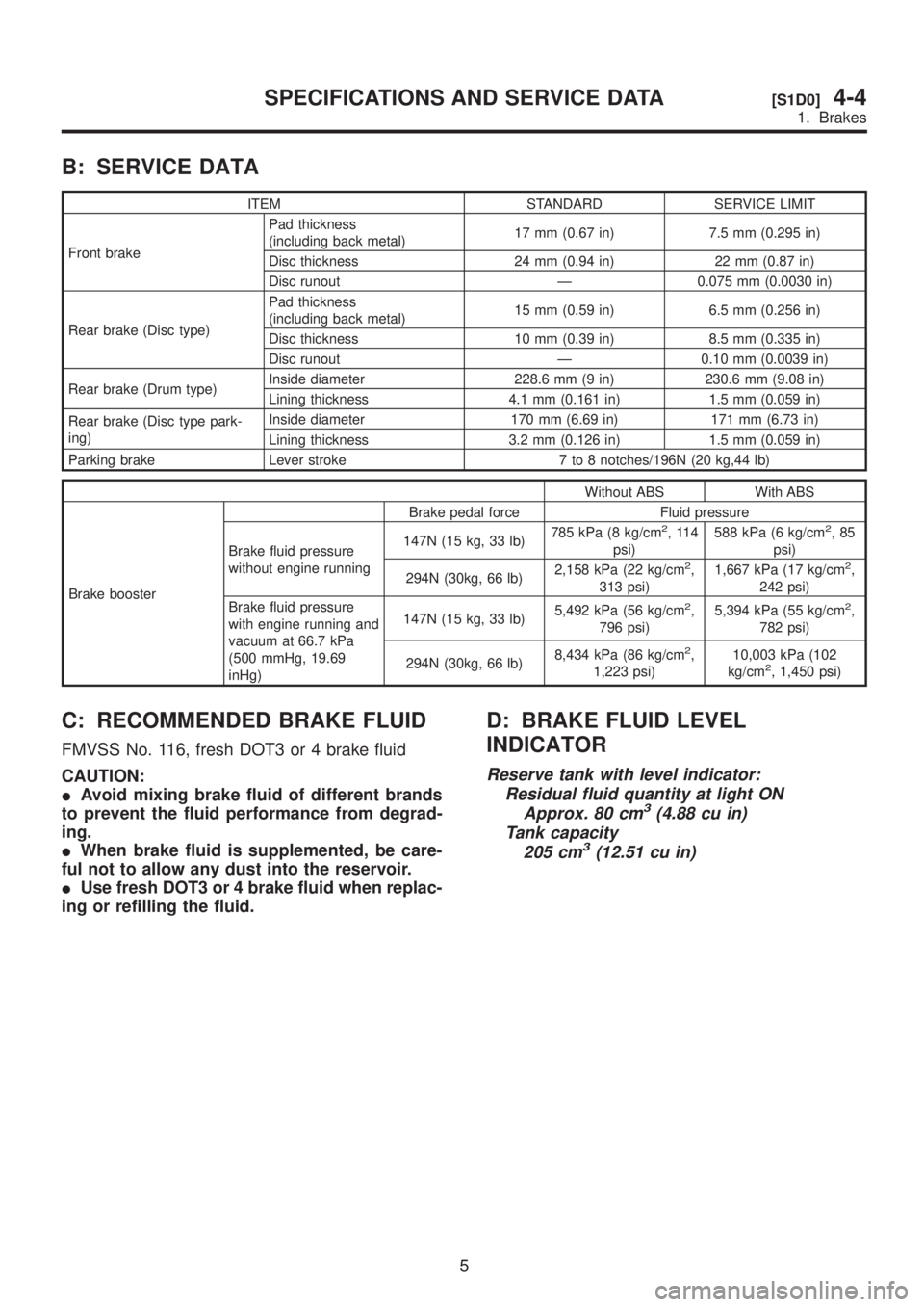
B: SERVICE DATA
ITEM STANDARD SERVICE LIMIT
Front brakePad thickness
(including back metal)17 mm (0.67 in) 7.5 mm (0.295 in)
Disc thickness 24 mm (0.94 in) 22 mm (0.87 in)
Disc runout Ð 0.075 mm (0.0030 in)
Rear brake (Disc type)Pad thickness
(including back metal)15 mm (0.59 in) 6.5 mm (0.256 in)
Disc thickness 10 mm (0.39 in) 8.5 mm (0.335 in)
Disc runout Ð 0.10 mm (0.0039 in)
Rear brake (Drum type)Inside diameter 228.6 mm (9 in) 230.6 mm (9.08 in)
Lining thickness 4.1 mm (0.161 in) 1.5 mm (0.059 in)
Rear brake (Disc type park-
ing)Inside diameter 170 mm (6.69 in) 171 mm (6.73 in)
Lining thickness 3.2 mm (0.126 in) 1.5 mm (0.059 in)
Parking brake Lever stroke 7 to 8 notches/196N (20 kg,44 lb)
Without ABS With ABS
Brake boosterBrake pedal force Fluid pressure
Brake fluid pressure
without engine running147N (15 kg, 33 lb)785 kPa (8 kg/cm
2,114
psi)588 kPa (6 kg/cm2,85
psi)
294N (30kg, 66 lb)2,158 kPa (22 kg/cm
2,
313 psi)1,667 kPa (17 kg/cm2,
242 psi)
Brake fluid pressure
with engine running and
vacuum at 66.7 kPa
(500 mmHg, 19.69
inHg)147N (15 kg, 33 lb)5,492 kPa (56 kg/cm
2,
796 psi)5,394 kPa (55 kg/cm2,
782 psi)
294N (30kg, 66 lb)8,434 kPa (86 kg/cm
2,
1,223 psi)10,003 kPa (102
kg/cm2, 1,450 psi)
C: RECOMMENDED BRAKE FLUID
FMVSS No. 116, fresh DOT3 or 4 brake fluid
CAUTION:
IAvoid mixing brake fluid of different brands
to prevent the fluid performance from degrad-
ing.
IWhen brake fluid is supplemented, be care-
ful not to allow any dust into the reservoir.
IUse fresh DOT3 or 4 brake fluid when replac-
ing or refilling the fluid.
D: BRAKE FLUID LEVEL
INDICATOR
Reserve tank with level indicator:
Residual fluid quantity at light ON
Approx. 80 cm
3(4.88 cu in)
Tank capacity
205 cm
3(12.51 cu in)
5
[S1D0]4-4SPECIFICATIONS AND SERVICE DATA
1. Brakes
Page 879 of 1456
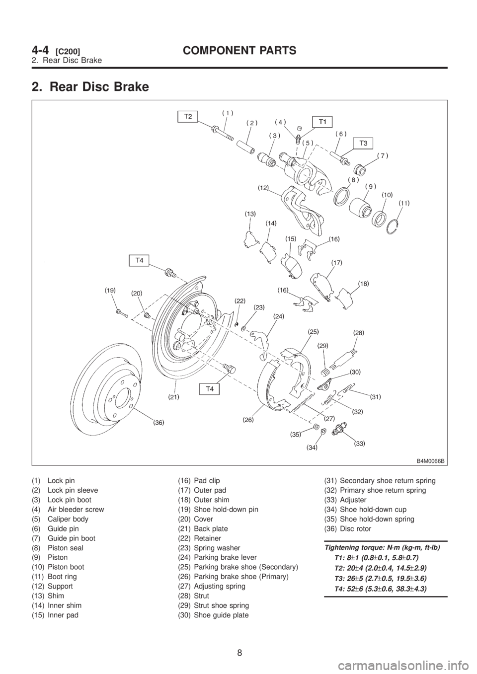
2. Rear Disc Brake
B4M0066B
(1) Lock pin
(2) Lock pin sleeve
(3) Lock pin boot
(4) Air bleeder screw
(5) Caliper body
(6) Guide pin
(7) Guide pin boot
(8) Piston seal
(9) Piston
(10) Piston boot
(11) Boot ring
(12) Support
(13) Shim
(14) Inner shim
(15) Inner pad(16) Pad clip
(17) Outer pad
(18) Outer shim
(19) Shoe hold-down pin
(20) Cover
(21) Back plate
(22) Retainer
(23) Spring washer
(24) Parking brake lever
(25) Parking brake shoe (Secondary)
(26) Parking brake shoe (Primary)
(27) Adjusting spring
(28) Strut
(29) Strut shoe spring
(30) Shoe guide plate(31) Secondary shoe return spring
(32) Primary shoe return spring
(33) Adjuster
(34) Shoe hold-down cup
(35) Shoe hold-down spring
(36) Disc rotor
Tightening torque: N´m (kg-m, ft-lb)
T1:
8±1 (0.8±0.1, 5.8±0.7)
T2:20±4 (2.0±0.4, 14.5±2.9)
T3:26±5 (2.7±0.5, 19.5±3.6)
T4:52±6 (5.3±0.6, 38.3±4.3)
8
4-4[C200]COMPONENT PARTS
2. Rear Disc Brake