Page 780 of 1456

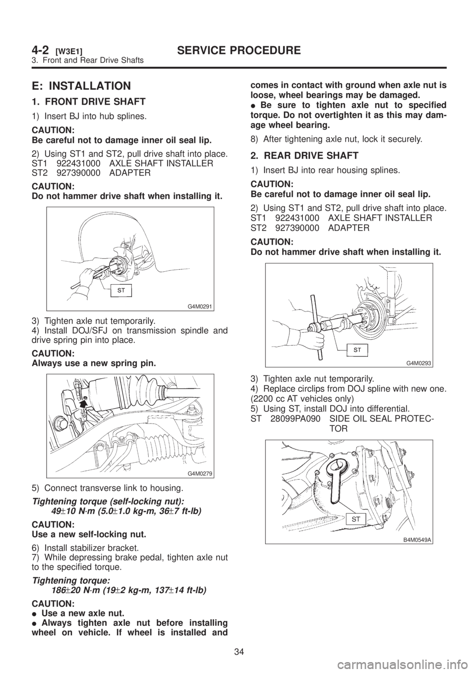
E: INSTALLATION
1. FRONT DRIVE SHAFT
1) Insert BJ into hub splines.
CAUTION:
Be careful not to damage inner oil seal lip.
2) Using ST1 and ST2, pull drive shaft into place.
ST1 922431000 AXLE SHAFT INSTALLER
ST2 927390000 ADAPTER
CAUTION:
Do not hammer drive shaft when installing it.
G4M0291
3) Tighten axle nut temporarily.
4) Install DOJ/SFJ on transmission spindle and
drive spring pin into place.
CAUTION:
Always use a new spring pin.
G4M0279
5) Connect transverse link to housing.
Tightening torque (self-locking nut):
49
±10 N´m (5.0±1.0 kg-m, 36±7 ft-lb)
CAUTION:
Use a new self-locking nut.
6) Install stabilizer bracket.
7) While depressing brake pedal, tighten axle nut
to the specified torque.
Tightening torque:
186
±20 N´m (19±2 kg-m, 137±14 ft-lb)
CAUTION:
IUse a new axle nut.
IAlways tighten axle nut before installing
wheel on vehicle. If wheel is installed andcomes in contact with ground when axle nut is
loose, wheel bearings may be damaged.
IBe sure to tighten axle nut to specified
torque. Do not overtighten it as this may dam-
age wheel bearing.
8) After tightening axle nut, lock it securely.
2. REAR DRIVE SHAFT
1) Insert BJ into rear housing splines.
CAUTION:
Be careful not to damage inner oil seal lip.
2) Using ST1 and ST2, pull drive shaft into place.
ST1 922431000 AXLE SHAFT INSTALLER
ST2 927390000 ADAPTER
CAUTION:
Do not hammer drive shaft when installing it.
G4M0293
3) Tighten axle nut temporarily.
4) Replace circlips from DOJ spline with new one.
(2200 cc AT vehicles only)
5) Using ST, install DOJ into differential.
ST 28099PA090 SIDE OIL SEAL PROTEC-
TOR
B4M0549A
34
4-2[W3E1]SERVICE PROCEDURE
3. Front and Rear Drive Shafts
Page 781 of 1456

6) Insert DOJ spline end into bore of side oil seal,
and remove ST.
CAUTION:
Do not allow DOJ splines to damage side oil
seal.
ST 28099PA090 SIDE OIL SEAL PROTEC-
TOR
B4M0550A
7) Align DOJ and differential splines.
8) Push housing to insert DOJ into differential.
NOTE:
Make sure DOJ is inserted properly.
G3M0050
9) Connect crossmember reinforcement lower to
crossmember (4 door model only).
10) Connect rear housing assembly to trailing link
assembly, and tighten self-locking nut.
Tightening torque:
11 3
±15 N´m (11.5±1.5 kg-m, 83±11 ft-lb)
11) Connect rear housing assembly to lateral link
assembly, and tighten self-locking nut.
Tightening torque:
137
±20 N´m (14±2 kg-m, 101±14 ft-lb)
12) Install stabilizer bracket.
13) While depressing brake pedal, tighten axle nut
using a socket wrench.
Tightening torque:
186
±20 N´m (19±2 kg-m, 137±14 ft-lb)
CAUTION:
IUse a new axle nut.
IAlways tighten axle nut before installing
wheel on vehicle. If wheel is installed and
comes in contact with ground when axle nut is
loose, wheel bearings may be damaged.
IBe sure to tighten axle nut to specified
torque. Do not overtighten it as this may dam-
age wheel bearing.
14) After tightening axle nut, lock it securely.
35
[W3E2]4-2SERVICE PROCEDURE
3. Front and Rear Drive Shafts
Page 782 of 1456

4. Replacement of Front SFJ,
DOJ and BJ Boots
A: REMOVAL
1) Disconnect ground cable from battery.
2) Jack-up vehicle, support it with safety stands
(rigid racks), and remove front wheel cap and
wheels.
NOTE:
Do not remove axle nut.
3) Remove stabilizer link.
4) Disconnect transverse link from housing.
5) Remove spring pin which secures transmission
spindle to DOJ/SFJ.
CAUTION:
Use a new spring pin.
G4M0279
6) Remove SFJ, DOJ and BJ boots from drive
shaft. or
[W3B2].>
B: INSTALLATION
1) Install SFJ, DOJ and BJ boots to drive shaft.
or
2) Install DOJ/SFJ on transmission spindle and
drive spring pin into place.
CAUTION:
Always use a new spring pin.
G4M0279
3) Connect transverse link to housing.
4) Install stabilizer link.
5. Replacement of Rear DOJ
and BJ Boots
A: REMOVAL
1) Disconnect ground cable from battery.
2) Lift-up vehicle, and remove rear wheel cap and
wheels.
NOTE:
Axle nut need not be removed.
3) Remove ABS sensor clamps and parking brake
cable bracket.
4) Disconnect stabilizer link from lateral link.
5) Remove bolts which secure lateral link assem-
bly to rear housing.
6) Remove bolts which secure trailing link assem-
bly to rear housing.
7) Remove crossmember reinforcement lower
from crossmember (4 door model only).
8) Remove DOJ from rear differential using ST.
(Except 2200 cc AT vehicles)
ST 28099PA100 DRIVE SHAFT REMOVER
CAUTION:
Do not remove circlip attached to inside of dif-
ferential.
G4M0994
CAUTION:
Be careful not to damage side bearing retainer.
Always use bolt as shown in figure, as support-
ing point for ST during removal.
ST 28099PA100 DRIVE SHAFT REMOVER
G4M0995
36
4-2[W4A0]SERVICE PROCEDURE
4. Replacement of Front SFJ, DOJ and BJ Boots
Page 783 of 1456

4. Replacement of Front SFJ,
DOJ and BJ Boots
A: REMOVAL
1) Disconnect ground cable from battery.
2) Jack-up vehicle, support it with safety stands
(rigid racks), and remove front wheel cap and
wheels.
NOTE:
Do not remove axle nut.
3) Remove stabilizer link.
4) Disconnect transverse link from housing.
5) Remove spring pin which secures transmission
spindle to DOJ/SFJ.
CAUTION:
Use a new spring pin.
G4M0279
6) Remove SFJ, DOJ and BJ boots from drive
shaft. or
[W3B2].>
B: INSTALLATION
1) Install SFJ, DOJ and BJ boots to drive shaft.
or
2) Install DOJ/SFJ on transmission spindle and
drive spring pin into place.
CAUTION:
Always use a new spring pin.
G4M0279
3) Connect transverse link to housing.
4) Install stabilizer link.
5. Replacement of Rear DOJ
and BJ Boots
A: REMOVAL
1) Disconnect ground cable from battery.
2) Lift-up vehicle, and remove rear wheel cap and
wheels.
NOTE:
Axle nut need not be removed.
3) Remove ABS sensor clamps and parking brake
cable bracket.
4) Disconnect stabilizer link from lateral link.
5) Remove bolts which secure lateral link assem-
bly to rear housing.
6) Remove bolts which secure trailing link assem-
bly to rear housing.
7) Remove crossmember reinforcement lower
from crossmember (4 door model only).
8) Remove DOJ from rear differential using ST.
(Except 2200 cc AT vehicles)
ST 28099PA100 DRIVE SHAFT REMOVER
CAUTION:
Do not remove circlip attached to inside of dif-
ferential.
G4M0994
CAUTION:
Be careful not to damage side bearing retainer.
Always use bolt as shown in figure, as support-
ing point for ST during removal.
ST 28099PA100 DRIVE SHAFT REMOVER
G4M0995
36
4-2[W4A0]SERVICE PROCEDURE
4. Replacement of Front SFJ, DOJ and BJ Boots
Page 784 of 1456

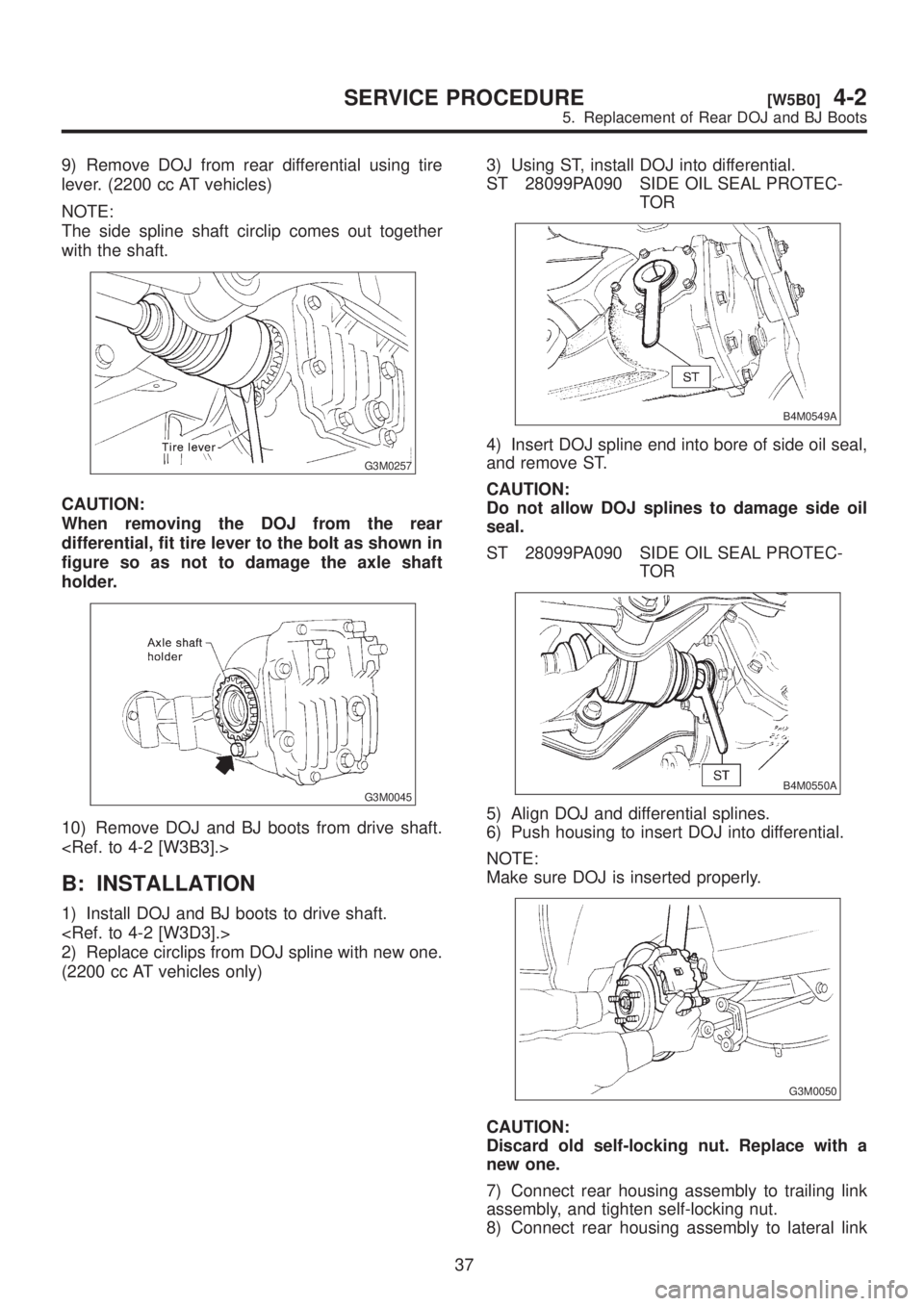
9) Remove DOJ from rear differential using tire
lever. (2200 cc AT vehicles)
NOTE:
The side spline shaft circlip comes out together
with the shaft.
G3M0257
CAUTION:
When removing the DOJ from the rear
differential, fit tire lever to the bolt as shown in
figure so as not to damage the axle shaft
holder.
G3M0045
10) Remove DOJ and BJ boots from drive shaft.
B: INSTALLATION
1) Install DOJ and BJ boots to drive shaft.
2) Replace circlips from DOJ spline with new one.
(2200 cc AT vehicles only)3) Using ST, install DOJ into differential.
ST 28099PA090 SIDE OIL SEAL PROTEC-
TOR
B4M0549A
4) Insert DOJ spline end into bore of side oil seal,
and remove ST.
CAUTION:
Do not allow DOJ splines to damage side oil
seal.
ST 28099PA090 SIDE OIL SEAL PROTEC-
TOR
B4M0550A
5) Align DOJ and differential splines.
6) Push housing to insert DOJ into differential.
NOTE:
Make sure DOJ is inserted properly.
G3M0050
CAUTION:
Discard old self-locking nut. Replace with a
new one.
7) Connect rear housing assembly to trailing link
assembly, and tighten self-locking nut.
8) Connect rear housing assembly to lateral link
37
[W5B0]4-2SERVICE PROCEDURE
5. Replacement of Rear DOJ and BJ Boots
Page 788 of 1456

8. Aluminum Wheel
A: INSPECTION
Inspection for aluminum wheels is basically the
same as the one for steel wheels. However, check
the rim flange for cracks or damage, and replace
(not repair) aluminum wheel if air leakage is found.
B: PRECAUTIONS
Aluminum wheels are easily scratched. To main-
tain their appearance and safety, do the following:
1) Do not damage aluminum wheels during
removal, disassembly, installation, wheel
balancing, etc. After removing aluminum wheels,
place them on a rubber mat, etc.
2) While vehicle is being driven, be careful not to
ride over sharp obstacles or allow aluminum
wheels to contact the shoulder of the road.
3) When installing tire chain, be sure to install it
properly not to have a slack; otherwise it may hit
wheel while driving.
4) When washing aluminum wheel, use neutral
synthetic detergent and water. Avoid using the
cleanser including abrasive, hard brushes or an
automatic car washer.
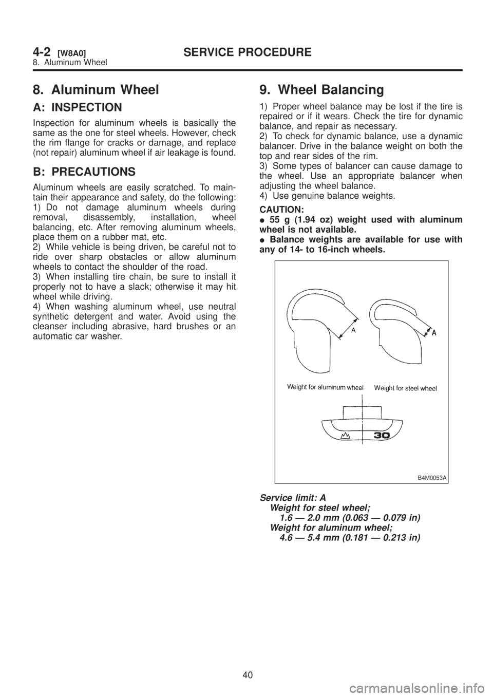
9. Wheel Balancing
1) Proper wheel balance may be lost if the tire is
repaired or if it wears. Check the tire for dynamic
balance, and repair as necessary.
2) To check for dynamic balance, use a dynamic
balancer. Drive in the balance weight on both the
top and rear sides of the rim.
3) Some types of balancer can cause damage to
the wheel. Use an appropriate balancer when
adjusting the wheel balance.
4) Use genuine balance weights.
CAUTION:
I55 g (1.94 oz) weight used with aluminum
wheel is not available.
IBalance weights are available for use with
any of 14- to 16-inch wheels.
B4M0053A
Service limit: A
Weight for steel wheel;
1.6 Ð 2.0 mm (0.063 Ð 0.079 in)
Weight for aluminum wheel;
4.6 Ð 5.4 mm (0.181 Ð 0.213 in)
40
4-2[W8A0]SERVICE PROCEDURE
8. Aluminum Wheel
Page 789 of 1456

8. Aluminum Wheel
A: INSPECTION
Inspection for aluminum wheels is basically the
same as the one for steel wheels. However, check
the rim flange for cracks or damage, and replace
(not repair) aluminum wheel if air leakage is found.
B: PRECAUTIONS
Aluminum wheels are easily scratched. To main-
tain their appearance and safety, do the following:
1) Do not damage aluminum wheels during
removal, disassembly, installation, wheel
balancing, etc. After removing aluminum wheels,
place them on a rubber mat, etc.
2) While vehicle is being driven, be careful not to
ride over sharp obstacles or allow aluminum
wheels to contact the shoulder of the road.
3) When installing tire chain, be sure to install it
properly not to have a slack; otherwise it may hit
wheel while driving.
4) When washing aluminum wheel, use neutral
synthetic detergent and water. Avoid using the
cleanser including abrasive, hard brushes or an
automatic car washer.
9. Wheel Balancing
1) Proper wheel balance may be lost if the tire is
repaired or if it wears. Check the tire for dynamic
balance, and repair as necessary.
2) To check for dynamic balance, use a dynamic
balancer. Drive in the balance weight on both the
top and rear sides of the rim.
3) Some types of balancer can cause damage to
the wheel. Use an appropriate balancer when
adjusting the wheel balance.
4) Use genuine balance weights.
CAUTION:
I55 g (1.94 oz) weight used with aluminum
wheel is not available.
IBalance weights are available for use with
any of 14- to 16-inch wheels.
B4M0053A
Service limit: A
Weight for steel wheel;
1.6 Ð 2.0 mm (0.063 Ð 0.079 in)
Weight for aluminum wheel;
4.6 Ð 5.4 mm (0.181 Ð 0.213 in)
40
4-2[W8A0]SERVICE PROCEDURE
8. Aluminum Wheel
Page 800 of 1456
3. Power Steering Oil Pump
B4M0123B
(1) Pulley
(2) Snap ring
(3) Bearing
(4) Oil seal
(5) Shaft
(6) Connector
(7) O-ring
(8) Spool valve(9) Spring
(10) Front casing
(11) Rear cover
(12) Gasket
(13) Knock pin
(14) Cam ring
(15) Vane
(16) Rotor(17) Side plate
Tightening torque: N´m (kg-m, ft-lb)
T1:
16±2 (1.6±0.2, 11.6±1.4)
T2:61±7 (6.2±0.7, 44.8±5.1)
T3:74±5 (7.5±0.5, 54.2±3.6)
9
[C300]4-3COMPONENT PARTS
3. Power Steering Oil Pump