Page 819 of 1456

1) Disconnect battery negative terminal.
2) Disconnect both oxygen sensor and exhaust
gas temperature warning sensor connectors from
front exhaust pipe assembly.
WARNING:
Be careful as exhaust pipe is hot.
3) Raise vehicle with a jack and remove front
wheel.
4) Disconnect front exhaust pipe assembly.
5) Remove cotter pin and castle nut. Using a
puller, remove tie-rod end from knuckle arm.
G4M0097
6) Remove jack-up plate and stabilizer.
G4M0098
7) Disconnect one pipe joint A from center of gear-
box assembly, and connect a vinyl hose to it. While
turning steering wheel to the left and right, drain
fluid through the hose. Similarly, drain fluid from
the other pipe joint B.
G4M0786
8) Remove lower and upper bolts from universal
joint, and remove universal joint in the upward
direction.
NOTE:
Scribe alignment marks on universal joint so that it
can be reassembled at the original serration.
G4M0787
9) Remove flare nuts from control valve of gear-
box assembly, and disconnect upper and lower
hoses B and A.
CAUTION:
IAlways disconnect hoses B and A in that
order.
IBe careful not to damage the hoses during
removal.
10) Remove bolts securing gearbox to
crossmember, and detach gearbox.
B: DISASSEMBLY
1) Disconnect four pipes from gearbox.
2) Secure gearbox removed from vehicle in vice
using ST.
ST 926200000 STAND
CAUTION:
Secure the gearbox assembly in a vice using
the ST as shown. Do not attempt to secure it
without this ST.
G4M0788
27
[W4B0]4-3SERVICE PROCEDURE
4. Steering Gearbox (Power Steering System) [RHD model]
Page 820 of 1456

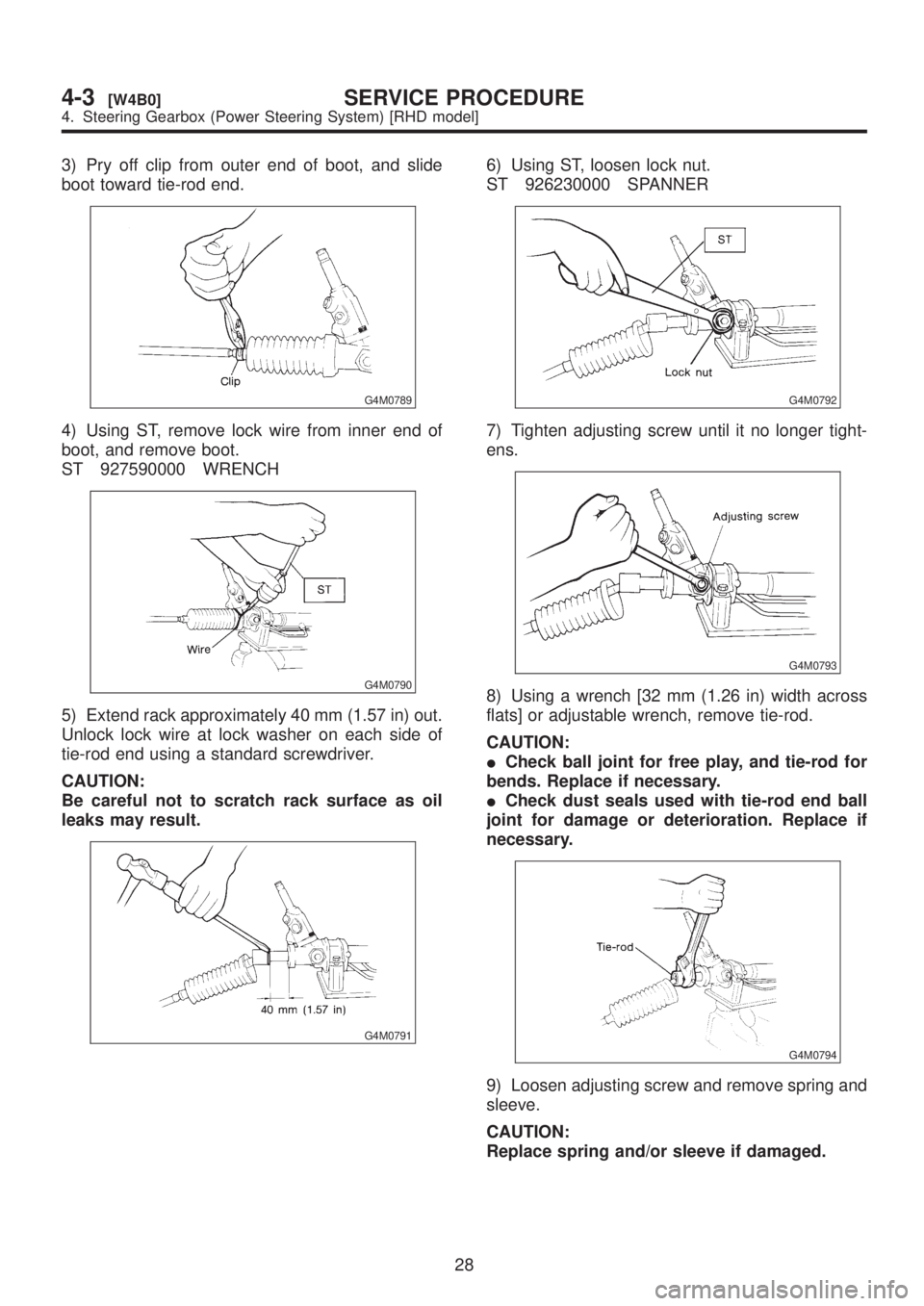
3) Pry off clip from outer end of boot, and slide
boot toward tie-rod end.
G4M0789
4) Using ST, remove lock wire from inner end of
boot, and remove boot.
ST 927590000 WRENCH
G4M0790
5) Extend rack approximately 40 mm (1.57 in) out.
Unlock lock wire at lock washer on each side of
tie-rod end using a standard screwdriver.
CAUTION:
Be careful not to scratch rack surface as oil
leaks may result.
G4M0791
6) Using ST, loosen lock nut.
ST 926230000 SPANNER
G4M0792
7) Tighten adjusting screw until it no longer tight-
ens.
G4M0793
8) Using a wrench [32 mm (1.26 in) width across
flats] or adjustable wrench, remove tie-rod.
CAUTION:
ICheck ball joint for free play, and tie-rod for
bends. Replace if necessary.
ICheck dust seals used with tie-rod end ball
joint for damage or deterioration. Replace if
necessary.
G4M0794
9) Loosen adjusting screw and remove spring and
sleeve.
CAUTION:
Replace spring and/or sleeve if damaged.
28
4-3[W4B0]SERVICE PROCEDURE
4. Steering Gearbox (Power Steering System) [RHD model]
Page 821 of 1456

10) Disconnect pipes A and B from steering body
and control valve housing.
CAUTION:
Replace pipes and/or flare nuts if damaged.
G4M0795
C: INSPECTION
1) Clean all disassembled parts, and check for
wear, damage, or any other faults, then repair or
replace as necessary.
2) When disassembling, check inside of gearbox
for water. If any water is found, carefully check boot
for damage, input shaft dust seal, adjusting screw
and boot clips for poor sealing. If faulty, replace
with new parts.
No. Parts Inspection Corrective action
1 Input shaft(1) Bend of input shaft
(2) Damage on serrationIf bend or damage is excessive, replace
entire gearbox.
2 Dust seal(1) Crack or damage
(2) WearIf outer wall slips, lip is worn out or damage
is found, replace it with new one.
3 Rack and pinion Poor mating of rack with pinion(1) Adjust backlash properly.
By measuring turning torque of gearbox
and sliding resistance of rack, check if rack
and pinion engage uniformly and smoothly
with each other.
(2) Keeping rack pulled out all the way so
that all teeth emerge, check teeth for dam-
age.
Even if abnormality is found in either (1) or
(2), replace entire gearbox.
4 Gearbox unit(1) Bend of rack shaft
(2) Bend of cylinder portion
(3) Crack or damage on cast iron portionReplace gearbox with new one.
(4) Wear or damage on rack bushIf free play of rack shaft in radial direction is
out of the specified range, replace gearbox
with new one.
(5) Wear on input shaft bearingIf free plays of input shaft in radial and axial
directions are out of the specified ranges,
replace gearbox with new one.
5 Boot Crack, damage or deterioration Replace.
6 Tie-rod(1) Looseness of ball joint
(2) Bend of tie-rodReplace.
7 Tie-rod end Damage or deterioration on dust seal Replace.
8 Adjusting screw spring Deterioration Replace.
9 Boot clip Deterioration Replace.
10 Sleeve Damage Replace.
11 Pipes(1) Damage to flared surface
(2) Damage to flare nut
(3) Damage to pipe
(4) Damage to O-ringReplace.
29
[W4C0]4-3SERVICE PROCEDURE
4. Steering Gearbox (Power Steering System) [RHD model]
Page 822 of 1456
1. SERVICE LIMIT
Make a measurement as shown in the figures. If it
exceeds the specified service limit, adjust or
replace.
NOTE:
When making a measurement, vise gearbox by
using ST. Never vise gearbox by inserting alumi-
num plates, etc. between vise and gearbox.
ST 926200000 STAND
Sliding resistance of rack shaft:
Service limit
304 N (31 kg, 68 lb) or less
Difference between left and right sliding
resistance
Less than 20%
G4M0796
G4M0797
2. RACK SHAFT PLAY IN RADIAL
DIRECTION
Right-turn steering:
Service limit
Less than 0.4 mm (0.016 in) (direction
)
Less than 0.6 mm (0.024 in) (direction
)
On condition
L: 5 mm (0.20 in)
P: 98 N (10 kg, 22 lb)
G4M0798
Left-turn steering:
Service limit
Less than 0.4 mm (0.016 in)
(direction
and)
On condition
L: 5 mm (0.20 in)
P: 98 N (10 kg, 22 lb)
G4M0799
30
4-3[W4C1]SERVICE PROCEDURE
4. Steering Gearbox (Power Steering System) [RHD model]
Page 823 of 1456

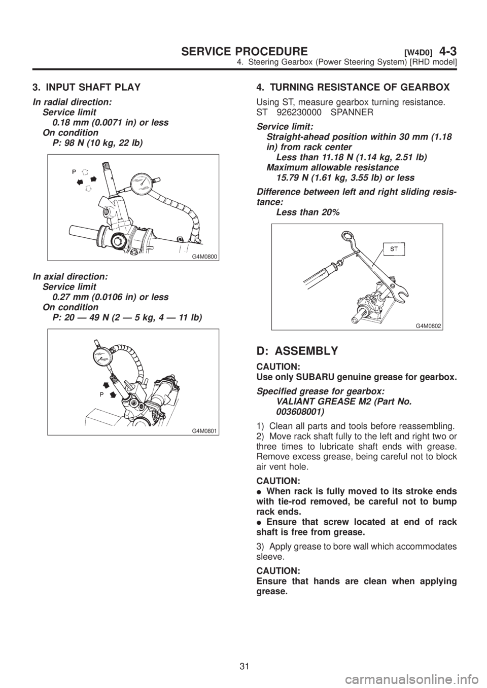
3. INPUT SHAFT PLAY
In radial direction:
Service limit
0.18 mm (0.0071 in) or less
On condition
P: 98 N (10 kg, 22 lb)
G4M0800
In axial direction:
Service limit
0.27 mm (0.0106 in) or less
On condition
P:20Ð49N(2Ð5kg,4Ð11lb)
G4M0801
4. TURNING RESISTANCE OF GEARBOX
Using ST, measure gearbox turning resistance.
ST 926230000 SPANNER
Service limit:
Straight-ahead position within 30 mm (1.18
in) from rack center
Less than 11.18 N (1.14 kg, 2.51 lb)
Maximum allowable resistance
15.79 N (1.61 kg, 3.55 lb) or less
Difference between left and right sliding resis-
tance:
Less than 20%
G4M0802
D: ASSEMBLY
CAUTION:
Use only SUBARU genuine grease for gearbox.
Specified grease for gearbox:
VALIANT GREASE M2 (Part No.
003608001)
1) Clean all parts and tools before reassembling.
2) Move rack shaft fully to the left and right two or
three times to lubricate shaft ends with grease.
Remove excess grease, being careful not to block
air vent hole.
CAUTION:
IWhen rack is fully moved to its stroke ends
with tie-rod removed, be careful not to bump
rack ends.
IEnsure that screw located at end of rack
shaft is free from grease.
3) Apply grease to bore wall which accommodates
sleeve.
CAUTION:
Ensure that hands are clean when applying
grease.
31
[W4D0]4-3SERVICE PROCEDURE
4. Steering Gearbox (Power Steering System) [RHD model]
Page 824 of 1456

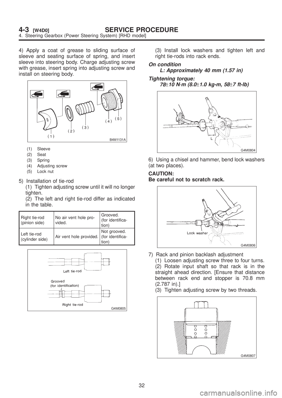
4) Apply a coat of grease to sliding surface of
sleeve and seating surface of spring, and insert
sleeve into steering body. Charge adjusting screw
with grease, insert spring into adjusting screw and
install on steering body.
B4M1131A
(1) Sleeve
(2) Seat
(3) Spring
(4) Adjusting screw
(5) Lock nut
5) Installation of tie-rod
(1) Tighten adjusting screw until it will no longer
tighten.
(2) The left and right tie-rod differ as indicated
in the table.
Right tie-rod
(pinion side)No air vent hole pro-
vided.Grooved.
(for identifica-
tion)
Left tie-rod
(cylinder side)Air vent hole provided.Not grooved.
(for identifica-
tion)
G4M0805
(3) Install lock washers and tighten left and
right tie-rods into rack ends.
On condition
L: Approximately 40 mm (1.57 in)
Tightening torque:
78
±10 N´m (8.0±1.0 kg-m, 58±7 ft-lb)
G4M0804
6) Using a chisel and hammer, bend lock washers
(at two places).
CAUTION:
Be careful not to scratch rack.
G4M0806
7) Rack and pinion backlash adjustment
(1) Loosen adjusting screw three to four turns.
(2) Rotate input shaft so that rack is in the
straight ahead direction. [Ensure that distance
between rack end and stopper is 70.8 mm
(2.787 in).]
(3) Tighten adjusting screw by two threads.
G4M0807
32
4-3[W4D0]SERVICE PROCEDURE
4. Steering Gearbox (Power Steering System) [RHD model]
Page 825 of 1456

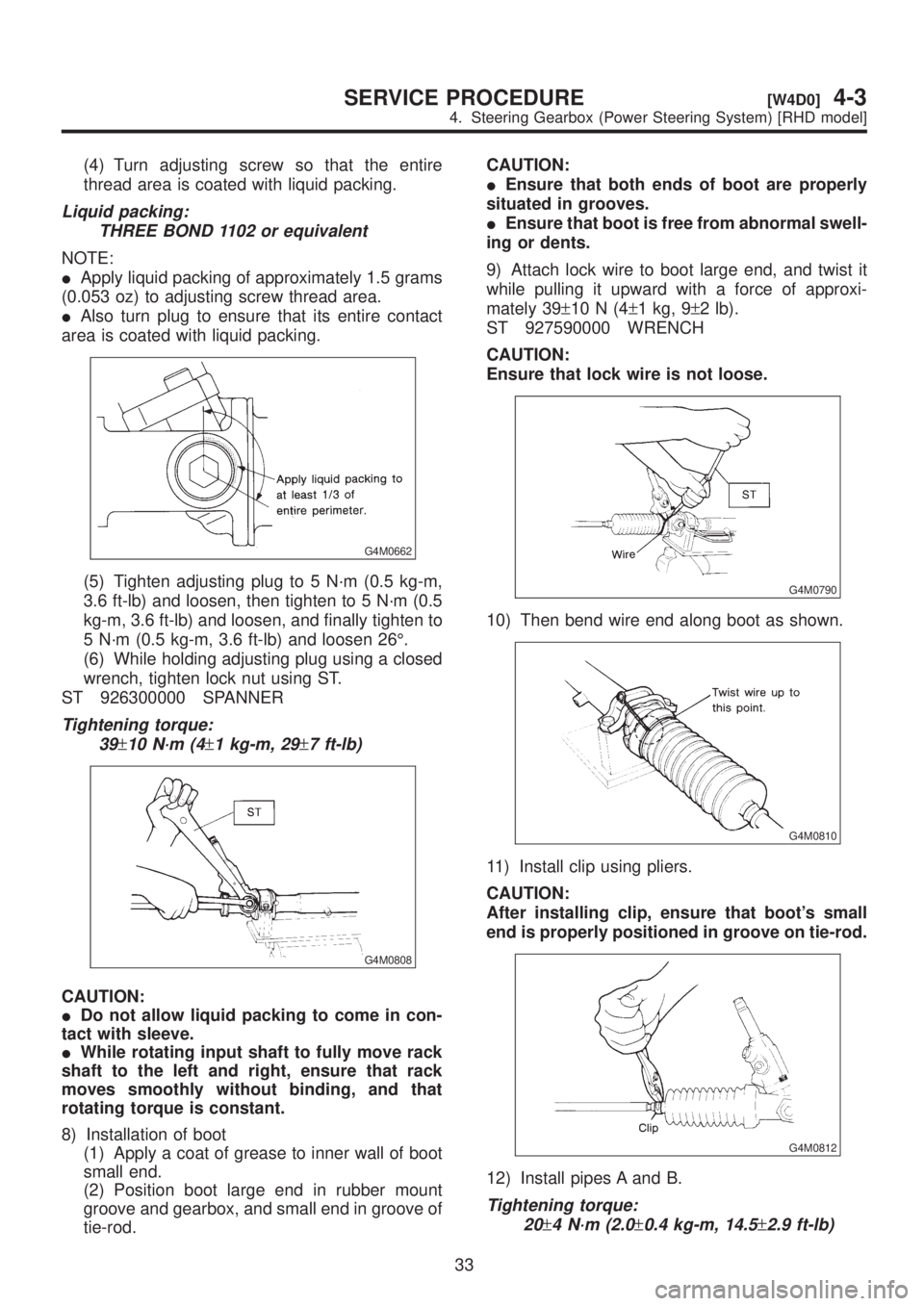
(4) Turn adjusting screw so that the entire
thread area is coated with liquid packing.
Liquid packing:
THREE BOND 1102 or equivalent
NOTE:
IApply liquid packing of approximately 1.5 grams
(0.053 oz) to adjusting screw thread area.
IAlso turn plug to ensure that its entire contact
area is coated with liquid packing.
G4M0662
(5) Tighten adjusting plug to 5 N´m (0.5 kg-m,
3.6 ft-lb) and loosen, then tighten to 5 N´m (0.5
kg-m, 3.6 ft-lb) and loosen, and finally tighten to
5 N´m (0.5 kg-m, 3.6 ft-lb) and loosen 26É.
(6) While holding adjusting plug using a closed
wrench, tighten lock nut using ST.
ST 926300000 SPANNER
Tightening torque:
39
±10 N´m (4±1 kg-m, 29±7 ft-lb)
G4M0808
CAUTION:
IDo not allow liquid packing to come in con-
tact with sleeve.
IWhile rotating input shaft to fully move rack
shaft to the left and right, ensure that rack
moves smoothly without binding, and that
rotating torque is constant.
8) Installation of boot
(1) Apply a coat of grease to inner wall of boot
small end.
(2) Position boot large end in rubber mount
groove and gearbox, and small end in groove of
tie-rod.CAUTION:
IEnsure that both ends of boot are properly
situated in grooves.
IEnsure that boot is free from abnormal swell-
ing or dents.
9) Attach lock wire to boot large end, and twist it
while pulling it upward with a force of approxi-
mately 39±10N(4±1 kg, 9±2 lb).
ST 927590000 WRENCH
CAUTION:
Ensure that lock wire is not loose.
G4M0790
10) Then bend wire end along boot as shown.
G4M0810
11) Install clip using pliers.
CAUTION:
After installing clip, ensure that boot's small
end is properly positioned in groove on tie-rod.
G4M0812
12) Install pipes A and B.
Tightening torque:
20
±4 N´m (2.0±0.4 kg-m, 14.5±2.9 ft-lb)
33
[W4D0]4-3SERVICE PROCEDURE
4. Steering Gearbox (Power Steering System) [RHD model]
Page 826 of 1456
E: INSTALLATION
Installation is in the reverse order of removal.
Do the following:
CAUTION:
When adjusting toe-in, hold boot as shown to
prevent it from being rotated or twisted. If
twisted, straighten it.
G4M0132
F: ADJUSTMENT
1) Adjust front toe.
Standard of front toe:
IN 3 Ð OUT 3 mm (IN 0.12 Ð OUT 0.12
in)
G4M0133
2) Adjust steering angle of wheels.
Standard of steering angle:
Inner wheel 37.6É
±1.5É
Outer wheel 32.6É
±1.5É
3) If steering wheel spokes are not horizontal
when wheels are set in the straight ahead position,
and error is more than 5É on the periphery of steer-
ing wheel, correctly re-install the steering wheel.
B4M0133A
4) If steering wheel spokes are not horizontal with
vehicle set in the straight ahead position after this
adjustment, correct it by turning the right and left
tie-rods in the same direction by the same amount.
G4M0135
34
4-3[W4E0]SERVICE PROCEDURE
4. Steering Gearbox (Power Steering System) [RHD model]