Page 1175 of 1456
9) Disconnect front sub sensor connector (A), side
airbag sensor connector (B) (side airbag equipped
model) and then remove protector (C).
10) Detach clips and then remove airbag main
harness.
B5M0516A
11) Installation is in the reverse order of removal.
13
[W4A0]5-5SERVICE PROCEDURE
4. Main Harness
Page 1178 of 1456

C: INSTALLATION
CAUTION:
Failure to do this might damage roll connector.
1) Before installing combination switch, check to
ensure that combination switch is off and front
wheels are set in the straight ahead position.
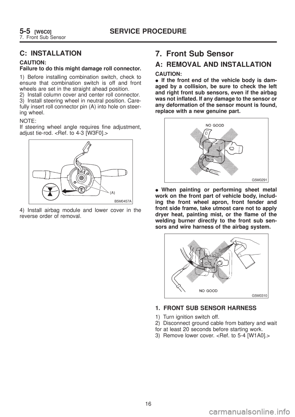
2) Install column cover and center roll connector.
3) Install steering wheel in neutral position. Care-
fully insert roll connector pin (A) into hole on steer-
ing wheel.
NOTE:
If steering wheel angle requires fine adjustment,
adjust tie-rod.
B5M0457A
4) Install airbag module and lower cover in the
reverse order of removal.
7. Front Sub Sensor
A: REMOVAL AND INSTALLATION
CAUTION:
IIf the front end of the vehicle body is dam-
aged by a collision, be sure to check the left
and right front sub sensors, even if the airbag
was not inflated. If any damage to the sensor or
any deformation of the sensor mount is found,
replace with a new genuine part.
G5M0291
IWhen painting or performing sheet metal
work on the front part of vehicle body, includ-
ing the front wheel apron, front fender and
front side frame, take utmost care not to apply
dryer heat, painting mist, or the flame of the
welding burner directly to the front sub sen-
sors and wire harness of the airbag system.
G5M0310
1. FRONT SUB SENSOR HARNESS
1) Turn ignition switch off.
2) Disconnect ground cable from battery and wait
for at least 20 seconds before starting work.
3) Remove lower cover.
16
5-5[W6C0]SERVICE PROCEDURE
7. Front Sub Sensor
Page 1179 of 1456

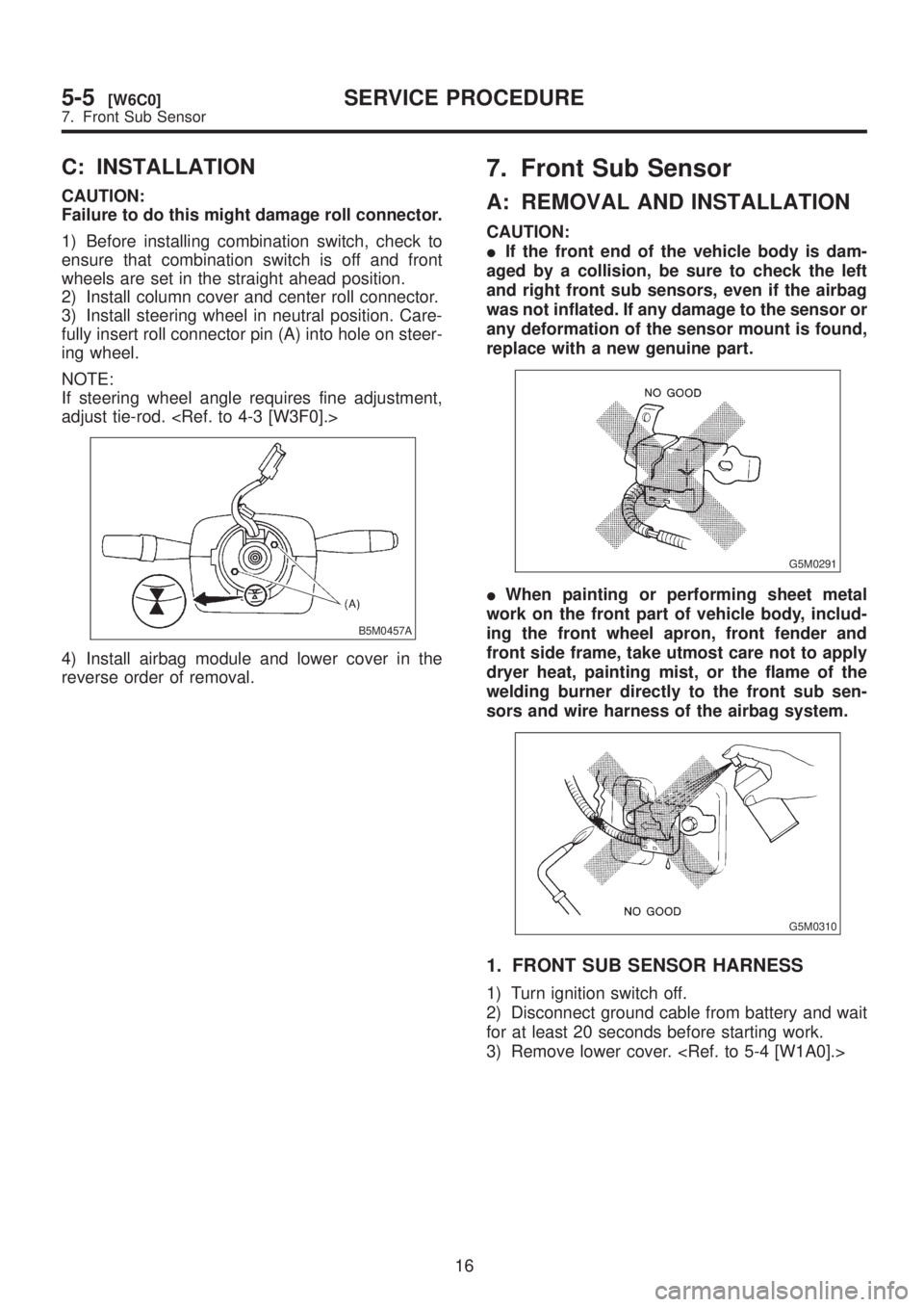
C: INSTALLATION
CAUTION:
Failure to do this might damage roll connector.
1) Before installing combination switch, check to
ensure that combination switch is off and front
wheels are set in the straight ahead position.
2) Install column cover and center roll connector.
3) Install steering wheel in neutral position. Care-
fully insert roll connector pin (A) into hole on steer-
ing wheel.
NOTE:
If steering wheel angle requires fine adjustment,
adjust tie-rod.
B5M0457A
4) Install airbag module and lower cover in the
reverse order of removal.
7. Front Sub Sensor
A: REMOVAL AND INSTALLATION
CAUTION:
IIf the front end of the vehicle body is dam-
aged by a collision, be sure to check the left
and right front sub sensors, even if the airbag
was not inflated. If any damage to the sensor or
any deformation of the sensor mount is found,
replace with a new genuine part.
G5M0291
IWhen painting or performing sheet metal
work on the front part of vehicle body, includ-
ing the front wheel apron, front fender and
front side frame, take utmost care not to apply
dryer heat, painting mist, or the flame of the
welding burner directly to the front sub sen-
sors and wire harness of the airbag system.
G5M0310
1. FRONT SUB SENSOR HARNESS
1) Turn ignition switch off.
2) Disconnect ground cable from battery and wait
for at least 20 seconds before starting work.
3) Remove lower cover.
16
5-5[W6C0]SERVICE PROCEDURE
7. Front Sub Sensor
Page 1180 of 1456
4) Disconnect airbag connector (AB3) and (AB8)
below steering column.
CAUTION:
Do not reconnect airbag connector at steering
column until front sub sensors are securely re-
installed.
G5M0312
5) Remove front side sill cover and then discon-
nect front sub sensor connector.
[M2F2].>
B5M0517
6) Remove front wheel and mud guard.
7) Disconnect connector from front sub sensor
assembly.
B5M0518
8) Remove wiring harness clips.
G5M0315
9) Remove grommet and then detach front sub
sensor harness.
G5M0316
2. FRONT SUB SENSOR ASSEMBLY
1) Turn ignition switch off.
2) Disconnect ground cable from battery and wait
for at least 20 seconds before starting work.
3) Remove front wheel and mud guard.
4) Disconnect connector from front sub sensor
assembly.
B5M0518
17
[W7A2]5-5SERVICE PROCEDURE
7. Front Sub Sensor
Page 1181 of 1456

5) Remove front sub sensor.
B5M0519
6) Installation is in the reverse order of removal.
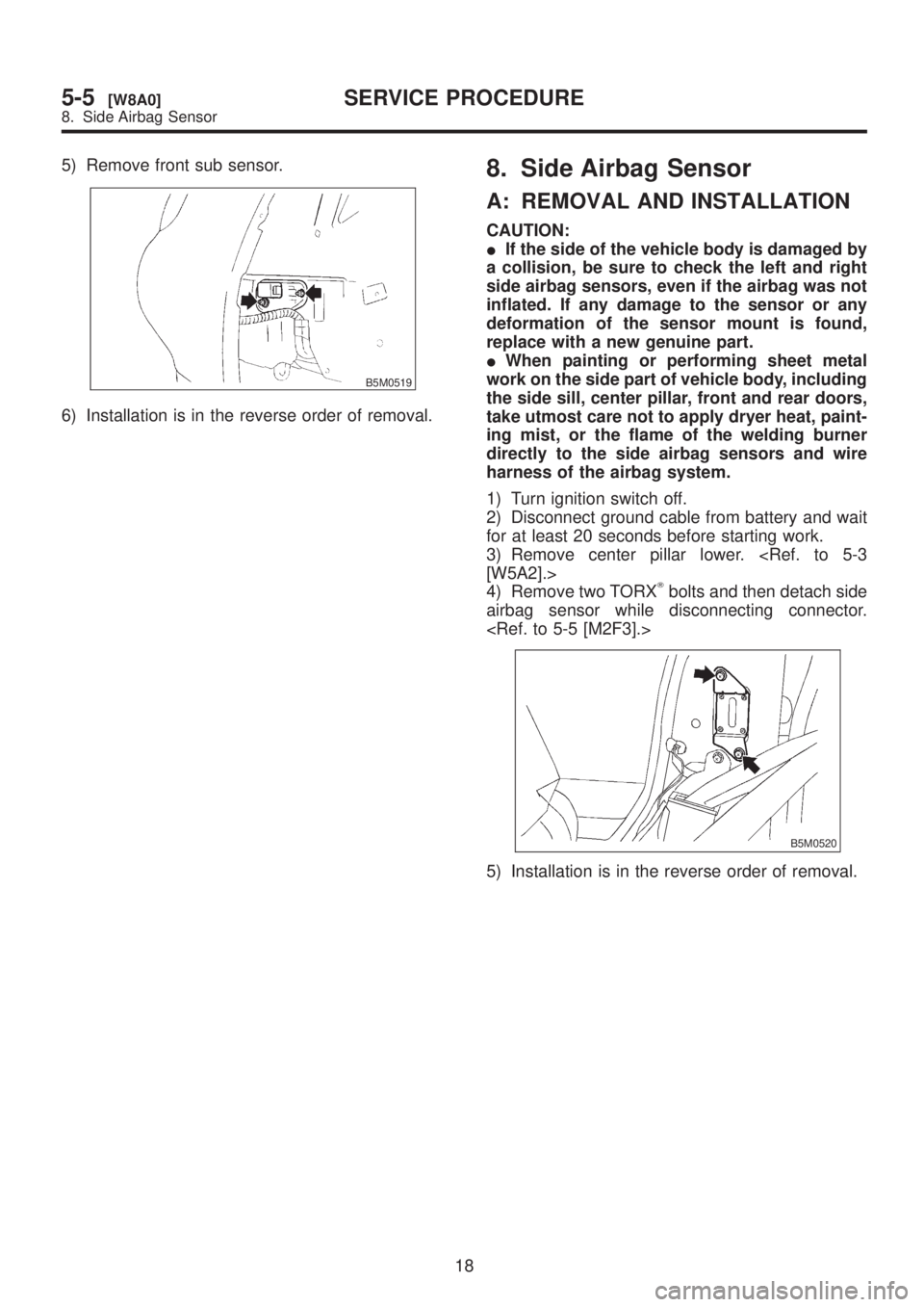
8. Side Airbag Sensor
A: REMOVAL AND INSTALLATION
CAUTION:
IIf the side of the vehicle body is damaged by
a collision, be sure to check the left and right
side airbag sensors, even if the airbag was not
inflated. If any damage to the sensor or any
deformation of the sensor mount is found,
replace with a new genuine part.
IWhen painting or performing sheet metal
work on the side part of vehicle body, including
the side sill, center pillar, front and rear doors,
take utmost care not to apply dryer heat, paint-
ing mist, or the flame of the welding burner
directly to the side airbag sensors and wire
harness of the airbag system.
1) Turn ignition switch off.
2) Disconnect ground cable from battery and wait
for at least 20 seconds before starting work.
3) Remove center pillar lower.
[W5A2].>
4) Remove two TORX
Tbolts and then detach side
airbag sensor while disconnecting connector.
B5M0520
5) Installation is in the reverse order of removal.
18
5-5[W8A0]SERVICE PROCEDURE
8. Side Airbag Sensor
Page 1182 of 1456

5) Remove front sub sensor.
B5M0519
6) Installation is in the reverse order of removal.
8. Side Airbag Sensor
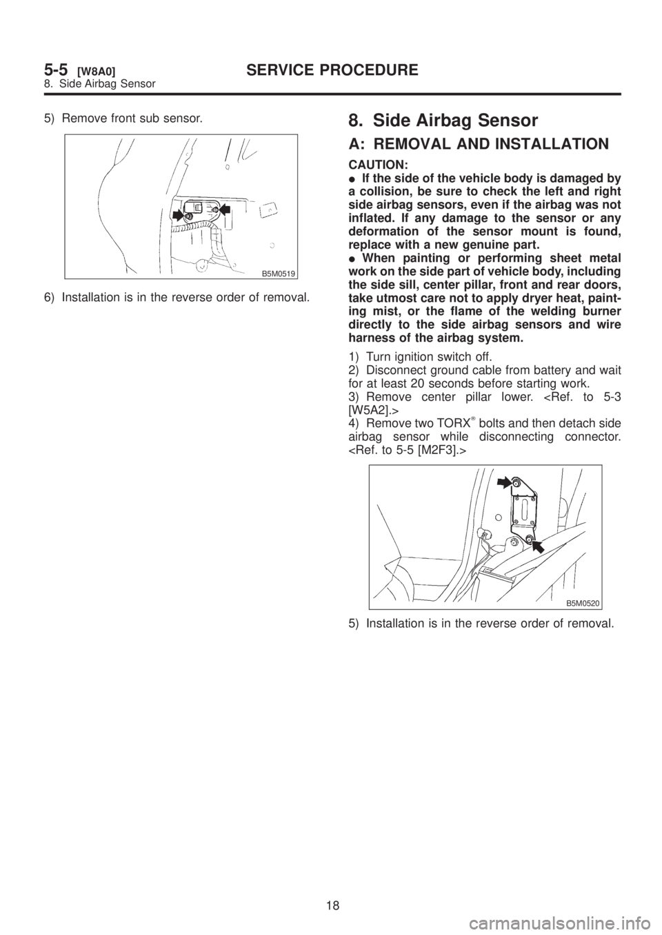
A: REMOVAL AND INSTALLATION
CAUTION:
IIf the side of the vehicle body is damaged by
a collision, be sure to check the left and right
side airbag sensors, even if the airbag was not
inflated. If any damage to the sensor or any
deformation of the sensor mount is found,
replace with a new genuine part.
IWhen painting or performing sheet metal
work on the side part of vehicle body, including
the side sill, center pillar, front and rear doors,
take utmost care not to apply dryer heat, paint-
ing mist, or the flame of the welding burner
directly to the side airbag sensors and wire
harness of the airbag system.
1) Turn ignition switch off.
2) Disconnect ground cable from battery and wait
for at least 20 seconds before starting work.
3) Remove center pillar lower.
[W5A2].>
4) Remove two TORX
Tbolts and then detach side
airbag sensor while disconnecting connector.
B5M0520
5) Installation is in the reverse order of removal.
18
5-5[W8A0]SERVICE PROCEDURE
8. Side Airbag Sensor
Page 1203 of 1456
(3) Remove air intake duct (A) and (B) as a
unit.
B2M2012
(4) Remove resonator chamber.
B2M2306
3) Remove air cleaner upper case and air cleaner
element. (Except California SPEC. vehicle)
(1) Disconnect mass air flow sensor connector.
B2M2018
(2) Remove two clips securing air cleaner
upper cover.
(3) Loosen the clamp screw and separate air
cleaner upper cover from air intake duct.
(4) Remove air cleaner element.
B2M2290
4) Remove #1 spark plug cord by pulling boot, not
cord itself.
B6M0922A
5) Remove spark plug with the spark plug socket.
B6M0923
6) Installation is in the reverse order of removal.
Tightening torque (Spark plug):
20.6
±2.9 N´m (2.10±0.30 kg-m, 15.19±2.14
ft-lb)
21
[W3A1]6-1SERVICE PROCEDURE
3. Spark Plug
Page 1205 of 1456
(3) Remove air intake duct (A) and (B) as a
unit.
B2M2012
(4) Remove resonator chamber.
B2M2306
3) Remove air cleaner upper case and air cleaner
element. (Except California SPEC. vehicle)
(1) Disconnect mass air flow sensor connector.
B2M2018
(2) Remove two clips securing air cleaner
upper cover.
(3) Loosen the clamp screw and separate air
cleaner upper cover from air intake duct.
(4) Remove air cleaner element.
B2M2290
4) Remove #3 spark plug cord by pulling boot, not
cord itself.
B6M0928A
5) Remove spark plug with the spark plug socket.
B6M0925
6) Installation is in the reverse order of removal.
Tightening torque (Spark plug):
20.6
±2.9 N´m (2.10±0.30 kg-m, 15.19±2.14
ft-lb)
23
[W3A3]6-1SERVICE PROCEDURE
3. Spark Plug