1999 SUBARU LEGACY sensor
[x] Cancel search: sensorPage 1208 of 1456
Tightening torque (Spark plug):
20.6
±2.9 N´m (2.10±0.30 kg-m, 15.19±2.14
ft-lb)
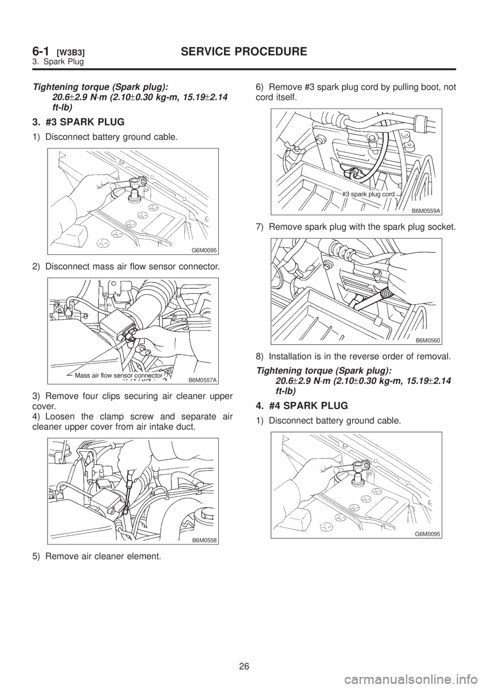
3. #3 SPARK PLUG
1) Disconnect battery ground cable.
G6M0095
2) Disconnect mass air flow sensor connector.
B6M0557A
3) Remove four clips securing air cleaner upper
cover.
4) Loosen the clamp screw and separate air
cleaner upper cover from air intake duct.
B6M0558
5) Remove air cleaner element.6) Remove #3 spark plug cord by pulling boot, not
cord itself.
B6M0559A
7) Remove spark plug with the spark plug socket.
B6M0560
8) Installation is in the reverse order of removal.
Tightening torque (Spark plug):
20.6
±2.9 N´m (2.10±0.30 kg-m, 15.19±2.14
ft-lb)
4. #4 SPARK PLUG
1) Disconnect battery ground cable.
G6M0095
26
6-1[W3B3]SERVICE PROCEDURE
3. Spark Plug
Page 1210 of 1456
C: REMOVAL (2500 cc OUTBACK
MODEL)
CAUTION:
All spark plugs installed on an engine, must be
of the same heat range.
Spark plug:
NGK: PFR5B-11
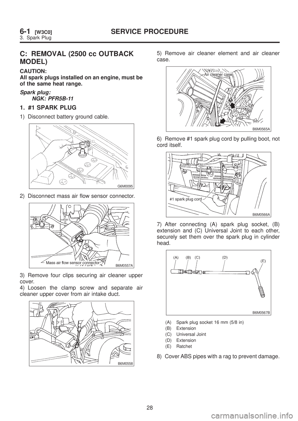
1. #1 SPARK PLUG
1) Disconnect battery ground cable.
G6M0095
2) Disconnect mass air flow sensor connector.
B6M0557A
3) Remove four clips securing air cleaner upper
cover.
4) Loosen the clamp screw and separate air
cleaner upper cover from air intake duct.
B6M0558
5) Remove air cleaner element and air cleaner
case.
B6M0565A
6) Remove #1 spark plug cord by pulling boot, not
cord itself.
B6M0566A
7) After connecting (A) spark plug socket, (B)
extension and (C) Universal Joint to each other,
securely set them over the spark plug in cylinder
head.
B6M0567B
(A) Spark plug socket 16 mm (5/8 in)
(B) Extension
(C) Universal Joint
(D) Extension
(E) Ratchet
8) Cover ABS pipes with a rag to prevent damage.
28
6-1[W3C0]SERVICE PROCEDURE
3. Spark Plug
Page 1212 of 1456
CAUTION:
When removing spark plug, cover the ATF cool-
ing pipes with a rag to prevent damage.
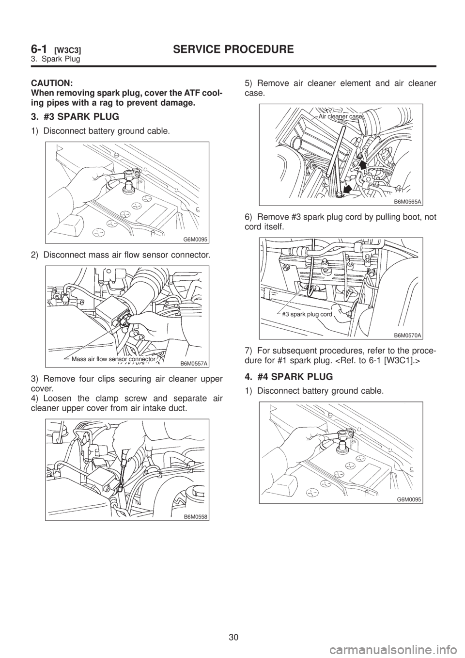
3. #3 SPARK PLUG
1) Disconnect battery ground cable.
G6M0095
2) Disconnect mass air flow sensor connector.
B6M0557A
3) Remove four clips securing air cleaner upper
cover.
4) Loosen the clamp screw and separate air
cleaner upper cover from air intake duct.
B6M0558
5) Remove air cleaner element and air cleaner
case.
B6M0565A
6) Remove #3 spark plug cord by pulling boot, not
cord itself.
B6M0570A
7) For subsequent procedures, refer to the proce-
dure for #1 spark plug.
4. #4 SPARK PLUG
1) Disconnect battery ground cable.
G6M0095
30
6-1[W3C3]SERVICE PROCEDURE
3. Spark Plug
Page 1257 of 1456
15. Vehicle Speed Sensor 2
A: GENERAL PRECAUTIONS
(1) Be careful not to drop or bump sensor as this
may break built-in magnet.
(2) Drive key is designed to separate from vehicle
speed sensor 2. Be careful not to lose it or forget
to install.
(3) Vehicle speed sensor 2 is installed in part
(which contains bearings, etc., finished to a high
degree of accuracy). Do not allow foreign matter
(filings, sand, etc.) to get into it.
(4) When checking output of vehicle speed sensor
2 as a single unit, ensure test leads are connected
to their correct terminals. Failure to do this may
damage internal IC.
(5) Discard vehicle speed sensor 2 after removal;
replace with new one.
B: REMOVAL
CAUTION:
IBe careful when removing vehicle speed
sensor 2 immediately after driving vehicle for a
while, as temperature around it is high.
IBefore removing vehicle speed sensor 2,
clean dirt, etc. from surrounding areas. Take
care not to allow foreign matter to get into
mounting hole.
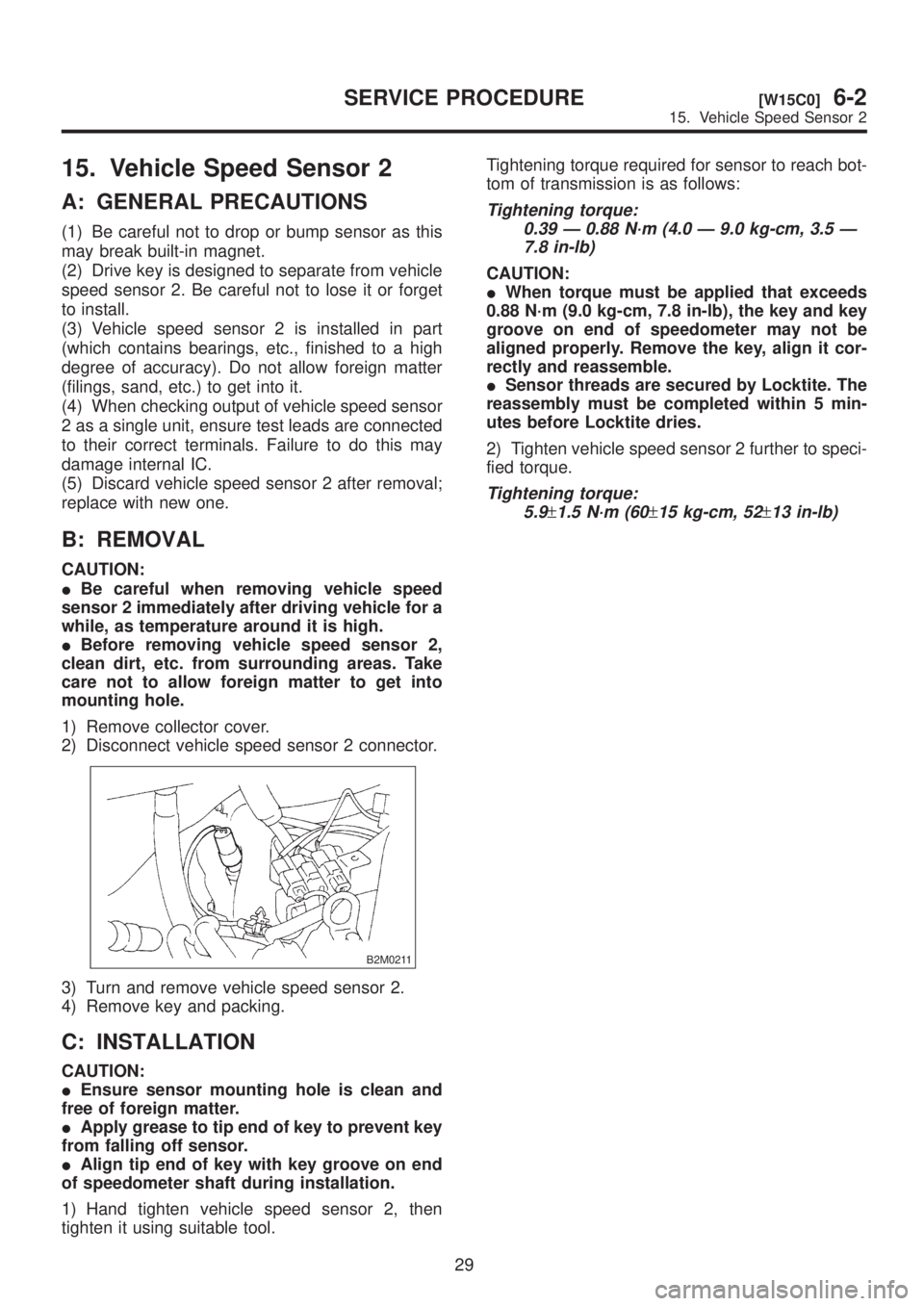
1) Remove collector cover.
2) Disconnect vehicle speed sensor 2 connector.
B2M0211
3) Turn and remove vehicle speed sensor 2.
4) Remove key and packing.
C: INSTALLATION
CAUTION:
IEnsure sensor mounting hole is clean and
free of foreign matter.
IApply grease to tip end of key to prevent key
from falling off sensor.
IAlign tip end of key with key groove on end
of speedometer shaft during installation.
1) Hand tighten vehicle speed sensor 2, then
tighten it using suitable tool.Tightening torque required for sensor to reach bot-
tom of transmission is as follows:
Tightening torque:
0.39 Ð 0.88 N´m (4.0 Ð 9.0 kg-cm, 3.5 Ð
7.8 in-lb)
CAUTION:
IWhen torque must be applied that exceeds
0.88 N´m (9.0 kg-cm, 7.8 in-lb), the key and key
groove on end of speedometer may not be
aligned properly. Remove the key, align it cor-
rectly and reassemble.
ISensor threads are secured by Locktite. The
reassembly must be completed within 5 min-
utes before Locktite dries.
2) Tighten vehicle speed sensor 2 further to speci-
fied torque.
Tightening torque:
5.9
±1.5 N´m (60±15 kg-cm, 52±13 in-lb)
29
[W15C0]6-2SERVICE PROCEDURE
15. Vehicle Speed Sensor 2
Page 1274 of 1456
4) Turn ignition switch OFF with main switch ON
(which is indicated by illumination.).
5) Turn ignition switch ON again to ensure that
indicator light remains OFF.
2. COMMAND SWITCH
1) Check that command switch is properly set in
ªSET/COASTº, ªRESUME/ACCELº or ªCANCELº
mode.
2) Also check that command switch returns to the
original position when released.
3. CONSTANT SPEED TEST
1) Turn main switch ON.
2) Drive vehicle at speed greater than 40 km/h (25
MPH).
3) Press command switch to set in ªSET/COASTº
mode.
4) Ensure that vehicle is maintained at the speed
set when command switch was pressed.
4. ACCELERATION TEST
1) Set vehicle speed at speed greater than 40
km/h (25 MPH).
2) Ensure that vehicle continues to accelerate
while holding command switch in RESUME/
ACCEL mode, and that vehicle maintains that
optional speed when command switch is released.
5. DECELERATION TEST
1) Set vehicle speed at optional speed greater
than 40 km/h (25 MPH).
2) Ensure that vehicle continues to decelerate
while holding command switch in SET/COAST
mode, and that it maintains that optional speed
when command switch is released.
NOTE:
When vehicle speed reaches the lower speed limit
of 30 km/h (19 MPH) during deceleration, cruise
control will be released.
23. Security System
A: REMOVAL AND INSTALLATION
1. SECURITY CONTROL MODULE
1) Disconnect battery ground cable.
2) Remove radio.
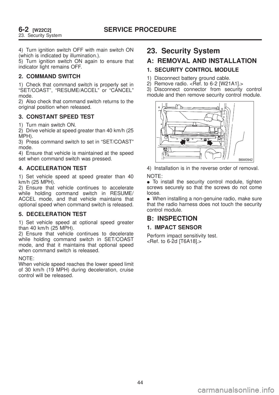
3) Disconnect connector from security control
module and then remove security control module.
B6M0942
4) Installation is in the reverse order of removal.
NOTE:
ITo install the security control module, tighten
screws securely so that the screws do not come
loose.
IWhen installing a non-genuine radio, make sure
that the radio harness does not touch the security
control module.
B: INSPECTION
1. IMPACT SENSOR
Perform impact sensitivity test.
44
6-2[W22C2]SERVICE PROCEDURE
23. Security System
Page 1275 of 1456
4) Turn ignition switch OFF with main switch ON
(which is indicated by illumination.).
5) Turn ignition switch ON again to ensure that
indicator light remains OFF.
2. COMMAND SWITCH
1) Check that command switch is properly set in
ªSET/COASTº, ªRESUME/ACCELº or ªCANCELº
mode.
2) Also check that command switch returns to the
original position when released.
3. CONSTANT SPEED TEST
1) Turn main switch ON.
2) Drive vehicle at speed greater than 40 km/h (25
MPH).
3) Press command switch to set in ªSET/COASTº
mode.
4) Ensure that vehicle is maintained at the speed
set when command switch was pressed.
4. ACCELERATION TEST
1) Set vehicle speed at speed greater than 40
km/h (25 MPH).
2) Ensure that vehicle continues to accelerate
while holding command switch in RESUME/
ACCEL mode, and that vehicle maintains that
optional speed when command switch is released.
5. DECELERATION TEST
1) Set vehicle speed at optional speed greater
than 40 km/h (25 MPH).
2) Ensure that vehicle continues to decelerate
while holding command switch in SET/COAST
mode, and that it maintains that optional speed
when command switch is released.
NOTE:
When vehicle speed reaches the lower speed limit
of 30 km/h (19 MPH) during deceleration, cruise
control will be released.
23. Security System
A: REMOVAL AND INSTALLATION
1. SECURITY CONTROL MODULE
1) Disconnect battery ground cable.
2) Remove radio.
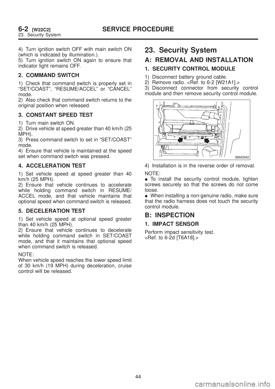
3) Disconnect connector from security control
module and then remove security control module.
B6M0942
4) Installation is in the reverse order of removal.
NOTE:
ITo install the security control module, tighten
screws securely so that the screws do not come
loose.
IWhen installing a non-genuine radio, make sure
that the radio harness does not touch the security
control module.
B: INSPECTION
1. IMPACT SENSOR
Perform impact sensitivity test.
44
6-2[W22C2]SERVICE PROCEDURE
23. Security System
Page 1289 of 1456

5) Some connectors are provided with a lock. One
type of such a connector is disconnected by push-
ing the lock, and the other, by moving the lock up.
In either type the lock shape must be identified
before attempting to disconnect the connector.
To connect, insert the connector until it snaps and
confirm that it is tightly connected.
G6M0213
6) When checking continuity between connector
terminals, or measuring voltage across the termi-
nal and ground, always contact tester probe(s) on
terminals from the wiring connection side. If the
probe is too thick to gain access to the terminal,
use ªminiº test leads.
To check water-proof connectors (which are not
accessible from the wiring side), contact test
probes on the terminal side being careful not to
bend or damage the terminals.
G6M0214
7) Sensors, relays, electrical unit, etc., are sensi-
tive to strong impacts.
Handle them with care so that they are not dropped
or mishandled.
9
[D3B0]6-3WIRING DIAGRAM
3. Working Precautions
Page 1296 of 1456
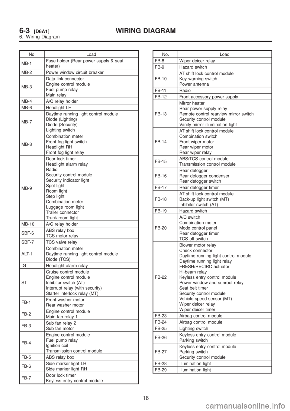
No. Load
MB-1Fuse holder (Rear power supply & seat
heater)
MB-2 Power window circuit breaker
MB-3Data link connector
Engine control module
Fuel pump relay
Main relay
MB-4 A/C relay holder
MB-6 Headlight LH
MB-7Daytime running light control module
Diode (Lighting)
Diode (Security)
Lighting switch
MB-8Combination meter
Front fog light switch
Headlight RH
Front fog light relay
MB-9Door lock timer
Headlight alarm relay
Radio
Security control module
Security indicator light
Spot light
Room light
Step light
Combination meter
Luggage room light
Trailer connector
Trunk room light
MB-10 A/C relay holder
SBF-6ABS relay box
TCS motor relay
SBF-7 TCS valve relay
ALT-1Combination meter
Daytime running light control module
Diode (TCS)
IG Headlight alarm relay
STCruise control module
Engine control module
Inhibitor switch (AT)
Interrupt relay (with security)
Starter interlock relay (MT)
FB-1Front washer motor
Rear washer motor
FB-2Engine control module
Main fan relay 1
FB-3Sub fan relay 2
Sub fan motor
FB-4Engine control module
Fuel pump relay
Ignition coil
Transmission control module
FB-5 ABS relay box
FB-6Side marker light LH
Side marker light RH
FB-7Door lock timer
Keyless entry control moduleNo. Load
FB-8 Wiper deicer relay
FB-9 Hazard switch
FB-10AT shift lock control module
Key warning switch
Power antenna
FB-11 Radio
FB-12 Front accessory power supply
FB-13Mirror heater
Rear power supply relay
Remote control rearview mirror switch
Security control module
Vanity mirror illumination light
FB-14AT shift lock control module
Combination switch
Front wiper motor
Rear wiper motor
Rear wiper relay
FB-15ABS/TCS control module
Transmission control module
FB-16Rear defogger
Rear defogger condenser
Rear defogger switch
FB-17 Rear defogger timer
FB-18AT shift lock control module
Back-up light switch (MT)
Inhibitor switch (AT)
FB-19 Hazard switch
FB-20A/C switch
Combination meter
Mode control panel
Rear defogger timer
TCS off switch
FB-22Blower motor relay
Check connector
Daytime running light control module
Daytime running light relay
FRESH/RECIRC actuator
Hi-beam relay
Keyless entry control module
Power window and sunroof relay
Seat belt timer
Security control module
Vehicle speed sensor (MT)
Wiper deicer relay
Wiper deicer timer
FB-23 Airbag control module
FB-24 Airbag control module
FB-25 Lighting switch
FB-26Keyless entry control module
Parking switch
FB-27Keyless entry control module
Parking switch
Security control module
FB-28 Illumination light
FB-29 Illumination light
16
6-3[D6A1]WIRING DIAGRAM
6. Wiring Diagram