Page 940 of 1456

C: INSPECTION WITH SELECT
MONITOR
16C1 : CHECK G SENSOR.
1) Turn ignition switch to OFF.
2) Connect select monitor connector to data link
connector.
3) Turn select monitor into {ABS/TCS} mode.
4) Set the display in the {Current Data Display &
Save} mode.
5) Read the G sensor output voltage.
:Is the indicated reading 2.3±0.2 V
when the vehicle is in horizontal
position?
: Go to step16C2.
: Replace G sensor.
16C2 : CHECK G SENSOR.
1) Remove console box.
2) Remove G sensor from vehicle. (Do not discon-
nect connector.)
3) Read the select monitor display.
B4M0917A
:Is the indicated reading 3.9±0.2 V
when G sensor is inclined forwards
to 90É?
: Go to step16C3.
: Replace G sensor.16C3 : CHECK G SENSOR.
Read the select monitor display.
B4M0918A
:Is the indicated reading 0.7±0.2 V
when G sensor is inclined backwards
to 90É?
: G sensor is normal.
: Replace G sensor.
D: INSTALLATION
1. FRONT ABS SENSOR
1) Install tone wheel on hub, then install housing
on hub assembly.
2) Temporarily install front ABS sensor on hous-
ing.
CAUTION:
Be careful not to strike ABS sensor's pole
piece and tone wheel's teeth against adjacent
metal parts during installation.
B4M1183A
3) Install front drive shaft to hub spline.
4-2 [W1E0].>
62
4-4[W16C1]SERVICE PROCEDURE
16. G Sensor
Page 941 of 1456

4) Install front ABS sensor on strut and wheel
apron bracket.
Tightening torque:
32
±10 N´m (3.3±1.0 kg-m, 24±7 ft-lb)
B4M1442A
5) Place a thickness gauge between ABS sensor's
pole piece and tone wheel's tooth face. After stan-
dard clearance is obtained over the entire
perimeter, tighten ABS sensor on housing to speci-
fied torque.
ABS sensor standard clearance:
0.9 Ð 1.4 mm (0.035 Ð 0.055 in)
Tightening torque:
32
±10 N´m (3.3±1.0 kg-m, 24±7 ft-lb)
CAUTION:
Check the marks on the harness to make sure
that no distortion exists. (RH: white, LH: yel-
low)
NOTE:
If the clearance is outside specifications, readjust.
17. Brake Pipe
A: SUPPLEMENTAL RESTRAINT
SYSTEM ªAIRBAGº
Airbag system wiring harness is routed near the
center brake pipe.
CAUTION:
IAll Airbag system wiring harness and con-
nectors are colored yellow. Do not use electri-
cal test equipment on these circuit.
IBe careful not to damage Airbag system wir-
ing harness when servicing the center brake
pipe.
B: REMOVAL AND INSTALLATION
CAUTION:
IWhen removing and installing the brake
pipe, make sure that it is not bent.
IAfter installing the brake pipe and hose,
bleed the air.
IAfter installing the brake hose, make sure
that it does not touch the tire or suspension
assembly, etc.
Brake pipe tightening torque:
15+3/þ2N´m (1.5+0.3/þ0.2kg-m, 10.8+2.2/þ1.4ft-lb)
63
[W17B0]4-4SERVICE PROCEDURE
17. Brake Pipe
Page 942 of 1456

4) Install front ABS sensor on strut and wheel
apron bracket.
Tightening torque:
32
±10 N´m (3.3±1.0 kg-m, 24±7 ft-lb)
B4M1442A
5) Place a thickness gauge between ABS sensor's
pole piece and tone wheel's tooth face. After stan-
dard clearance is obtained over the entire
perimeter, tighten ABS sensor on housing to speci-
fied torque.
ABS sensor standard clearance:
0.9 Ð 1.4 mm (0.035 Ð 0.055 in)
Tightening torque:
32
±10 N´m (3.3±1.0 kg-m, 24±7 ft-lb)
CAUTION:
Check the marks on the harness to make sure
that no distortion exists. (RH: white, LH: yel-
low)
NOTE:
If the clearance is outside specifications, readjust.
17. Brake Pipe
A: SUPPLEMENTAL RESTRAINT
SYSTEM ªAIRBAGº
Airbag system wiring harness is routed near the
center brake pipe.
CAUTION:
IAll Airbag system wiring harness and con-
nectors are colored yellow. Do not use electri-
cal test equipment on these circuit.
IBe careful not to damage Airbag system wir-
ing harness when servicing the center brake
pipe.
B: REMOVAL AND INSTALLATION
CAUTION:
IWhen removing and installing the brake
pipe, make sure that it is not bent.
IAfter installing the brake pipe and hose,
bleed the air.
IAfter installing the brake hose, make sure
that it does not touch the tire or suspension
assembly, etc.
Brake pipe tightening torque:
15+3/þ2N´m (1.5+0.3/þ0.2kg-m, 10.8+2.2/þ1.4ft-lb)
63
[W17B0]4-4SERVICE PROCEDURE
17. Brake Pipe
Page 1152 of 1456

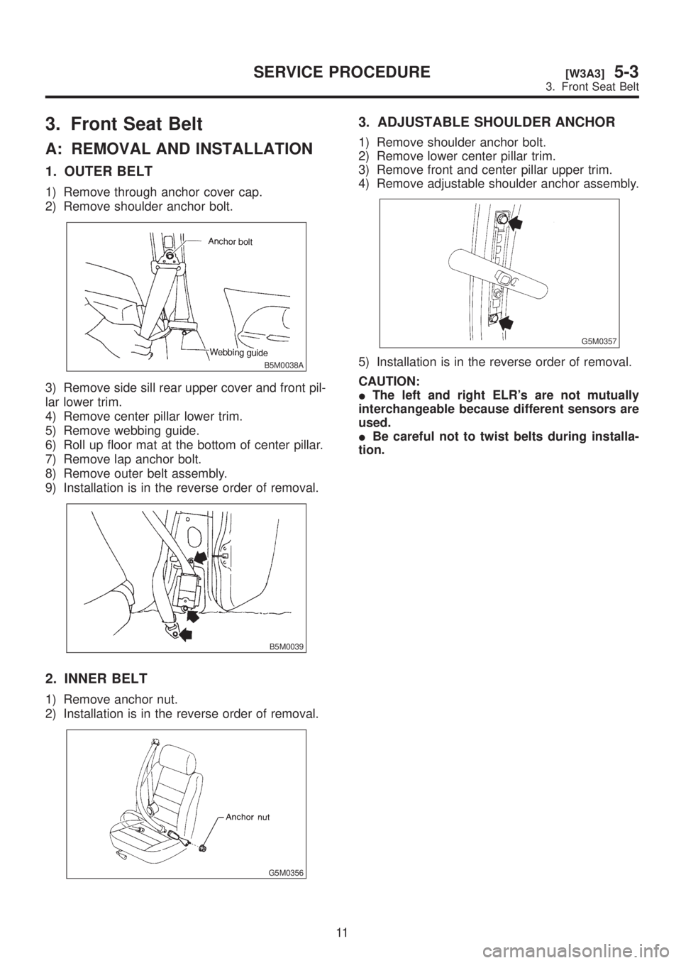
3. Front Seat Belt
A: REMOVAL AND INSTALLATION
1. OUTER BELT
1) Remove through anchor cover cap.
2) Remove shoulder anchor bolt.
B5M0038A
3) Remove side sill rear upper cover and front pil-
lar lower trim.
4) Remove center pillar lower trim.
5) Remove webbing guide.
6) Roll up floor mat at the bottom of center pillar.
7) Remove lap anchor bolt.
8) Remove outer belt assembly.
9) Installation is in the reverse order of removal.
B5M0039
2. INNER BELT
1) Remove anchor nut.
2) Installation is in the reverse order of removal.
G5M0356
3. ADJUSTABLE SHOULDER ANCHOR
1) Remove shoulder anchor bolt.
2) Remove lower center pillar trim.
3) Remove front and center pillar upper trim.
4) Remove adjustable shoulder anchor assembly.
G5M0357
5) Installation is in the reverse order of removal.
CAUTION:
IThe left and right ELR's are not mutually
interchangeable because different sensors are
used.
IBe careful not to twist belts during installa-
tion.
11
[W3A3]5-3SERVICE PROCEDURE
3. Front Seat Belt
Page 1156 of 1456

CAUTION:
IThe left and right ELR's are not mutually
interchangeable because different sensors are
used.
IBe careful not to twist belts during installa-
tion.
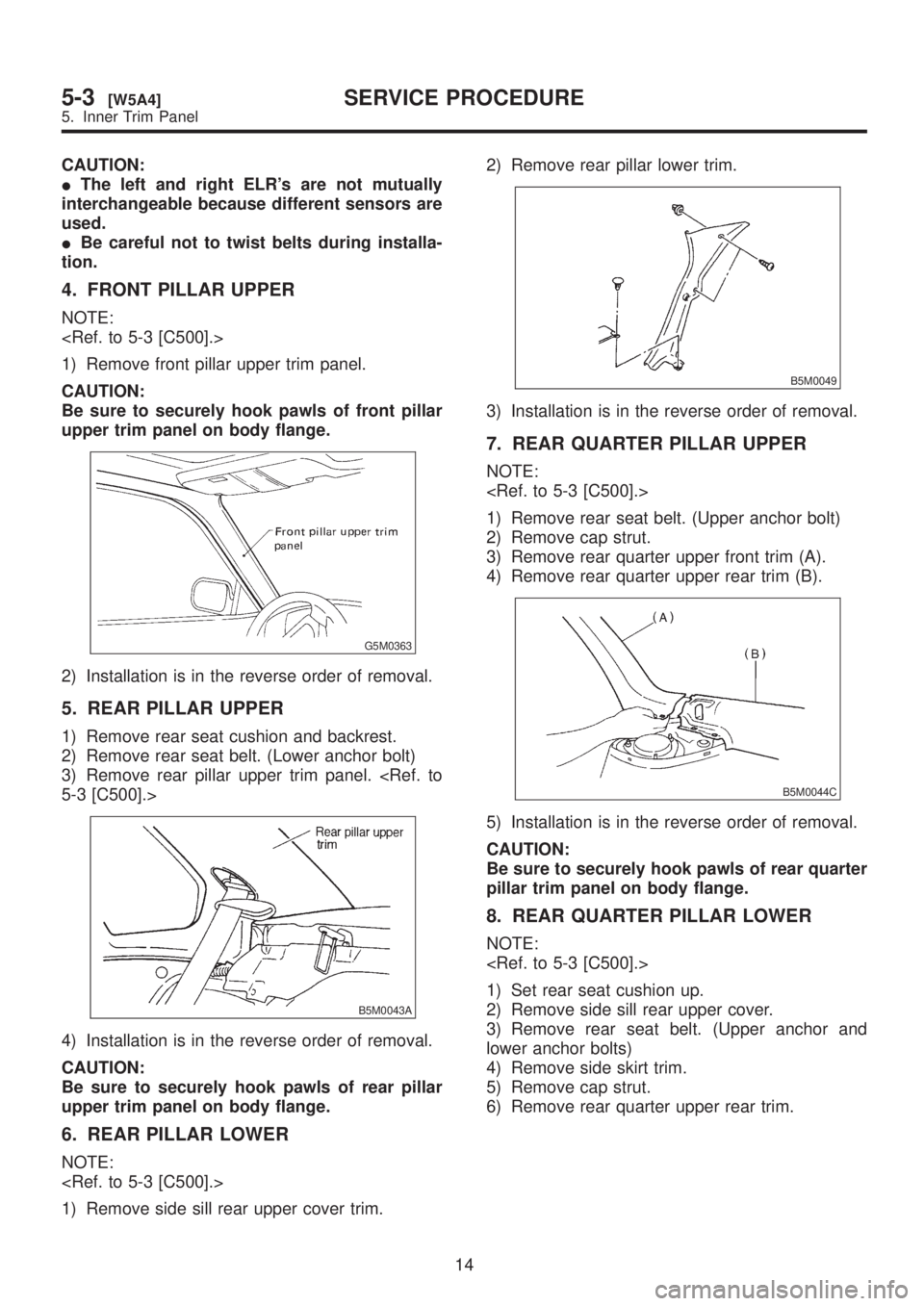
4. FRONT PILLAR UPPER
NOTE:
1) Remove front pillar upper trim panel.
CAUTION:
Be sure to securely hook pawls of front pillar
upper trim panel on body flange.
G5M0363
2) Installation is in the reverse order of removal.
5. REAR PILLAR UPPER
1) Remove rear seat cushion and backrest.
2) Remove rear seat belt. (Lower anchor bolt)
3) Remove rear pillar upper trim panel.
5-3 [C500].>
B5M0043A
4) Installation is in the reverse order of removal.
CAUTION:
Be sure to securely hook pawls of rear pillar
upper trim panel on body flange.
6. REAR PILLAR LOWER
NOTE:
1) Remove side sill rear upper cover trim.2) Remove rear pillar lower trim.
B5M0049
3) Installation is in the reverse order of removal.
7. REAR QUARTER PILLAR UPPER
NOTE:
1) Remove rear seat belt. (Upper anchor bolt)
2) Remove cap strut.
3) Remove rear quarter upper front trim (A).
4) Remove rear quarter upper rear trim (B).
B5M0044C
5) Installation is in the reverse order of removal.
CAUTION:
Be sure to securely hook pawls of rear quarter
pillar trim panel on body flange.
8. REAR QUARTER PILLAR LOWER
NOTE:
1) Set rear seat cushion up.
2) Remove side sill rear upper cover.
3) Remove rear seat belt. (Upper anchor and
lower anchor bolts)
4) Remove side skirt trim.
5) Remove cap strut.
6) Remove rear quarter upper rear trim.
14
5-3[W5A4]SERVICE PROCEDURE
5. Inner Trim Panel
Page 1165 of 1456
(1) Combination switch ASSY with
roll connector
(2) Airbag module ASSY (Driver)
(3) Airbag module ASSY (Passen-
ger)
(4) BRKT SD A
(5) BRKT P AB (LH)
(6) BRKT B
(7) BRKT P AB (RH)
(8) Side airbag sensor (RH)
(9) Side airbag sensor (LH)(10) Airbag module ASSY (Side)
(11) Extension harness
(12) Protector RH
(13) Airbag main harness
(14) Protector LH
(15) Front sub sensor (LH)
(16) Airbag control module
(17) Front sub sensor (RH)
(18) Front sub sensor harness (LH)
(19) Front sub sensor harness (RH)
(20) Side airbag harness (LH)(21) Side airbag harness (RH)
Tightening torque: N´m (kg-m, ft-lb)
T1:
1.8±0.5 (0.18±0.05, 1.3±0.4)
T2:4.4±1.5 (0.45±0.15, 3.3±1.1)
T3:7.4±0.5 (0.75±0.05, 5.4±0.4)
T4:10±2 (1.0±0.2, 7.2±1.4)
T5:20±4 (2.0±0.4, 14.5±2.9)
T6:32±10 (3.3±1.0, 23.9±7.2)
3
[C100]5-5COMPONENT PARTS
1. SRS Airbag
Page 1166 of 1456
1. Precaution
IIf any of the airbag system parts such as
sensors, airbag module, airbag control module and
harness are damaged or deformed, replace with
new genuine parts.
G5M0291
IWhen servicing, be sure to turn the ignition
switch off, disconnect the negative (þ) battery ter-
minal then the positive (+) terminal in advance, and
wait for more than 20 seconds before starting
work.
G5M0292
IWhen checking the system, be sure to use a
digital circuit tester. Use of an analog circuit tester
may cause the airbag to activate erroneously. Do
not directly apply the tester probe to any connec-
tor terminal of the airbag. When checking, use a
test harness.
G5M0293
G5M0294
4
5-5[W100]SERVICE PROCEDURE
1. Precaution
Page 1170 of 1456

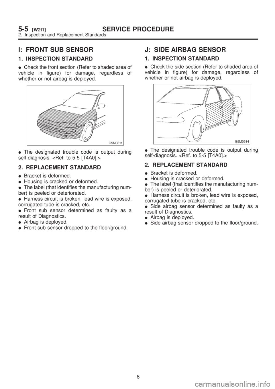
I: FRONT SUB SENSOR
1. INSPECTION STANDARD
ICheck the front section (Refer to shaded area of
vehicle in figure) for damage, regardless of
whether or not airbag is deployed.
G5M0311
IThe designated trouble code is output during
self-diagnosis.
2. REPLACEMENT STANDARD
IBracket is deformed.
IHousing is cracked or deformed.
IThe label (that identifies the manufacturing num-
ber) is peeled or deteriorated.
IHarness circuit is broken, lead wire is exposed,
corrugated tube is cracked, etc.
IFront sub sensor determined as faulty as a
result of Diagnostics.
IAirbag is deployed.
IFront sub sensor dropped to the floor/ground.
J: SIDE AIRBAG SENSOR
1. INSPECTION STANDARD
ICheck the side section (Refer to shaded area of
vehicle in figure) for damage, regardless of
whether or not airbag is deployed.
B5M0514
IThe designated trouble code is output during
self-diagnosis.
2. REPLACEMENT STANDARD
IBracket is deformed.
IHousing is cracked or deformed.
IThe label (that identifies the manufacturing num-
ber) is peeled or deteriorated.
IHarness circuit is broken, lead wire is exposed,
corrugated tube is cracked, etc.
ISide airbag sensor determined as faulty as a
result of Diagnostics.
IAirbag is deployed.
ISide airbag sensor dropped to the floor/ground.
8
5-5[W2I1]SERVICE PROCEDURE
2. Inspection and Replacement Standards